EP2460976A2 - Confinement de rotor de turbine à gaz - Google Patents
Confinement de rotor de turbine à gaz Download PDFInfo
- Publication number
- EP2460976A2 EP2460976A2 EP11191950A EP11191950A EP2460976A2 EP 2460976 A2 EP2460976 A2 EP 2460976A2 EP 11191950 A EP11191950 A EP 11191950A EP 11191950 A EP11191950 A EP 11191950A EP 2460976 A2 EP2460976 A2 EP 2460976A2
- Authority
- EP
- European Patent Office
- Prior art keywords
- shaft
- high pressure
- tie
- compressor rotor
- rotor
- Prior art date
- Legal status (The legal status is an assumption and is not a legal conclusion. Google has not performed a legal analysis and makes no representation as to the accuracy of the status listed.)
- Withdrawn
Links
Images

Classifications
-
- F—MECHANICAL ENGINEERING; LIGHTING; HEATING; WEAPONS; BLASTING
- F01—MACHINES OR ENGINES IN GENERAL; ENGINE PLANTS IN GENERAL; STEAM ENGINES
- F01D—NON-POSITIVE DISPLACEMENT MACHINES OR ENGINES, e.g. STEAM TURBINES
- F01D21/00—Shutting-down of machines or engines, e.g. in emergency; Regulating, controlling, or safety means not otherwise provided for
- F01D21/04—Shutting-down of machines or engines, e.g. in emergency; Regulating, controlling, or safety means not otherwise provided for responsive to undesired position of rotor relative to stator or to breaking-off of a part of the rotor, e.g. indicating such position
- F01D21/045—Shutting-down of machines or engines, e.g. in emergency; Regulating, controlling, or safety means not otherwise provided for responsive to undesired position of rotor relative to stator or to breaking-off of a part of the rotor, e.g. indicating such position special arrangements in stators or in rotors dealing with breaking-off of part of rotor
-
- F—MECHANICAL ENGINEERING; LIGHTING; HEATING; WEAPONS; BLASTING
- F01—MACHINES OR ENGINES IN GENERAL; ENGINE PLANTS IN GENERAL; STEAM ENGINES
- F01D—NON-POSITIVE DISPLACEMENT MACHINES OR ENGINES, e.g. STEAM TURBINES
- F01D5/00—Blades; Blade-carrying members; Heating, heat-insulating, cooling or antivibration means on the blades or the members
- F01D5/02—Blade-carrying members, e.g. rotors
-
- F—MECHANICAL ENGINEERING; LIGHTING; HEATING; WEAPONS; BLASTING
- F01—MACHINES OR ENGINES IN GENERAL; ENGINE PLANTS IN GENERAL; STEAM ENGINES
- F01D—NON-POSITIVE DISPLACEMENT MACHINES OR ENGINES, e.g. STEAM TURBINES
- F01D5/00—Blades; Blade-carrying members; Heating, heat-insulating, cooling or antivibration means on the blades or the members
- F01D5/02—Blade-carrying members, e.g. rotors
- F01D5/026—Shaft to shaft connections
-
- F—MECHANICAL ENGINEERING; LIGHTING; HEATING; WEAPONS; BLASTING
- F01—MACHINES OR ENGINES IN GENERAL; ENGINE PLANTS IN GENERAL; STEAM ENGINES
- F01D—NON-POSITIVE DISPLACEMENT MACHINES OR ENGINES, e.g. STEAM TURBINES
- F01D5/00—Blades; Blade-carrying members; Heating, heat-insulating, cooling or antivibration means on the blades or the members
- F01D5/02—Blade-carrying members, e.g. rotors
- F01D5/06—Rotors for more than one axial stage, e.g. of drum or multiple disc type; Details thereof, e.g. shafts, shaft connections
-
- F—MECHANICAL ENGINEERING; LIGHTING; HEATING; WEAPONS; BLASTING
- F01—MACHINES OR ENGINES IN GENERAL; ENGINE PLANTS IN GENERAL; STEAM ENGINES
- F01D—NON-POSITIVE DISPLACEMENT MACHINES OR ENGINES, e.g. STEAM TURBINES
- F01D5/00—Blades; Blade-carrying members; Heating, heat-insulating, cooling or antivibration means on the blades or the members
- F01D5/02—Blade-carrying members, e.g. rotors
- F01D5/06—Rotors for more than one axial stage, e.g. of drum or multiple disc type; Details thereof, e.g. shafts, shaft connections
- F01D5/066—Connecting means for joining rotor-discs or rotor-elements together, e.g. by a central bolt, by clamps
-
- F—MECHANICAL ENGINEERING; LIGHTING; HEATING; WEAPONS; BLASTING
- F05—INDEXING SCHEMES RELATING TO ENGINES OR PUMPS IN VARIOUS SUBCLASSES OF CLASSES F01-F04
- F05D—INDEXING SCHEME FOR ASPECTS RELATING TO NON-POSITIVE-DISPLACEMENT MACHINES OR ENGINES, GAS-TURBINES OR JET-PROPULSION PLANTS
- F05D2260/00—Function
- F05D2260/30—Retaining components in desired mutual position
- F05D2260/31—Retaining bolts or nuts
Definitions
- the present application relates generally to gas turbine engines and more particularly to rotor containment for multi-shaft gas turbine engines.
- a gas turbine engine is designed to safely shut down following the ingestion of a foreign object or blade loss event. Efficient design practice results in close inter-shaft clearances in concentric multi-shaft designs. The disturbance from these events on the rotor stability can lead to shaft-to-shaft rubbing at speeds and forces sufficient to result in separation of one or more affected shafts.
- the engine must be designed to contain the structure during subsequent deceleration of the rotors. The use of a full length tie-shaft to join the compressor and turbine rotor sections further complicates the containment design. Furthermore, if a shaft separation event occurs, separating loads such as gas pressure will tend to split the compressor and turbine rotor sections (i.e. release of compressor pressure tends to force the turbine rotor aft), further complicating containment by providing two rotating masses to contain.
- a gas turbine engine comprising at least one spool assembly including at least a compressor rotor and a turbine rotor connected by a first shaft, the first shaft having a forward end connected to the compressor rotor and an aft end connected to the turbine rotor, the first shaft extending concentrically around a second shaft, the second shaft having a region of enlarged diameter located axially aft of the compressor rotor but axially forward of the forward end of the first shaft; the region of enlarged diameter having a diameter greater than an inner diameter of at least a portion of the forward end of the first shaft to cause the region of enlarged diameter of the second shaft to axially engage the first shaft in interference in the event that the second shaft is moved axially aft relative to the first shaft more than a pre-selected axial distance.
- a gas turbine engine comprising a low pressure spool assembly including at least a fan and a low pressure turbine connected by a low pressure shaft, a high pressure spool assembly including at least a high pressure compressor rotor and a high pressure turbine rotor connected by a high pressure shaft and a tie shaft, the high pressure shaft extending concentrically around the tie shaft, the tie-shaft having a region of enlarged diameter located axially aft of the high pressure compressor rotor but axially forward of a front end of the high pressure shaft, the region of enlarged diameter configured to cause the region to engage the high pressure shaft in an interference fit in the event that the region is moved axially aft relative to the high pressure shaft more than a pre-selected axial distance.
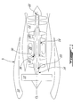
- Fig. 1 schematically depicts a turbofan engine A which, as an example, illustrates the application of the described subject matter.
- the turbofan engine A includes a nacelle 10, a low pressure spool assembly which includes at least a fan 12 and a low pressure turbine 14 connected by a low pressure shaft 16, and a high pressure spool which includes a high pressure compressor 18 and a high pressure turbine 20 connected by a tie-shaft 22 and a high pressure shaft 24.
- the engine further comprises a combustor 26.
- the upstream end of the high pressure shaft 24 terminates in a bell shaped support 30.
- the support 30 has a collar 35 having an internal diameter 35a that has a close radial tolerance with the tie-shaft 22.
- Threads 38 may be provided on the outside diameter of the tie shaft 22 for engagement with a threaded coupling 34 axially downstream of collar 35 of the high pressure shaft 24.
- the tie-shaft 22 includes a catcher 36, which may be provided as an integral portion of the tie-shaft 22, with an increased outer diameter portion that is at least greater than an inside diameter 35a of the collar 35, depending from the high pressure shaft 24, through which the tie-shaft 22 extends.
- the catcher 36 is located downstream of the high pressure compressor 18, but axially upstream of where the tie-shaft 22 enters the high pressure shaft 24, with close axial tolerances. Since the catcher 36 is radially larger than the inner diameter 35a of collar 35 of the high pressure shaft 24, the catcher portion 36 is too large to slide axially through the high pressure shaft 24. Axial movement of the catcher 36, aft relative to the high pressure shaft 24 will cause interference between the catcher 36 and the high pressure shaft collar 35, effectively restraining the tie-shaft 22 from moving downstream relative to high pressure shaft 24 which can be seen as joining the tie shaft 22 with the high pressure shaft 24.
- the presence of the bell shaped support 30 on the high pressure shaft 24 tends to have a centering effect on the high pressure compressor rotor 18.
- the centralizing function provides a conical contact zone on the rotor 18, which provides axial and radial restraint. This reduces reliance on features such as seals and aerofoils to centralize the rotor if the mid rotor radial connection is lost and promotes energy dissipation between the set of more structurally capable rotating and static components.
Landscapes
- Engineering & Computer Science (AREA)
- Mechanical Engineering (AREA)
- General Engineering & Computer Science (AREA)
- Structures Of Non-Positive Displacement Pumps (AREA)
- Turbine Rotor Nozzle Sealing (AREA)
Applications Claiming Priority (1)
| Application Number | Priority Date | Filing Date | Title |
|---|---|---|---|
| US41959610P | 2010-12-03 | 2010-12-03 |
Publications (2)
| Publication Number | Publication Date |
|---|---|
| EP2460976A2 true EP2460976A2 (fr) | 2012-06-06 |
| EP2460976A3 EP2460976A3 (fr) | 2017-03-08 |
Family
ID=45218378
Family Applications (1)
| Application Number | Title | Priority Date | Filing Date |
|---|---|---|---|
| EP11191950.2A Withdrawn EP2460976A3 (fr) | 2010-12-03 | 2011-12-05 | Confinement de rotor de turbine à gaz |
Country Status (3)
| Country | Link |
|---|---|
| US (1) | US9291070B2 (fr) |
| EP (1) | EP2460976A3 (fr) |
| CA (1) | CA2760454C (fr) |
Families Citing this family (8)
| Publication number | Priority date | Publication date | Assignee | Title |
|---|---|---|---|---|
| CA2760454C (fr) | 2010-12-03 | 2019-02-19 | Pratt & Whitney Canada Corp. | Element de confinement de rotor turbine a gaz |
| US9291057B2 (en) * | 2012-07-18 | 2016-03-22 | United Technologies Corporation | Tie shaft for gas turbine engine and flow forming method for manufacturing same |
| WO2014058463A1 (fr) * | 2012-10-09 | 2014-04-17 | United Technologies Corporation | Turboréacteur doté d'une fonction de déviation inter-arbres |
| US10550718B2 (en) | 2017-03-31 | 2020-02-04 | The Boeing Company | Gas turbine engine fan blade containment systems |
| US10487684B2 (en) | 2017-03-31 | 2019-11-26 | The Boeing Company | Gas turbine engine fan blade containment systems |
| CN208310846U (zh) * | 2018-04-26 | 2019-01-01 | 贵州智慧能源科技有限公司 | 一种具有支撑定心及增压的轴及燃气轮机转子 |
| US10934844B2 (en) | 2018-05-31 | 2021-03-02 | Rolls-Royce Corporation | Gas turbine engine with fail-safe shaft scheme |
| US11203934B2 (en) * | 2019-07-30 | 2021-12-21 | General Electric Company | Gas turbine engine with separable shaft and seal assembly |
Citations (1)
| Publication number | Priority date | Publication date | Assignee | Title |
|---|---|---|---|---|
| EP2365185A2 (fr) * | 2010-03-10 | 2011-09-14 | United Technologies Corporation | Assemblage du section compresseur et turbine d'un moteur de turbine à gaz doté d'un système d'accouplement par adhérence de l'arbre de compresseur haute pression |
Family Cites Families (56)
| Publication number | Priority date | Publication date | Assignee | Title |
|---|---|---|---|---|
| GB182700A (en) | 1921-07-22 | 1922-07-13 | Sydney Asline Ward | Improvements in or relating to windmills |
| US2679907A (en) | 1950-05-18 | 1954-06-01 | United Aircraft Corp | Dual rotation coaxial propeller mechanism |
| US2866522A (en) | 1954-08-06 | 1958-12-30 | Rolls Royce | Lubricating arrangements for bearings of rotatable shafts |
| GB837309A (en) | 1956-11-08 | 1960-06-09 | Rolls Royce | Improvements in or relating to gas-turbine engines |
| GB903945A (en) | 1957-10-29 | 1962-08-22 | Rolls Royce | Improvements in or relating to gas-turbine engines |
| US2999000A (en) | 1960-04-14 | 1961-09-05 | Spat Melvin | Lubricating arrangement for co-axial shafts |
| CH418363A (de) | 1964-06-26 | 1966-08-15 | Escher Wyss Ag | Wellendichtung für eine thermische Maschine |
| GB1085619A (en) | 1966-03-09 | 1967-10-04 | Rolls Royce | Gas turbine engine |
| US3680803A (en) | 1970-08-04 | 1972-08-01 | Artisan Ind | Turbine drive for photographic film processing machines |
| GB1421540A (en) | 1972-11-24 | 1976-01-21 | Rolls Royce | Shaft bearing assemblies |
| FR2317501A1 (fr) | 1975-07-09 | 1977-02-04 | Snecma | Dispositif d'accouplement pour moteur a turbine a gaz |
| US4039848A (en) | 1975-11-10 | 1977-08-02 | Winderl William R | Wind operated generator |
| US4086012A (en) | 1976-09-20 | 1978-04-25 | The United States Of America As Represented By The Secretary Of The Navy | Rotational energy absorbing coupling |
| US4283096A (en) | 1978-04-21 | 1981-08-11 | United Technologies Corporation | Intershaft bearing |
| GB2043833B (en) | 1979-03-17 | 1982-11-10 | Rolls Royce | Rotor assembly |
| US4211424A (en) | 1979-04-16 | 1980-07-08 | Stein Philip C | Centrifugally compensated seal for sealing between concentric shafts |
| FR2515734A1 (fr) | 1981-11-05 | 1983-05-06 | Snecma | Systeme d'ajustement du centrage d'une roue de turbomachine et turbomachine munie de moyens permettant l'application dudit systeme |
| EP0162340A1 (fr) | 1984-05-15 | 1985-11-27 | A. S. Kongsberg Väpenfabrikk | Dispositif de réglage de la composante axiale du jeu de travail pour une turbine radiale à gaz |
| GB2165018B (en) | 1984-08-02 | 1988-12-29 | Lonrho Plc | Poppet valve arrangements |
| GB8730187D0 (en) | 1987-12-24 | 1988-02-03 | Rolls Royce Plc | Overspeed limiter for gas turbine aeroengine |
| US4972986A (en) | 1988-11-01 | 1990-11-27 | Eg&G Sealol, Inc. | Circumferential inter-seal for sealing between relatively rotatable concentric shafts |
| US5054996A (en) | 1990-07-27 | 1991-10-08 | General Electric Company | Thermal linear actuator for rotor air flow control in a gas turbine |
| SE470218B (sv) | 1992-04-01 | 1993-12-06 | Abb Carbon Ab | Förfarande och anordning för reglering av skoveltoppspel hos en roterande maskin |
| US5407386A (en) | 1993-02-04 | 1995-04-18 | United Technologies Corporation | Fail safe drive shaft system |
| US5433584A (en) | 1994-05-05 | 1995-07-18 | Pratt & Whitney Canada, Inc. | Bearing support housing |
| US5537814A (en) * | 1994-09-28 | 1996-07-23 | General Electric Company | High pressure gas generator rotor tie rod system for gas turbine engine |
| GB2322165B (en) | 1997-02-15 | 2001-02-28 | Rolls Royce Plc | Ducted fan gas turbine engine |
| GB2326679B (en) | 1997-06-25 | 2000-07-26 | Rolls Royce Plc | Ducted fan gas turbine engine |
| GB9822638D0 (en) | 1998-10-16 | 1998-12-09 | Rolls Royce Plc | Nested rotary shafts and support therefor |
| US6240719B1 (en) | 1998-12-09 | 2001-06-05 | General Electric Company | Fan decoupler system for a gas turbine engine |
| US6491497B1 (en) | 2000-09-22 | 2002-12-10 | General Electric Company | Method and apparatus for supporting rotor assemblies during unbalances |
| US6619908B2 (en) | 2001-09-10 | 2003-09-16 | Pratt & Whitney Canada Corp. | Axial and radial seal arrangement |
| GB0127087D0 (en) | 2001-11-10 | 2002-01-02 | Rolls Royce Plc | Shaft bearings |
| GB2383380B (en) | 2001-12-19 | 2005-05-25 | Rolls Royce Plc | Rotor assemblies for gas turbine engines |
| GB0221070D0 (en) | 2002-09-11 | 2002-10-23 | Davison Ernest | Flexispline motor |
| GB0308467D0 (en) | 2003-04-11 | 2003-05-21 | Rolls Royce Plc | Method and system for analysing tachometer and vibration data from an apparatus having one or more rotary components |
| GB2401651B (en) | 2003-05-14 | 2006-03-01 | Rolls Royce Plc | A gas turbine engine |
| GB0311737D0 (en) | 2003-05-22 | 2003-06-25 | Rolls Royce Plc | A stub axle |
| GB0317055D0 (en) | 2003-07-22 | 2003-08-27 | Cross Mfg Co 1938 Ltd | Improvements relating to aspirating face seals and thrust bearings |
| FR2866068B1 (fr) | 2004-02-06 | 2006-07-07 | Snecma Moteurs | Turboreacteur a soufflante solidaire d'un arbre d'entrainement supporte par un premier et un deuxieme paliers |
| US7294947B2 (en) | 2004-03-01 | 2007-11-13 | Flux Drive, Inc. | Apparatus for transferring torque magnetically |
| FR2877398B1 (fr) | 2004-10-28 | 2009-10-30 | Snecma Moteurs Sa | Moteur rotatif avec un palier d'arbre a deux raideurs |
| FR2878289A1 (fr) | 2004-11-19 | 2006-05-26 | Snecma Moteurs Sa | Turbomachine avec un dispositif de decouplage commun aux premier et deuxieme paliers de son arbre d'entrainement |
| US7435052B2 (en) | 2005-05-20 | 2008-10-14 | Honeywell International Inc. | Shaft oil purge system |
| DE102005052819A1 (de) * | 2005-11-05 | 2007-05-10 | Mtu Aero Engines Gmbh | Turbomaschine, insbesondere Gasturbine |
| US7874136B2 (en) | 2006-04-27 | 2011-01-25 | Pratt & Whitney Canada Corp. | Rotor containment element with frangible connections |
| US8262353B2 (en) | 2007-11-30 | 2012-09-11 | General Electric Company | Decoupler system for rotor assemblies |
| US8287242B2 (en) * | 2008-11-17 | 2012-10-16 | United Technologies Corporation | Turbine engine rotor hub |
| DE102008060571A1 (de) * | 2008-12-04 | 2010-06-10 | Mtu Aero Engines Gmbh | Montagevorrichtung für ein Rotorsystem einer Axial-Strömungsmaschine |
| US8162615B2 (en) * | 2009-03-17 | 2012-04-24 | United Technologies Corporation | Split disk assembly for a gas turbine engine |
| GB2474299B (en) | 2009-10-12 | 2012-02-08 | Rolls Royce Plc | Fan retention shaft |
| US8650885B2 (en) | 2009-12-22 | 2014-02-18 | United Technologies Corporation | Retaining member for use with gas turbine engine shaft and method of assembly |
| US20110219781A1 (en) * | 2010-03-10 | 2011-09-15 | Daniel Benjamin | Gas turbine engine with tie shaft for axial high pressure compressor rotor |
| EP2616698B1 (fr) | 2010-09-16 | 2019-04-10 | Stein Seal Company | Système d'étanchéité intercalaire servant à réduire au minimum la torsion induite par pression |
| US8794923B2 (en) * | 2010-10-29 | 2014-08-05 | United Technologies Corporation | Gas turbine engine rotor tie shaft arrangement |
| CA2760454C (fr) | 2010-12-03 | 2019-02-19 | Pratt & Whitney Canada Corp. | Element de confinement de rotor turbine a gaz |
-
2011
- 2011-12-02 CA CA2760454A patent/CA2760454C/fr active Active
- 2011-12-02 US US13/309,709 patent/US9291070B2/en active Active
- 2011-12-05 EP EP11191950.2A patent/EP2460976A3/fr not_active Withdrawn
Patent Citations (1)
| Publication number | Priority date | Publication date | Assignee | Title |
|---|---|---|---|---|
| EP2365185A2 (fr) * | 2010-03-10 | 2011-09-14 | United Technologies Corporation | Assemblage du section compresseur et turbine d'un moteur de turbine à gaz doté d'un système d'accouplement par adhérence de l'arbre de compresseur haute pression |
Also Published As
| Publication number | Publication date |
|---|---|
| CA2760454C (fr) | 2019-02-19 |
| EP2460976A3 (fr) | 2017-03-08 |
| CA2760454A1 (fr) | 2012-06-03 |
| US9291070B2 (en) | 2016-03-22 |
| US20120141294A1 (en) | 2012-06-07 |
Similar Documents
| Publication | Publication Date | Title |
|---|---|---|
| US9291070B2 (en) | Gas turbine rotor containment | |
| CA2713316C (fr) | Architecture de section de turbine a gaz | |
| US10815825B2 (en) | Post FBO windmilling bumper | |
| EP3205840B1 (fr) | Système de support de rotor en comprenant composants en alliage à mémoire de forme pour une turbine à gaz | |
| CA2861291C (fr) | Support de roulemement frangible double | |
| JP5788519B2 (ja) | コンプレッサホイールの破裂の際にシャフトを軸方向に固定するための手段を有する排気ガスターボチャージャ | |
| RU2681392C2 (ru) | Турбомашина, содержащая средство для отсоединения вентилятора | |
| US8376700B2 (en) | Compressed air starter for turbomachine | |
| JP6184036B2 (ja) | 耐摩擦性ファンケース | |
| US10557374B2 (en) | Gas turbine and method for protecting a gas turbine in case of a shaft break | |
| US20180080504A1 (en) | Gas turbine engine with a geared turbofan arrangement | |
| EP3287624A1 (fr) | Boîtier de vitesses avec un support affaibli integré | |
| EP2906807B1 (fr) | Turboréacteur avec élément de déviation inter-arbres | |
| US9938988B2 (en) | Exhaust gas turbocharger | |
| US11643944B2 (en) | Turbine shaft of a turbomachine and method for protecting against overspeed of said shaft | |
| EP2395203A2 (fr) | Système de confinement léger de compresseur à diffuseur sans ailette | |
| EP2935785B1 (fr) | Entretoise de pied pour agencement entre un disque de rotor et un pied d'une aube de rotor | |
| JP2012233474A (ja) | タービンエンジン及びその荷重低減装置 | |
| WO2014100553A1 (fr) | Disque de turbine doté d'une concentration de contraintes de col réduite | |
| EP3663538A1 (fr) | Ensemble de protection contre la survitesse d'un rotor | |
| EP4592501A1 (fr) | Système de confinement de turbine | |
| CA3262499A1 (fr) | Système de confinement de roue |
Legal Events
| Date | Code | Title | Description |
|---|---|---|---|
| PUAI | Public reference made under article 153(3) epc to a published international application that has entered the european phase |
Free format text: ORIGINAL CODE: 0009012 |
|
| AK | Designated contracting states |
Kind code of ref document: A2 Designated state(s): AL AT BE BG CH CY CZ DE DK EE ES FI FR GB GR HR HU IE IS IT LI LT LU LV MC MK MT NL NO PL PT RO RS SE SI SK SM TR |
|
| AX | Request for extension of the european patent |
Extension state: BA ME |
|
| PUAL | Search report despatched |
Free format text: ORIGINAL CODE: 0009013 |
|
| AK | Designated contracting states |
Kind code of ref document: A3 Designated state(s): AL AT BE BG CH CY CZ DE DK EE ES FI FR GB GR HR HU IE IS IT LI LT LU LV MC MK MT NL NO PL PT RO RS SE SI SK SM TR |
|
| AX | Request for extension of the european patent |
Extension state: BA ME |
|
| RIC1 | Information provided on ipc code assigned before grant |
Ipc: F01D 21/04 20060101ALI20170130BHEP Ipc: F01D 5/02 20060101AFI20170130BHEP Ipc: F01D 5/06 20060101ALI20170130BHEP |
|
| STAA | Information on the status of an ep patent application or granted ep patent |
Free format text: STATUS: REQUEST FOR EXAMINATION WAS MADE |
|
| 17P | Request for examination filed |
Effective date: 20170908 |
|
| RBV | Designated contracting states (corrected) |
Designated state(s): AL AT BE BG CH CY CZ DE DK EE ES FI FR GB GR HR HU IE IS IT LI LT LU LV MC MK MT NL NO PL PT RO RS SE SI SK SM TR |
|
| STAA | Information on the status of an ep patent application or granted ep patent |
Free format text: STATUS: EXAMINATION IS IN PROGRESS |
|
| 17Q | First examination report despatched |
Effective date: 20190612 |
|
| STAA | Information on the status of an ep patent application or granted ep patent |
Free format text: STATUS: THE APPLICATION IS DEEMED TO BE WITHDRAWN |
|
| 18D | Application deemed to be withdrawn |
Effective date: 20200103 |