EP2461076A1 - Soupape latérale - Google Patents
Soupape latérale Download PDFInfo
- Publication number
- EP2461076A1 EP2461076A1 EP10015229A EP10015229A EP2461076A1 EP 2461076 A1 EP2461076 A1 EP 2461076A1 EP 10015229 A EP10015229 A EP 10015229A EP 10015229 A EP10015229 A EP 10015229A EP 2461076 A1 EP2461076 A1 EP 2461076A1
- Authority
- EP
- European Patent Office
- Prior art keywords
- connecting piece
- outer sleeve
- inner sleeve
- sleeve
- fixing portion
- Prior art date
- Legal status (The legal status is an assumption and is not a legal conclusion. Google has not performed a legal analysis and makes no representation as to the accuracy of the status listed.)
- Granted
Links
Images



Classifications
-
- F—MECHANICAL ENGINEERING; LIGHTING; HEATING; WEAPONS; BLASTING
- F16—ENGINEERING ELEMENTS AND UNITS; GENERAL MEASURES FOR PRODUCING AND MAINTAINING EFFECTIVE FUNCTIONING OF MACHINES OR INSTALLATIONS; THERMAL INSULATION IN GENERAL
- F16K—VALVES; TAPS; COCKS; ACTUATING-FLOATS; DEVICES FOR VENTING OR AERATING
- F16K27/00—Construction of housing; Use of materials therefor
- F16K27/04—Construction of housing; Use of materials therefor of sliding valves
- F16K27/044—Construction of housing; Use of materials therefor of sliding valves slide valves with flat obturating members
- F16K27/045—Construction of housing; Use of materials therefor of sliding valves slide valves with flat obturating members with pivotal obturating members
Definitions
- the invention relates to a side valve according to the preamble of patent claim 1.
- Known side valves control the discharge of media from fittings while simultaneously redirecting the flow direction.
- Known side valves comprise an outer sleeve in which a connection piece is attached laterally, and an inner sleeve, which is attached longitudinally to the outer sleeve, so that a gap is formed between inner sleeve and outer sleeve.
- On the inner sleeve is a valve upper part sealingly, via which the inflow amount is controllable.
- the inner sleeve and the connecting piece are screwed with the outer sleeve using a sealing adhesive, wherein the sealing adhesive is applied to the threaded portion before the screwing.
- connection piece which has a relatively small outer diameter, only a small connection surface with the outer sleeve, which is why the connection between the connection piece and outer sleeve is only partially reliable.
- the connecting piece which has a relatively small outer diameter, only a small connection surface with the outer sleeve, which is why the connection between the connection piece and outer sleeve is only partially reliable.
- the invention aims to remedy this situation.
- the invention has for its object to provide a side valve of the aforementioned type, in which the connecting piece is reliably connected to the side valve. According to the invention, this object is solved by the features of the characterizing part of patent claim 1.
- a side valve in which the connecting piece is reliably connected to the side valve.
- a separate Connecting piece are connected to each other via the outer sleeve and inner sleeve, and on which the connecting piece is formed, a one-piece Anformung the connection piece is made possible.
- all parts can be produced as a turned part, which allows a cost-effective production of the side valve made of different materials.
- the connecting piece has a first, inner sleeve-side fastening section for fastening the inner sleeve and a second, outer sleeve-side fastening section for fastening the outer sleeve, wherein the outer sleeve has a fastening section which corresponds to the outer sleeve-side fastening section of the connecting piece.
- the outer sleeve-side and the inner sleeve-side fastening section are preferably in the form of an internal thread, and the fastening section of the outer sleeve and the fastening section of the inner sleeve are formed as an external thread.
- the outer sleeve-side fixing portion and the inner sleeve-side fixing portion of the connecting piece define an intermediate surface into which a hole introduced into the connecting piece projects, which is arranged inside the lateral connecting piece.
- the inner sleeve-side fastening section and / or the outer sleeve-side fastening section of the connecting piece open into a shoulder against which a seal is applied.
- the seal between the inner sleeve and / or outer sleeve and the connecting piece is increased.
- the inner sleeve has a circumferential collar at its end opposite the connecting thread. hereby is achieved a contact surface for a sealing element of a screwed into the outer sleeve valve shell.
- the connector is formed as a one-piece rotary member. This allows a cost-effective production of the connector made of different materials.
- preferably designed as an external thread mounting portion of the outer sleeve is bounded by a shoulder which forms a stop which bears against a flat, preferably designed as an internal thread outer sleeve-side mounting portion of the connecting piece surface.
- a stop may also be formed by the end face of the outer sleeve, which bears against a stop surface within the connecting piece.
- a shoulder which forms a stop which bears against a flat, preferably designed as an internal thread inner sleeve side mounting portion of the connecting surface, this is a good seal between the inner sleeve and Connector achievable.
- the stop may also be arranged such that it bears against a stop surface within the connecting piece.
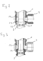
- the side valve chosen as an embodiment consists essentially of an outer sleeve 1 and an inner sleeve 3, which are connected to one another via a connecting piece 2, and a valve head 4,
- the outer sleeve 1 is made in the embodiment of brass and formed substantially hollow cylindrical. Over about 5/4 of the length of the outer sleeve an external thread 11 is introduced into this. Spaced to the external thread 11, a diameter-reduced second external thread 12 is further introduced into the outer sleeve 1, wherein between the second external thread 12 and the first external thread 11, a shoulder 13 is formed, through which a stop 14 is formed.
- the second external thread 12 terminates in a chamfer 15, through which a simplified screwing into the connecting piece 2 is made possible.
- the chamfer 15 forms a sealing surface which sealingly bears against the sealing ring 29 applied to the stop 28 of the connecting piece 2.
- an internal thread 16 for fastening a valve upper part 4 is further introduced on the inner side of the outer sleeve 1.
- the inner diameter of the outer sleeve 1 is executed by two spaced apart in the inner wall of the outer sleeve paragraphs 17 in the direction of the chamfer 15 gradually reduced executed.
- the connecting piece 2 is made in the embodiment of brass and consists essentially of a sleeve 21, to which a connecting piece 22 is integrally formed.
- a connecting piece 22 is integrally formed in the ball-neck-like design sleeve 21
- three flat surfaces 211 are formed circumferentially for better handling of the connector 2.
- two internal threads 23, 24 are introduced at the end, between which an intermediate surface 25 is arranged.
- the first internal thread 23 reduced in diameter relative to the second internal thread 24 serves to fasten the inner sleeve 3
- the second internal thread 24 serves to fasten the outer sleeve 1 via the second external thread 12 corresponding thereto.
- the intermediate surface 25 is the first internal thread through a shoulder 27 and the second internal thread is bounded by a shoulder 28.
- the shoulders 27, 28 serve to abut a circumferential sealing ring 29.
- the first internal thread 23 is circumferentially surrounded by a flat surface 231 and the second internal thread at the end by a plane surface 241.
- the Planf kauen 231, 241 serve the investment of outer sleeve 1 and inner sleeve. 3
- the molded onto the sleeve 21 connecting piece 22 is formed substantially hollow cylindrical, wherein in its outer circumferential surface a connecting thread 221 is formed. Within the connecting piece 22 is enclosed by this bore 26 introduced into the sleeve 21, which through the intermediate surface 25 passes.
- the connecting piece 22 is formed in the embodiment as a brass rotating part.
- the inner sleeve 3 is also executed in the embodiment as a largely hollow cylindrical brass turned part.
- a connection thread 31 is introduced at one end in the inner sleeve 3 .
- another connection piece for example a bayonet closure.
- a reduced diameter screw-in thread 32 Spaced to the connecting thread 31, a reduced diameter screw-in thread 32 is furthermore arranged.
- the screw-in thread 32 is bounded on its side facing the connecting thread 31 by a shoulder 33 which forms a stop 331. Between the shoulder 33 and the connecting thread 31, a groove 34 is arranged.
- a circumferential collar 36 is integrally formed on the inner sleeve 3.
- an inner hexagon 38 for handling the inner sleeve 3 is further formed in the inner sleeve 3 in its inner wall.
- the valve upper part 4 used in the exemplary embodiment has a head piece 41, which is penetrated centrally by a spindle 42 guided radially in this case. About the spindle 42, a valve is actuated, which comes to rest on the collar 36 of the inner sleeve 3.
- the valve is formed in the embodiment of a control disk 43 and a passage disc 44.
- the control disk 43 is positively connected to the spindle 42.
- the passage plate 44 is provided in the head piece 41, to which a sealing element 45 connects, which comes on the collar 36 of the inner sleeve 3 to the plant.
- the head piece 41 consists essentially of a symmetrical hollow body whose two end faces are open. On its inner sleeve 3 facing Side, the head piece 41 a sleeve-like part 410. Passage windows 411 are provided in the part 410. Following the passage windows 411, the head piece 41 can be screwed externally with a thread 412 into the internal thread 16 of the outer sleeve 1. After screwing the sealing element 45 rests on the collar 36 of the inner sleeve 3.
- Such valve tops are the expert, for example from the DE 3207895 C2 known.
- a smooth or rough insertion surface is arranged instead of the internal thread 23, 24 of the connecting piece 2.
- the connection between outer sleeve or inner sleeve, which have a corresponding thereto smooth or rough mounting portion, and connecting piece via an adhesive is also a connection via a welded or soldered connection conceivable, in which case the attachment portions need only have minimal dimensions. Even an attachment of outer and inner sleeve and connector on impact is conceivable.
- valve upper part 4 is screwed with the connecting thread 412 in the inner thread 16 of the outer sleeve 1, so that the sealing element 45 on the collar 36 of the inner sleeve 3 sealingly rests.
- the passage windows 411 open into the intermediate space formed between outer sleeve 1 and inner sleeve 3.
- the medium In the assembled state of the side valve, the medium enters through the inner sleeve 3 in the side valve.
- the valve upper part 4 When the valve upper part 4 is open, the medium passes through the passage windows 411 and flows in the opposite direction through the intermediate space formed between the outer sleeve 1 and the inner sleeve 3, until it emerges through the bore 26 of the connecting piece 2 through the connecting piece 22.
Landscapes
- Engineering & Computer Science (AREA)
- General Engineering & Computer Science (AREA)
- Mechanical Engineering (AREA)
- Valve Housings (AREA)
Priority Applications (4)
| Application Number | Priority Date | Filing Date | Title |
|---|---|---|---|
| EP10015229.7A EP2461076B1 (fr) | 2010-12-02 | 2010-12-02 | Soupape latérale |
| TW100143859A TWI554704B (zh) | 2010-12-02 | 2011-11-30 | 側閥 |
| US13/309,023 US9033312B2 (en) | 2010-12-02 | 2011-12-01 | Side valve |
| CA2760168A CA2760168C (fr) | 2010-12-02 | 2011-12-01 | Soupape laterale |
Applications Claiming Priority (1)
| Application Number | Priority Date | Filing Date | Title |
|---|---|---|---|
| EP10015229.7A EP2461076B1 (fr) | 2010-12-02 | 2010-12-02 | Soupape latérale |
Publications (2)
| Publication Number | Publication Date |
|---|---|
| EP2461076A1 true EP2461076A1 (fr) | 2012-06-06 |
| EP2461076B1 EP2461076B1 (fr) | 2014-12-31 |
Family
ID=43877155
Family Applications (1)
| Application Number | Title | Priority Date | Filing Date |
|---|---|---|---|
| EP10015229.7A Active EP2461076B1 (fr) | 2010-12-02 | 2010-12-02 | Soupape latérale |
Country Status (4)
| Country | Link |
|---|---|
| US (1) | US9033312B2 (fr) |
| EP (1) | EP2461076B1 (fr) |
| CA (1) | CA2760168C (fr) |
| TW (1) | TWI554704B (fr) |
Citations (7)
| Publication number | Priority date | Publication date | Assignee | Title |
|---|---|---|---|---|
| DE3207895C2 (de) | 1982-03-05 | 1983-12-29 | Fa. Otto Flühs, 5880 Lüdenscheid | Ventiloberteil für Sanitärarmaturen |
| DE8703969U1 (de) * | 1987-03-17 | 1987-05-07 | Aloys F. Dornbracht Gmbh & Co, 5860 Iserlohn | Absperrventil als Bestandteil von Sanitärarmaturen |
| US5901735A (en) * | 1994-09-15 | 1999-05-11 | Silvano Breda | Diverter valves with integral back flow preventer and inlet and outlet check valve mechanisms |
| DE20219008U1 (de) * | 2002-12-06 | 2004-04-22 | Interforge Klee Gmbh | Wasserarmatur |
| US20060016487A1 (en) * | 2004-07-20 | 2006-01-26 | Ing Tzon Co., Ltd. | Control valve having pressure balance effect |
| DE102007033560A1 (de) * | 2007-07-19 | 2009-01-29 | Friedrich Gampper Kg Metallwarenfabrik | Ventilvorrichtung |
| EP2042791A1 (fr) * | 2007-09-26 | 2009-04-01 | Flühs Drehtechnik GmbH | Soupape latérale |
Family Cites Families (2)
| Publication number | Priority date | Publication date | Assignee | Title |
|---|---|---|---|---|
| US4004775A (en) * | 1973-10-31 | 1977-01-25 | Elk Manufacturing Company, Inc. | Plug valve |
| KR20040071690A (ko) * | 2001-12-06 | 2004-08-12 | 아사히 유키자이 고교 가부시키가이샤 | 매니폴드 밸브 |
-
2010
- 2010-12-02 EP EP10015229.7A patent/EP2461076B1/fr active Active
-
2011
- 2011-11-30 TW TW100143859A patent/TWI554704B/zh active
- 2011-12-01 CA CA2760168A patent/CA2760168C/fr active Active
- 2011-12-01 US US13/309,023 patent/US9033312B2/en active Active
Patent Citations (7)
| Publication number | Priority date | Publication date | Assignee | Title |
|---|---|---|---|---|
| DE3207895C2 (de) | 1982-03-05 | 1983-12-29 | Fa. Otto Flühs, 5880 Lüdenscheid | Ventiloberteil für Sanitärarmaturen |
| DE8703969U1 (de) * | 1987-03-17 | 1987-05-07 | Aloys F. Dornbracht Gmbh & Co, 5860 Iserlohn | Absperrventil als Bestandteil von Sanitärarmaturen |
| US5901735A (en) * | 1994-09-15 | 1999-05-11 | Silvano Breda | Diverter valves with integral back flow preventer and inlet and outlet check valve mechanisms |
| DE20219008U1 (de) * | 2002-12-06 | 2004-04-22 | Interforge Klee Gmbh | Wasserarmatur |
| US20060016487A1 (en) * | 2004-07-20 | 2006-01-26 | Ing Tzon Co., Ltd. | Control valve having pressure balance effect |
| DE102007033560A1 (de) * | 2007-07-19 | 2009-01-29 | Friedrich Gampper Kg Metallwarenfabrik | Ventilvorrichtung |
| EP2042791A1 (fr) * | 2007-09-26 | 2009-04-01 | Flühs Drehtechnik GmbH | Soupape latérale |
Also Published As
| Publication number | Publication date |
|---|---|
| CA2760168C (fr) | 2018-05-15 |
| US9033312B2 (en) | 2015-05-19 |
| TWI554704B (zh) | 2016-10-21 |
| CA2760168A1 (fr) | 2012-06-02 |
| TW201233930A (en) | 2012-08-16 |
| EP2461076B1 (fr) | 2014-12-31 |
| US20120138838A1 (en) | 2012-06-07 |
Similar Documents
| Publication | Publication Date | Title |
|---|---|---|
| DE102010001963B4 (de) | Vorrichtung zur Verminderung von Druckpulsen bei Drucksensoren | |
| DE102013111456B4 (de) | Abschaltventil | |
| DE19729392C2 (de) | Kraftstoffspeicher mit Abdichtung | |
| EP1696158A1 (fr) | Tête de robinet | |
| WO2024132484A1 (fr) | Pièce d'accouplement pour accouplement hydraulique | |
| DE102007009488A1 (de) | Dichtungsanordnung | |
| DE10023388A1 (de) | Hydraulisches Gerät | |
| EP2461076B1 (fr) | Soupape latérale | |
| EP3705739B1 (fr) | Capuchon de protection pour boulons filetés | |
| EP2042791B1 (fr) | Soupape latérale | |
| DE102010012207A1 (de) | Drosselschraube und hydraulisches Gerät | |
| DE102019107273B4 (de) | Verbindungsanordnung zwischen einer Steuereinrichtung und einem Anschlussflansch sowie Steuereinrichtung, Anschlussflansch und Befestigungselement für die Verbindungsanordnung | |
| DE10139169A1 (de) | Metallene Gewindebuchse und Schraubverbindung mittels einer Gewindebuchse | |
| EP2165101B1 (fr) | Dispositif de reglage | |
| DE8911001U1 (de) | Regelventil mit auswechselbarem Ventilsitzkörper | |
| EP1798485B1 (fr) | Distributeur de liquide | |
| DE112014006155B4 (de) | Ventil mit variablem Durchfluss und Verfahren zum Herstellen eines Ventils mit variablem Durchfluss | |
| DE4408929A1 (de) | Hydraulisches Ventil und Verfahren zu seiner Herstellung | |
| EP1880100B1 (fr) | Soupape d'injection de carburant pour moteurs a combustion interne | |
| DE8716061U1 (de) | Zweiwege-Stromregelventil für hydraulische Anlagen | |
| DE102004032203A1 (de) | Kraftstoffhochdruckspeicher | |
| EP3225827A1 (fr) | Soupape de gaz destiné à amener un carburant gazeux dans une tubulaire d'admission d'un moteur à combustion interne | |
| EP2841900A1 (fr) | Ensemble de capteurs servant à détecter au moins une propriété d'un milieu fluide et procédé de fabrication d'un tel ensemble de capteurs | |
| EP2706275B1 (fr) | Système de raccordement | |
| DE102008010135A1 (de) | Eckventil |
Legal Events
| Date | Code | Title | Description |
|---|---|---|---|
| PUAI | Public reference made under article 153(3) epc to a published international application that has entered the european phase |
Free format text: ORIGINAL CODE: 0009012 |
|
| AK | Designated contracting states |
Kind code of ref document: A1 Designated state(s): AL AT BE BG CH CY CZ DE DK EE ES FI FR GB GR HR HU IE IS IT LI LT LU LV MC MK MT NL NO PL PT RO RS SE SI SK SM TR |
|
| AX | Request for extension of the european patent |
Extension state: BA ME |
|
| 17P | Request for examination filed |
Effective date: 20121204 |
|
| GRAP | Despatch of communication of intention to grant a patent |
Free format text: ORIGINAL CODE: EPIDOSNIGR1 |
|
| INTG | Intention to grant announced |
Effective date: 20141007 |
|
| GRAS | Grant fee paid |
Free format text: ORIGINAL CODE: EPIDOSNIGR3 |
|
| GRAA | (expected) grant |
Free format text: ORIGINAL CODE: 0009210 |
|
| AK | Designated contracting states |
Kind code of ref document: B1 Designated state(s): AL AT BE BG CH CY CZ DE DK EE ES FI FR GB GR HR HU IE IS IT LI LT LU LV MC MK MT NL NO PL PT RO RS SE SI SK SM TR |
|
| REG | Reference to a national code |
Ref country code: CH Ref legal event code: EP Ref country code: GB Ref legal event code: FG4D Free format text: NOT ENGLISH |
|
| REG | Reference to a national code |
Ref country code: IE Ref legal event code: FG4D Free format text: LANGUAGE OF EP DOCUMENT: GERMAN |
|
| REG | Reference to a national code |
Ref country code: AT Ref legal event code: REF Ref document number: 704626 Country of ref document: AT Kind code of ref document: T Effective date: 20150215 |
|
| REG | Reference to a national code |
Ref country code: DE Ref legal event code: R096 Ref document number: 502010008595 Country of ref document: DE Effective date: 20150219 |
|
| PG25 | Lapsed in a contracting state [announced via postgrant information from national office to epo] |
Ref country code: NO Free format text: LAPSE BECAUSE OF FAILURE TO SUBMIT A TRANSLATION OF THE DESCRIPTION OR TO PAY THE FEE WITHIN THE PRESCRIBED TIME-LIMIT Effective date: 20150331 Ref country code: FI Free format text: LAPSE BECAUSE OF FAILURE TO SUBMIT A TRANSLATION OF THE DESCRIPTION OR TO PAY THE FEE WITHIN THE PRESCRIBED TIME-LIMIT Effective date: 20141231 Ref country code: LT Free format text: LAPSE BECAUSE OF FAILURE TO SUBMIT A TRANSLATION OF THE DESCRIPTION OR TO PAY THE FEE WITHIN THE PRESCRIBED TIME-LIMIT Effective date: 20141231 |
|
| REG | Reference to a national code |
Ref country code: NL Ref legal event code: VDEP Effective date: 20141231 |
|
| REG | Reference to a national code |
Ref country code: LT Ref legal event code: MG4D |
|
| PG25 | Lapsed in a contracting state [announced via postgrant information from national office to epo] |
Ref country code: LV Free format text: LAPSE BECAUSE OF FAILURE TO SUBMIT A TRANSLATION OF THE DESCRIPTION OR TO PAY THE FEE WITHIN THE PRESCRIBED TIME-LIMIT Effective date: 20141231 Ref country code: HR Free format text: LAPSE BECAUSE OF FAILURE TO SUBMIT A TRANSLATION OF THE DESCRIPTION OR TO PAY THE FEE WITHIN THE PRESCRIBED TIME-LIMIT Effective date: 20141231 Ref country code: SE Free format text: LAPSE BECAUSE OF FAILURE TO SUBMIT A TRANSLATION OF THE DESCRIPTION OR TO PAY THE FEE WITHIN THE PRESCRIBED TIME-LIMIT Effective date: 20141231 Ref country code: RS Free format text: LAPSE BECAUSE OF FAILURE TO SUBMIT A TRANSLATION OF THE DESCRIPTION OR TO PAY THE FEE WITHIN THE PRESCRIBED TIME-LIMIT Effective date: 20141231 Ref country code: GR Free format text: LAPSE BECAUSE OF FAILURE TO SUBMIT A TRANSLATION OF THE DESCRIPTION OR TO PAY THE FEE WITHIN THE PRESCRIBED TIME-LIMIT Effective date: 20150401 |
|
| PG25 | Lapsed in a contracting state [announced via postgrant information from national office to epo] |
Ref country code: NL Free format text: LAPSE BECAUSE OF FAILURE TO SUBMIT A TRANSLATION OF THE DESCRIPTION OR TO PAY THE FEE WITHIN THE PRESCRIBED TIME-LIMIT Effective date: 20141231 |
|
| PG25 | Lapsed in a contracting state [announced via postgrant information from national office to epo] |
Ref country code: RO Free format text: LAPSE BECAUSE OF FAILURE TO SUBMIT A TRANSLATION OF THE DESCRIPTION OR TO PAY THE FEE WITHIN THE PRESCRIBED TIME-LIMIT Effective date: 20141231 Ref country code: ES Free format text: LAPSE BECAUSE OF FAILURE TO SUBMIT A TRANSLATION OF THE DESCRIPTION OR TO PAY THE FEE WITHIN THE PRESCRIBED TIME-LIMIT Effective date: 20141231 Ref country code: CZ Free format text: LAPSE BECAUSE OF FAILURE TO SUBMIT A TRANSLATION OF THE DESCRIPTION OR TO PAY THE FEE WITHIN THE PRESCRIBED TIME-LIMIT Effective date: 20141231 Ref country code: SK Free format text: LAPSE BECAUSE OF FAILURE TO SUBMIT A TRANSLATION OF THE DESCRIPTION OR TO PAY THE FEE WITHIN THE PRESCRIBED TIME-LIMIT Effective date: 20141231 |
|
| PG25 | Lapsed in a contracting state [announced via postgrant information from national office to epo] |
Ref country code: IS Free format text: LAPSE BECAUSE OF FAILURE TO SUBMIT A TRANSLATION OF THE DESCRIPTION OR TO PAY THE FEE WITHIN THE PRESCRIBED TIME-LIMIT Effective date: 20150430 Ref country code: PL Free format text: LAPSE BECAUSE OF FAILURE TO SUBMIT A TRANSLATION OF THE DESCRIPTION OR TO PAY THE FEE WITHIN THE PRESCRIBED TIME-LIMIT Effective date: 20141231 |
|
| REG | Reference to a national code |
Ref country code: DE Ref legal event code: R097 Ref document number: 502010008595 Country of ref document: DE |
|
| PG25 | Lapsed in a contracting state [announced via postgrant information from national office to epo] |
Ref country code: DK Free format text: LAPSE BECAUSE OF FAILURE TO SUBMIT A TRANSLATION OF THE DESCRIPTION OR TO PAY THE FEE WITHIN THE PRESCRIBED TIME-LIMIT Effective date: 20141231 Ref country code: EE Free format text: LAPSE BECAUSE OF FAILURE TO SUBMIT A TRANSLATION OF THE DESCRIPTION OR TO PAY THE FEE WITHIN THE PRESCRIBED TIME-LIMIT Effective date: 20141231 |
|
| PLBE | No opposition filed within time limit |
Free format text: ORIGINAL CODE: 0009261 |
|
| STAA | Information on the status of an ep patent application or granted ep patent |
Free format text: STATUS: NO OPPOSITION FILED WITHIN TIME LIMIT |
|
| 26N | No opposition filed |
Effective date: 20151001 |
|
| PG25 | Lapsed in a contracting state [announced via postgrant information from national office to epo] |
Ref country code: SI Free format text: LAPSE BECAUSE OF FAILURE TO SUBMIT A TRANSLATION OF THE DESCRIPTION OR TO PAY THE FEE WITHIN THE PRESCRIBED TIME-LIMIT Effective date: 20141231 |
|
| PG25 | Lapsed in a contracting state [announced via postgrant information from national office to epo] |
Ref country code: BE Free format text: LAPSE BECAUSE OF NON-PAYMENT OF DUE FEES Effective date: 20151231 |
|
| PG25 | Lapsed in a contracting state [announced via postgrant information from national office to epo] |
Ref country code: LU Free format text: LAPSE BECAUSE OF FAILURE TO SUBMIT A TRANSLATION OF THE DESCRIPTION OR TO PAY THE FEE WITHIN THE PRESCRIBED TIME-LIMIT Effective date: 20151202 Ref country code: MC Free format text: LAPSE BECAUSE OF FAILURE TO SUBMIT A TRANSLATION OF THE DESCRIPTION OR TO PAY THE FEE WITHIN THE PRESCRIBED TIME-LIMIT Effective date: 20141231 |
|
| REG | Reference to a national code |
Ref country code: CH Ref legal event code: PL |
|
| GBPC | Gb: european patent ceased through non-payment of renewal fee |
Effective date: 20151202 |
|
| REG | Reference to a national code |
Ref country code: IE Ref legal event code: MM4A |
|
| REG | Reference to a national code |
Ref country code: FR Ref legal event code: ST Effective date: 20160831 |
|
| PG25 | Lapsed in a contracting state [announced via postgrant information from national office to epo] |
Ref country code: LI Free format text: LAPSE BECAUSE OF NON-PAYMENT OF DUE FEES Effective date: 20151231 Ref country code: CH Free format text: LAPSE BECAUSE OF NON-PAYMENT OF DUE FEES Effective date: 20151231 Ref country code: GB Free format text: LAPSE BECAUSE OF NON-PAYMENT OF DUE FEES Effective date: 20151202 Ref country code: IE Free format text: LAPSE BECAUSE OF NON-PAYMENT OF DUE FEES Effective date: 20151202 |
|
| PG25 | Lapsed in a contracting state [announced via postgrant information from national office to epo] |
Ref country code: FR Free format text: LAPSE BECAUSE OF NON-PAYMENT OF DUE FEES Effective date: 20151231 |
|
| REG | Reference to a national code |
Ref country code: AT Ref legal event code: MM01 Ref document number: 704626 Country of ref document: AT Kind code of ref document: T Effective date: 20151202 |
|
| PG25 | Lapsed in a contracting state [announced via postgrant information from national office to epo] |
Ref country code: AT Free format text: LAPSE BECAUSE OF NON-PAYMENT OF DUE FEES Effective date: 20151202 Ref country code: HU Free format text: LAPSE BECAUSE OF FAILURE TO SUBMIT A TRANSLATION OF THE DESCRIPTION OR TO PAY THE FEE WITHIN THE PRESCRIBED TIME-LIMIT; INVALID AB INITIO Effective date: 20101202 Ref country code: BG Free format text: LAPSE BECAUSE OF FAILURE TO SUBMIT A TRANSLATION OF THE DESCRIPTION OR TO PAY THE FEE WITHIN THE PRESCRIBED TIME-LIMIT Effective date: 20141231 |
|
| PG25 | Lapsed in a contracting state [announced via postgrant information from national office to epo] |
Ref country code: SM Free format text: LAPSE BECAUSE OF NON-PAYMENT OF DUE FEES Effective date: 20141231 Ref country code: CY Free format text: LAPSE BECAUSE OF FAILURE TO SUBMIT A TRANSLATION OF THE DESCRIPTION OR TO PAY THE FEE WITHIN THE PRESCRIBED TIME-LIMIT Effective date: 20141231 |
|
| PG25 | Lapsed in a contracting state [announced via postgrant information from national office to epo] |
Ref country code: MT Free format text: LAPSE BECAUSE OF FAILURE TO SUBMIT A TRANSLATION OF THE DESCRIPTION OR TO PAY THE FEE WITHIN THE PRESCRIBED TIME-LIMIT Effective date: 20141231 Ref country code: TR Free format text: LAPSE BECAUSE OF FAILURE TO SUBMIT A TRANSLATION OF THE DESCRIPTION OR TO PAY THE FEE WITHIN THE PRESCRIBED TIME-LIMIT Effective date: 20141231 |
|
| PG25 | Lapsed in a contracting state [announced via postgrant information from national office to epo] |
Ref country code: MK Free format text: LAPSE BECAUSE OF FAILURE TO SUBMIT A TRANSLATION OF THE DESCRIPTION OR TO PAY THE FEE WITHIN THE PRESCRIBED TIME-LIMIT Effective date: 20141231 |
|
| PG25 | Lapsed in a contracting state [announced via postgrant information from national office to epo] |
Ref country code: PT Free format text: LAPSE BECAUSE OF FAILURE TO SUBMIT A TRANSLATION OF THE DESCRIPTION OR TO PAY THE FEE WITHIN THE PRESCRIBED TIME-LIMIT Effective date: 20141231 |
|
| PG25 | Lapsed in a contracting state [announced via postgrant information from national office to epo] |
Ref country code: AL Free format text: LAPSE BECAUSE OF FAILURE TO SUBMIT A TRANSLATION OF THE DESCRIPTION OR TO PAY THE FEE WITHIN THE PRESCRIBED TIME-LIMIT Effective date: 20141231 |
|
| P01 | Opt-out of the competence of the unified patent court (upc) registered |
Effective date: 20230528 |
|
| PGFP | Annual fee paid to national office [announced via postgrant information from national office to epo] |
Ref country code: DE Payment date: 20251117 Year of fee payment: 16 |
|
| PGFP | Annual fee paid to national office [announced via postgrant information from national office to epo] |
Ref country code: IT Payment date: 20251231 Year of fee payment: 16 |