EP2461119A2 - Klemme für ein Plattenelement, insbesondere für ein Photovoltaikmodul - Google Patents
Klemme für ein Plattenelement, insbesondere für ein Photovoltaikmodul Download PDFInfo
- Publication number
- EP2461119A2 EP2461119A2 EP11188538A EP11188538A EP2461119A2 EP 2461119 A2 EP2461119 A2 EP 2461119A2 EP 11188538 A EP11188538 A EP 11188538A EP 11188538 A EP11188538 A EP 11188538A EP 2461119 A2 EP2461119 A2 EP 2461119A2
- Authority
- EP
- European Patent Office
- Prior art keywords
- clamping
- clamp
- parts
- profile
- plate element
- Prior art date
- Legal status (The legal status is an assumption and is not a legal conclusion. Google has not performed a legal analysis and makes no representation as to the accuracy of the status listed.)
- Withdrawn
Links
- 229920001971 elastomer Polymers 0.000 claims description 33
- 239000000806 elastomer Substances 0.000 claims description 33
- 230000037431 insertion Effects 0.000 claims description 4
- 238000003780 insertion Methods 0.000 claims description 4
- 238000009434 installation Methods 0.000 description 4
- 230000007774 longterm Effects 0.000 description 3
- 238000004519 manufacturing process Methods 0.000 description 3
- 239000000853 adhesive Substances 0.000 description 2
- 230000001070 adhesive effect Effects 0.000 description 2
- 230000000694 effects Effects 0.000 description 2
- 230000032683 aging Effects 0.000 description 1
- AZDRQVAHHNSJOQ-UHFFFAOYSA-N alumane Chemical group [AlH3] AZDRQVAHHNSJOQ-UHFFFAOYSA-N 0.000 description 1
- 230000001419 dependent effect Effects 0.000 description 1
- 238000006073 displacement reaction Methods 0.000 description 1
- 230000014759 maintenance of location Effects 0.000 description 1
- 229910052751 metal Inorganic materials 0.000 description 1
- 239000002184 metal Substances 0.000 description 1
- 230000036316 preload Effects 0.000 description 1
- 230000000284 resting effect Effects 0.000 description 1
- 239000010409 thin film Substances 0.000 description 1
- 230000007704 transition Effects 0.000 description 1
Images

Classifications
-
- H—ELECTRICITY
- H02—GENERATION; CONVERSION OR DISTRIBUTION OF ELECTRIC POWER
- H02S—GENERATION OF ELECTRIC POWER BY CONVERSION OF INFRARED RADIATION, VISIBLE LIGHT OR ULTRAVIOLET LIGHT, e.g. USING PHOTOVOLTAIC [PV] MODULES
- H02S20/00—Supporting structures for PV modules
-
- F—MECHANICAL ENGINEERING; LIGHTING; HEATING; WEAPONS; BLASTING
- F24—HEATING; RANGES; VENTILATING
- F24S—SOLAR HEAT COLLECTORS; SOLAR HEAT SYSTEMS
- F24S25/00—Arrangement of stationary mountings or supports for solar heat collector modules
- F24S25/60—Fixation means, e.g. fasteners, specially adapted for supporting solar heat collector modules
- F24S25/63—Fixation means, e.g. fasteners, specially adapted for supporting solar heat collector modules for fixing modules or their peripheral frames to supporting elements
- F24S25/634—Clamps; Clips
- F24S25/636—Clamps; Clips clamping by screw-threaded elements
-
- F—MECHANICAL ENGINEERING; LIGHTING; HEATING; WEAPONS; BLASTING
- F24—HEATING; RANGES; VENTILATING
- F24S—SOLAR HEAT COLLECTORS; SOLAR HEAT SYSTEMS
- F24S80/00—Details, accessories or component parts of solar heat collectors not provided for in groups F24S10/00-F24S70/00
- F24S80/70—Sealing means
-
- Y—GENERAL TAGGING OF NEW TECHNOLOGICAL DEVELOPMENTS; GENERAL TAGGING OF CROSS-SECTIONAL TECHNOLOGIES SPANNING OVER SEVERAL SECTIONS OF THE IPC; TECHNICAL SUBJECTS COVERED BY FORMER USPC CROSS-REFERENCE ART COLLECTIONS [XRACs] AND DIGESTS
- Y02—TECHNOLOGIES OR APPLICATIONS FOR MITIGATION OR ADAPTATION AGAINST CLIMATE CHANGE
- Y02E—REDUCTION OF GREENHOUSE GAS [GHG] EMISSIONS, RELATED TO ENERGY GENERATION, TRANSMISSION OR DISTRIBUTION
- Y02E10/00—Energy generation through renewable energy sources
- Y02E10/40—Solar thermal energy, e.g. solar towers
- Y02E10/47—Mountings or tracking
-
- Y—GENERAL TAGGING OF NEW TECHNOLOGICAL DEVELOPMENTS; GENERAL TAGGING OF CROSS-SECTIONAL TECHNOLOGIES SPANNING OVER SEVERAL SECTIONS OF THE IPC; TECHNICAL SUBJECTS COVERED BY FORMER USPC CROSS-REFERENCE ART COLLECTIONS [XRACs] AND DIGESTS
- Y02—TECHNOLOGIES OR APPLICATIONS FOR MITIGATION OR ADAPTATION AGAINST CLIMATE CHANGE
- Y02E—REDUCTION OF GREENHOUSE GAS [GHG] EMISSIONS, RELATED TO ENERGY GENERATION, TRANSMISSION OR DISTRIBUTION
- Y02E10/00—Energy generation through renewable energy sources
- Y02E10/50—Photovoltaic [PV] energy
Definitions
- the invention relates to a clamp for at least one plate element, in particular for at least one photovoltaic module, preferably a thin-film photovoltaic module, according to the preamble of claim 1.
- a generic clamp is formed with a first clamp member and a second clamp member, wherein the clamp members relative to each other between a open position and a clamping position for the plate member are adjustable, and at least one elastomeric profile, which is arranged for contact with the plate member between the two terminal parts.
- a generic terminal for photovoltaic modules goes from the WO 2009/086150 A1 out. Further terminals for photovoltaic modules are from the EP 2 090 847 A2 , of the DE 20 2009 012 870 U1 and the DE 20 2009 014 048 U1 known.
- terminals for photovoltaic modules in which the photovoltaic module between elastomeric elements is inserted, and the elastomeric elements are then pressed by two terminal parts with the photovoltaic module, whereby the photovoltaic module is fixed to the terminal parts.
- the object of the invention is to provide a particularly reliable, especially in long-term reliable terminal.
- a clamp according to the invention is characterized in that the elastomeric profile has a clamping portion which, in particular for fixing the elastomer profile to the clamp members, is clamped between the two clamp members when the Clamping parts are in the clamping position.
- Said setting of the elastomer profile on the clamp parts can be in particular an at least partially frictional fixing.
- a basic idea of the invention is that the elastomeric profile has a clamping portion which is clamped immediately (i.e., not over the plate member) of the two clamp members when the two clamp members are in the clamping position.
- the elastomer profile is mechanically secured to the clamp parts, so that an undesired displacement of the elastomer profile relative to the clamp parts, for example due to different thermal expansion of the photovoltaic module and its support structure, is prevented.
- An adhesive bond which may possibly be susceptible to aging and thus may have insufficient long-term behavior, is not required.
- the geometry of the clamp according to the invention implies that the assembler jams the elastomeric profile between the two, preferably metallic, clamp members as he tightens the clamp, i. when he spends the clamp parts in the clamping position. This significantly reduces the risk of the elastomer profile falling out during the lifetime of the installation due to dynamic effects.
- the open position a position in which the plate member is released, and / or under the clamping position, a position at which the clamp holds the plate member.
- the clamp parts are suitably metal parts, in particular aluminum parts. But it can also be provided Klemmenteile plastic.
- the clamp parts may in particular be extruded profiles.
- the elastomer profile has a cross-sectionally U-shaped region for encompassing the plate element.
- the elastomer element lying on the upper side on the plate element is formed integrally with the elastomer element resting on the underside on the plate element.
- the clamping portion which preferably adjoins the U-shaped area, both the upper side of the plate element adjacent elastomeric element and the underside of the plate element adjacent elastomeric element can be secured. Additional adhesive joints are therefore unnecessary.
- Elastomer profile and the terminal parts no cohesive connection, in particular no bonding, whereby the manufacturing cost is further reduced.
- the first terminal part has a web projecting from the first terminal part to the second terminal part, and which clamps the terminal portion when the terminal parts are in the clamping position.
- Such a bridge allows to realize a particularly small contact surface with the elastomer profile and thus a particularly good clamping effect.
- the second clamping part has a web which projects from the second clamping part towards the first clamping part, and which clamps the clamping section when the clamping parts are in the clamping position.
- these webs are suitably one above the other, so that the webs pinch the elastomer profile similar to the jaws of a pair of pliers when the two clamp members are adjusted to each other in the vertical direction and brought into the clamping position.
- the elastomeric profile has a T-shaped cross-section area.
- a T-shaped area makes it possible to form a positive connection between the elastomer profile and the clamping parts, which additionally secures the elastomer profile.
- at least a part of the clamping portion is located at the T-shaped area, in particular at the center leg of the T-shaped area, whereby a particularly compact arrangement is obtained.
- a preferred embodiment is that the two terminal parts form an insertion with the two webs, in which the T-shaped cross-section of the elastomeric profile is added.
- the webs serve not only for clamping the elastomer profile, but also for positive retention of the T-shaped portion of the elastomer profile, so that the size of the terminal can be further reduced.
- a further preferred embodiment of the invention is that the elastomer profile has at least one hole in the region of the clamping section and / or in the middle leg of the T-shaped region.
- Such a hole can absorb deformations occurring during clamping of the clamping section and provide for particularly well-defined deformations.
- the at least one hole may in particular run along the at least one web, which may be advantageous, inter alia, with regard to the production outlay.
- At least one projection is arranged on the first terminal part, which points, in particular in the vertical direction, to the second terminal part, which limits one, in particular vertical, movement of the second terminal part towards the first terminal part, and the in the clamping position is applied to the second terminal part.
- a projection on the one hand forms a stop which limits the clamping operation and thus protects the plate element against overloading.
- the projection defines the clamping position, so that a particularly reliable installation is given.
- a further advantageous embodiment of the invention is that the elastomeric profile has a spring lip, which is preferably arranged on the cross-sectionally U-shaped region, and which preferably biases the clamp members and / or holds in the open position. Since the spring lip keeps the clamp parts open, a particularly simple installation of the clamp is possible.
- the spring lip is expediently formed in one piece with the elastomer profile, so that particularly a particularly low production cost is given.
- a screw is passed through the two clamp parts, which is countered with a rail nut for fixing the clamp to a rail, in particular to a C-rail.
- both the clamp members can be brought from the open position to the clamped position as well as the clamp can be fixed to a rail, which allows a particularly quick installation.
- the spring lip can bias the rail nut relative to the rail nut adjacent to the terminal part.
- the fitter positions the clamp on the rail so that the rail nut is in the channel of the rail and then rotates the rail nut through 90 ° so that it runs transversely to the channel.
- the preload applied by the spring lip over the bolt to the rail nut temporarily holds the clamp to the rail so that the installer can now release the clamp and insert the plate element into the clamp with both hands.
- the installer can then both secure the plate member to the clamp and finally secure the clamp to the rail.
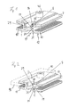
- FIGS. 1 to 3 A first embodiment of an inventive terminal is in the FIGS. 1 to 3 shown.
- the embodiment of Figures 1 and 2 is formed as a middle clamp for fixing two plate elements and accordingly has two elastomer profiles 10, 10 'for receiving a respective plate element.
- a plate element 90 is only in FIG. 2 and there also shown only in the second elastomeric profile 10 '.
- the clamp of FIG. 1 is essentially mirror-symmetrical. Therefore, in the following only the elastomer profile 10 shown in the figures on the right and its arrangement will be described in detail.
- the second elastomeric profile 10 ' is designed and arranged analogously.
- the illustrated clamp has a first clamp part 1 and a second clamp part 2, which are displaceable relative to one another in the vertical direction.
- a screw 40 which serves to clamp the two clamp parts 1 and 2.
- the head of the screw 40 abuts the second terminal part 2.
- the screw with a rail nut 41 ( Fig. 3 ), which is arranged adjacent to the first clamping part 1.
- the rail nut 41 is used for positive fixing of the two terminal parts 1 and 2 on a C-rail 45th
- two web-shaped projections 29 are provided, which extend in the vertical direction parallel to the screw 40 to the second terminal part 2 out and form a stop for the second terminal part 2.
- abut the two projections 29 on the second terminal part 2 while they are in the open position ( Fig. 1 ) are spaced from the second terminal part 2.
- the elastomer profile 10 (as well as the symmetrically constructed elastomeric profile 10 ') has a cross-sectionally U-shaped region 12, which serves for inserting a plate element 90.
- the elastomer profile 10 is provided with a wave structure which forms a contact surface for the plate element 90.
- the elastomer profile 10 has a cross-sectionally T-shaped region 17. This T-shaped area 17 adjoins the middle leg of the U-shaped area 12 at its center leg.
- the head of the T-shaped portion 17 is received in an insertion groove 25 which is delimited on the one hand by the web-shaped projection 29 and on the other hand by a first web 21 arranged on the clamping part 1 and by a second web 22 arranged on the clamping part 2.
- the elastomeric profile 10 is positively secured against lateral slipping out.
- the webs 21 and 22 are arranged vertically one above the other.
- clamping position clamp the two webs 21 and 22, the elastomeric profile 10 in a clamping portion 14, which is formed on the center leg of the T-shaped 17 area.
- the elastomeric profile 10 is secured against slipping in the longitudinal direction of the webs 21 and 22 and thus in the longitudinal direction of the clamping parts 1 and 2.
- the terminal parts 1, 2, however, in the in Fig. 1 illustrated open position so at least one of the terminal parts 1, 2, in particular at least one of the webs 21, 22, spaced from the clamping portion 14 (in the illustrated embodiment, the upper web 22 is spaced).
- the elastomeric profile 10 is thus released and can be moved along the webs 21, 22 for assembly purposes.
- the elastomer profile has in the clamping portion 14, ie in the middle leg of the T-shaped portion 17, a hole 19 which extends along the two webs 21, 22.
- This hole 19, which is arranged between the two webs 21 and 22, can at least absorb a portion of the deformations that occur when the elastomeric profile 10 is clamped in the clamping position by the two clamping parts 1, 2, and thus can at least reduce undesirable deformations of the elastomeric profile 10.
- the two clamp parts 1 and 2 each have horizontally extending wing regions, between which the two elastomer profiles 10 and 10 'are arranged.
- the elastomeric profile 10 At its second terminal part 2 side facing the elastomeric profile 10 has a preferably adjacent to the web 22 and / or along the web 22 extending spring lip 5, which is supported on the second terminal part 2.
- This spring lip 5, which is arranged at the transition from the middle leg to the side limb of the U-shaped region 12, presses the second clamp part 2 from the U-shaped region 12 of the elastomer profile 10 and thus from the first clamp part 1.
- the clamp parts 1 and 2 By the action of the spring lip 5 on the one hand the clamp parts 1 and 2 are held in the open position as long as the screw 40 is not tightened.
- the spring lip 5 biases over the screw 40, the rail nut 41 on the first terminal part 1, so that the rail nut 41 can be provisionally fixed in the C-rail 45 and has a provisional holding action before the screw 40 is tightened.
- FIG. 4 A further embodiment of a clamp according to the invention is shown in FIG Fig. 4 shown.
- the Fig. 4 illustrated embodiment differs from the embodiment of the FIGS. 1 to 3 in that according to Fig. 4 instead of two elastomer profiles 10 and 10 'only a single elastomeric profile 10 is provided. Accordingly, in the embodiment of the Fig. 4 around an edge clamp, which is intended for fixing a single plate member, whereas the embodiment of the FIGS. 1 to 3 a middle clamp holding two plate elements.
Landscapes
- Engineering & Computer Science (AREA)
- Chemical & Material Sciences (AREA)
- Life Sciences & Earth Sciences (AREA)
- Sustainable Development (AREA)
- Sustainable Energy (AREA)
- Thermal Sciences (AREA)
- Physics & Mathematics (AREA)
- Combustion & Propulsion (AREA)
- Mechanical Engineering (AREA)
- General Engineering & Computer Science (AREA)
- Clamps And Clips (AREA)
- Connection Of Plates (AREA)
- Roof Covering Using Slabs Or Stiff Sheets (AREA)
Abstract
Description
- Die Erfindung betrifft eine Klemme für zumindest ein Plattenelement, insbesondere für zumindest ein Photovoltaikmodul, vorzugsweise ein Dünnschicht-Photovoltaikmodul, gemäss dem Oberbegriff des Anspruchs 1. Eine gattungsgemässe Klemme ist ausgebildet mit einem ersten Klemmenteil und einem zweiten Klemmenteil, wobei die Klemmenteile relativ zueinander zwischen einer offenen Position und einer Klemmposition für das Plattenelement verstellbar sind, und zumindest einem Elastomerprofil, welches zur Anlage am Plattenelement zwischen den beiden Klemmenteilen angeordnet ist.
- Eine gattungsgemässe Klemme für Photovoltaikmodule geht aus der
WO 2009/086150 A1 hervor. Weitere Klemmen für Photovoltaikmodule sind aus derEP 2 090 847 A2 , derDE 20 2009 012 870 U1 und derDE 20 2009 014 048 U1 bekannt. - Es sind Klemmen für Photovoltaikmodule bekannt, bei denen das Photovoltaikmodul zwischen Elastomerelementen eingelegt wird, und die Elastomerelemente dann durch zwei Klemmenteile mit dem Photovoltaikmodul verpresst werden, wodurch das Photovoltaikmodul an den Klemmenteilen festgelegt wird.
- Es hat sich jedoch gezeigt, dass bestimmte Klemmen nach dem Stand der Technik unter Umständen ein unzureichendes Langzeit-Klemmverhalten aufweisen können.
- Aufgabe der Erfindung ist es, eine besonders zuverlässige, insbesondere im Langzeitbetrieb zuverlässige Klemme anzugeben.
- Die Aufgabe wird erfindungsgemäss durch eine Klemme mit den Merkmalen des Anspruchs 1 gelöst. Bevorzugte Ausführungsformen sind in den abhängigen Ansprüchen angegeben.
- Eine erfindungsgemässe Klemme ist dadurch gekennzeichnet, dass das Elastomerprofil einen Klemmabschnitt aufweist, der, insbesondere zum Festlegen des Elastomerprofils an den Klemmenteilen, zwischen den beiden Klemmenteilen eingeklemmt wird, wenn sich die Klemmenteile in der Klemmposition befinden. Das besagte Festlegen des Elastomerprofils an den Klemmenteilen kann insbesondere ein zumindest teilweise kraftschlüssiges Festlegen sein.
- Ein Grundgedanke der Erfindung liegt darin, dass das Elastomerprofil einen Klemmabschnitt aufweist, der unmittelbar (d.h. nicht über das Plattenelement) von den beiden Klemmenteilen eingeklemmt wird, wenn sich die beiden Klemmenteile in der Klemmposition befinden. Durch diese Verklemmung wird das Elastomerprofil mechanisch an den Klemmenteilen gesichert, so dass eine unerwünschte Verschiebung des Elastomerprofils relativ zu den Klemmenteilen, beispielsweise aufgrund unterschiedlicher thermischer Ausdehnung des Photovoltaikmoduls und seiner Tragestruktur, unterbunden wird. Eine Klebeverbindung, die eventuell alterungsanfällig sein kann und damit unter Umständen ein unzureichendes Langzeitverhalten aufweist, ist dabei nicht erforderlich.
- Die Geometrie der erfindungsgemässen Klemme beinhaltet, dass der Monteur das Elastomerprofil zwischen den beiden vorzugsweise metallischen Klemmenteilen verklemmt, wenn er die Klemme festzieht, d.h. wenn er die Klemmenteile in die Klemmposition verbringt. Hierdurch wird das Risiko, dass das Elastomerprofil während der Lebensdauer der Installation aufgrund dynamischer Effekte herausfällt, deutlich reduziert.
- Erfindungsgemäss wird unter der offenen Position eine Position verstanden, bei der das Plattenelement freigegeben ist, und/oder unter der Klemmposition eine Position, bei der die Klemme das Plattenelement hält.
- Die Klemmenteile sind geeigneterweise Metallteile, insbesondere Aluminiumteile. Es können aber auch Klemmenteile aus Kunststoff vorgesehen sein. Bei den Klemmenteilen kann es sich insbesondere um Strangpressprofile handeln.
- Besonders bevorzugt ist es, dass das Elastomerprofil einen im Querschnitt U-förmigen Bereich zum Umgreifen des Plattenelementes aufweist. Gemäss dieser Ausführungsform ist das oberseitig am Plattenelement anliegende Elastomerelement einstückig mit dem unterseitig am Plattenelement anliegenden Elastomerelement ausgebildet. Somit kann über den Klemmabschnitt, der sich vorzugsweise an den U-förmigen Bereich anschliesst, sowohl das oberseitig am Plattenelement anliegende Elastomerelement als auch das unterseitig am Plattenelement anliegende Elastomerelement gesichert werden. Zusätzliche Klebeverbindungen sind somit entbehrlich. Insbesondere ist es erfindungsgemäss, dass zwischen dem
- Elastomerprofil und den Klemmenteilen keine stoffschlüssige Verbindung, insbesondere keine Verklebung besteht, wodurch der Herstellungsaufwand weiter reduziert ist.
- Darüber hinaus ist es zweckmässig, dass das erste Klemmenteil einen Steg aufweist, der vom ersten Klemmenteil zum zweiten Klemmenteil hin vorsteht, und der den Klemmabschnitt klemmt, wenn sich die Klemmenteile in der Klemmposition befinden. Ein solcher Steg erlaubt es, eine besonders kleine Kontaktfläche mit dem Elastomerprofil und somit eine besonders gute Klemmwirkung zu realisieren. Aus analogen Erwägungen kann zusätzlich oder alternativ vorgesehen sein, dass das zweite Klemmenteil einen Steg aufweist, der vom zweiten Klemmenteil zum ersten Klemmenteil hin vorsteht, und der den Klemmabschnitt klemmt wenn sich die Klemmenteile in der Klemmposition befinden. Sofern zwei Stege vorgesehen sind, liegen diese Stege geeigneterweise übereinander, so dass die Stege das Elastomerprofil ähnlich den Backen einer Kneifzange bekneifen, wenn die beiden Klemmenteile in vertikaler Richtung zueinander verstellt und in die Klemmposition gebracht werden.
- Geeigneterweise weist das Elastomerprofil einen im Querschnitt T-förmigen Bereich auf. Ein solcher T-förmiger Bereich erlaubt es, eine formschlüssige Verbindung zwischen dem Elastomerprofil und den Klemmenteilen zu bilden, welche das Elastomerprofil zusätzlich sichert. Bevorzugt ist es, dass sich zumindest ein Teil des Klemmabschnitts am T-förmigen Bereich, insbesondere am Mittelschenkel des T-förmigen Bereichs befindet, wodurch eine besonders kompakte Anordnung erhalten wird.
- Darüber hinaus liegt eine bevorzugte Ausführungsform darin, dass die beiden Klemmenteile mit den beiden Stegen eine Einlegenut bilden, in die der im Querschnitt T-förmige Bereich des Elastomerprofils aufgenommen ist. Gemäss dieser Ausführungsform dienen die Stege nicht nur zum Klemmen des Elastomerprofils, sondern auch zum formschlüssigen Halten des T-förmigen Bereichs des Elastomerprofils, so dass die Baugrösse der Klemme weiter verringert werden kann.
- Eine weitere bevorzugte Ausgestaltung der Erfindung liegt darin, dass das Elastomerprofil im Bereich des Klemmabschnitts und/oder im Mittelschenkel des T-förmigen Bereichs zumindest ein Loch aufweist. Ein solches Loch kann beim Verklemmen des Klemmabschnitts auftretende Deformationen aufnehmen und für eine besonders gut definierte Verformungen sorgen. Das zumindest eine Loch kann insbesondere längs des zumindest einen Steges verlaufen, was unter anderem im Hinblick auf den Herstellungsaufwand vorteilhaft sein kann.
- Weiterhin kann nach der Erfindung vorgesehen sein, dass am ersten Klemmenteil zumindest ein Vorsprung angeordnet ist, der, insbesondere in vertikaler Richtung, zum zweiten Klemmenteil hin weist, der eine, insbesondere vertikale, Bewegung des zweiten Klemmenteils zum ersten Klemmenteil hin begrenzt, und der in der Klemmposition am zweiten Klemmenteil anliegt. Ein solcher Vorsprung bildet einerseits einen Anschlag, der den Klemmvorgang begrenzt und somit das Plattenelement vor Überlastung schützt. Anderseits definiert der Vorsprung die Klemmposition, so dass eine besonders zuverlässige Montage gegeben ist.
- Eine weitere vorteilhafte Ausgestaltung der Erfindung liegt darin, dass das Elastomerprofil eine Federlippe aufweist, welche vorzugsweise am im Querschnitt U-förmigen Bereich angeordnet ist, und welche vorzugsweise die Klemmenteile vorspannt und/oder in der offenen Position hält. Da die Federlippe die Klemmenteile offen hält, ist eine besonders einfache Montage der Klemme möglich. Die Federlippe ist zweckmässigerweise einstückig mit dem Elastomerprofil ausgebildet, so dass besonders ein besonders geringer Herstellungsaufwand gegeben ist.
- Weiterhin ist es bevorzugt, dass durch die beiden Klemmenteile eine Schraube hindurchgeführt ist, die mit einer Schienenmutter zum Festlegen der Klemme an einer Schiene, insbesondere an einer C-Profilschiene, gekontert ist. Gemäss dieser Ausführungsform können durch Festziehen der Schraube sowohl die beiden Klemmenteile aus der offenen Position in die Klemmposition gebracht werden als auch die Klemme an einer Profilschiene festgelegt werden, was eine besonders schnelle Montage ermöglicht. Darüber hinaus kann die Federlippe die Schienenmutter gegenüber dem der Schienenmutter benachbarten Klemmenteil vorspannen. Hierdurch wird eine vorläufige Montageposition zur Verfügung gestellt, in welcher die Klemme an der Schiene durch die von der Federlippe aufgebrachte Vorspannung vorläufig hält, so dass die Klemme vom Monteur nicht mehr festgehalten werden muss. Bei der Montage positioniert der Monteur also die Klemme so an der Schiene, dass sich die Schienenmutter im Kanal der Schiene befindet und dreht sodann die Schienenmutter um 90°, so dass sie quer zum Kanal verläuft. Die von der Federlippe über die Schraube auf die Schienenmutter aufgebrachte Vorspannung hält die Klemme vorläufig an der Schiene, so dass der Monteur die Klemme nun loslassen kann und das Plattenelement mit beiden Händen in die Klemme einführen kann. Durch Festziehen der Schraube kann der Monteur sodann sowohl das Plattenelement an der Klemme sichern als auch die Klemme endgültig an der Schiene sichern.
- Die Erfindung wird nachfolgend anhand bevorzugter Ausführungsbeispiele näher erläutert, die schematisch in den beiliegenden Figuren dargestellt sind. In den Figuren zeigen:
- Figur 1:
- eine perspektivische Darstellung einer ersten Ausführungsform einer erfindungsgemässen Klemme in der offenen Position;
- Figur 2:
- eine perspektivische Darstellung der Ausführungsform aus
Fig. 1 in der Klemmposition; - Figur 3:
- eine perspektivische Darstellung der Ausführungsform aus
Fig. 1 in der Klemmposition von schräg unten; - Figur 4:
- eine perspektivische Darstellung einer zweiten Ausführungsform einer erfindungsgemässen Klemme in der offenen Position; und
- Figur 5:
- eine schematische Querschnittsansicht einer erfindungsgemässen Klemme an einer C-Profilschiene.
- Ein erstes Ausführungsbeispiel einer erfindungsgemässen Klemme ist in den
Figuren 1 bis 3 dargestellt. Das Ausführungsbeispiel derFiguren 1 und 2 ist als Mittelklemme zum Fixieren von zwei Plattenelementen ausgebildet und weist demgemäss zwei Elastomerprofile 10, 10' zur Aufnahme jeweils eines Plattenelementes auf. Der Übersichtlichkeit halber ist ein solches Plattenelement 90 nur inFigur 2 und dort auch nur im zweiten Elastomerprofil 10' dargestellt. - Die Klemme der
Figur 1 ist im Wesentlichen spiegelsymmetrisch ausgebildet. Daher wird im Folgenden nur das in den Figuren rechts dargestellte Elastomerprofil 10 und dessen Anordnung im Detail beschrieben. Das zweite Elastomerprofil 10' ist analog ausgebildet und angeordnet. - Die dargestellte Klemme weist ein erstes Klemmenteil 1 und ein zweites Klemmenteil 2 auf, die in vertikaler Richtung zueinander verschiebbar sind. Durch die beiden Klemmenteile 1 und 2 läuft in vertikaler Richtung eine Schraube 40 hindurch, die zum Verspannen der beiden Klemmenteile 1 und 2 dient. Der Kopf der Schraube 40 liegt am zweiten Klemmenteil 2 an. An ihrem Schaft ist die Schraube mit einer Schienenmutter 41 (
Fig. 3 ) gekontert, die benachbart zum ersten Klemmenteil 1 angeordnet ist. Wie inFigur 5 schematisch dargestellt ist, dient die Schienenmutter 41 zum formschlüssigen Festlegen der beiden Klemmenteile 1 und 2 an einer C-Profilschiene 45. - Durch Festziehen der Schraube 40 können die beiden Klemmenteile 1, 2 relativ zueinander aus einer offenen Position, die in
Fig. 1 dargestellt ist, und in der die Plattenelemente 90 freigegeben sind, in eine Klemmposition verschoben werden, die inFig. 2 dargestellt ist, und in der die Plattenelemente 90 in den Elastomerprofilen 10, 10' festgelegt sind. Gleichzeitig kann durch Festziehen der Schraube 40 die Schienenmutter in der C-Profilschiene 45 festgelegt werden. - Am ersten Klemmenteil 1 sind zwei stegförmige Vorsprünge 29 vorgesehen, die sich in vertikaler Richtung parallel zur Schraube 40 zum zweiten Klemmenteil 2 hin erstrecken und einen Anschlag für das zweite Klemmenteil 2 bilden. In der Klemmposition (
Fig. 2 ) liegen die beiden Vorsprünge 29 am zweiten Klemmenteil 2 an, währen sie in der offenen Position (Fig. 1 ) vom zweiten Klemmenteil 2 beabstandet sind. - Das Elastomerprofil 10 (sowie auch das symmetrisch aufgebaute Elastomerprofil 10') weist einen im Querschnitt U-förmigen Bereich 12 auf, der zum Einlegen eines Plattenelementes 90 dient. Im Bereich der Seitenschenkel des U-förmigen Bereiches 12 ist das Elastomerprofil 10 mit einer Wellenstruktur versehen, die eine Kontaktfläche für das Plattenelement 90 bildet. Darüber hinaus weist das Elastomerprofil 10 einen im Querschnitt T-förmigen Bereich 17 auf. Dieser T-förmige Bereich 17 schliesst sich an seinem Mittelschenkel an den Mittelschenkel des U-förmigen Bereichs 12 an.
- Der Kopf des T-förmigen Bereichs 17 ist in einer Einlegenut 25 aufgenommen, die einerseits vom stegförmigen Vorsprung 29 und andererseits von einem am Klemmenteil 1 angeordneten ersten Steg 21 sowie von einem am Klemmenteil 2 angeordneten zweiten Steg 22 begrenzt wird. Durch die Aufnahme des T-förmigen Bereichs 17 in der Einlegenut 25 ist das Elastomerprofil 10 formschlüssig gegen ein seitliches Herausrutschen gesichert.
- Die Stege 21 und 22 sind vertikal übereinander angeordnet. In der in
Fig. 2 dargestellten Klemmposition klemmen die beiden Stege 21 und 22 das Elastomerprofil 10 in einem Klemmabschnitt 14 ein, der am Mittelschenkel des T-förmigen 17 Bereiches ausgebildet ist. Durch dieses Einklemmen des Klemmabschnitts 14 wird das Elastomerprofil 10 gegen ein Verrutschen in Längsrichtung der Stege 21 und 22 und somit in Längsrichtung der Klemmenteile 1 und 2 gesichert. Befinden sich die Klemmenteile 1, 2 hingegen in der inFig. 1 dargestellten offenen Position, so ist zumindest eines der Klemmenteile 1, 2, insbesondere zumindest einer der Stege 21, 22, vom Klemmabschnitt 14 beabstandet (im dargestellten Ausführungsbeispiel ist der obere Steg 22 beabstandet). Das Elastomerprofil 10 ist damit freigegeben und kann zu Montagezwecken längs der Stege 21, 22 verschoben werden. - Das Elastomerprofil weist im Klemmabschnitt 14, also im Mittelschenkel des T-förmigen Bereichs 17, ein Loch 19 auf, welches sich längs der beiden Stege 21, 22 erstreckt. Dieses Loch 19, welches zwischen den beiden Stegen 21 und 22 angeordnet ist, kann zumindest einen Teil der Deformationen aufnehmen, die auftreten, wenn das Elastomerprofil 10 in der Klemmposition durch die beiden Klemmteile 1, 2 eingeklemmt wird, und kann somit unerwünschte Deformationen des Elastomerprofils 10 zumindest reduzieren.
- Die beiden Klemmenteile 1 und 2 weisen jeweils horizontal verlaufende Flügelbereiche auf, zwischen denen die beiden Elastomerprofile 10 und 10' angeordnet sind.
- An seiner dem zweiten Klemmenteil 2 zugewandten Seite weist das Elastomerprofil 10 eine vorzugsweise benachbart zum Steg 22 angeordnete und/oder längs des Steges 22 verlaufende Federlippe 5 auf, die sich am zweiten Klemmenteil 2 abstützt. Diese Federlippe 5, die am Übergang vom Mittelschenkel zum Seitenschenkel des U-förmigen Bereichs 12 angeordnet ist, drückt das zweiten Klemmenteil 2 vom U-förmigen Bereich 12 des Elastomerprofils 10 und damit vom ersten Klemmenteil 1 ab. Durch die Aktion der Federlippe 5 werden zum einen die Klemmenteile 1 und 2 in der offenen Position gehalten solange die Schraube 40 nicht angezogen ist. Zum anderen spannt die Federlippe 5 über die Schraube 40 die Schienenmutter 41 am ersten Klemmenteil 1 vor, so dass die Schienenmutter 41 in der C-Profilschiene 45 vorläufig festgelegt werden kann und eine vorläufige Haltewirkung hat, bevor die Schraube 40 angezogen wird.
- Ein weiteres Ausführungsbeispiel einer erfindungsgemässen Klemme ist in
Fig. 4 dargestellt. Die inFig. 4 dargestellte Ausführungsform unterscheidet sich von der Ausführungsform derFiguren 1 bis 3 dadurch, dass gemässFig. 4 anstatt zweier Elastomerprofile 10 und 10' lediglich ein einziges Elastomerprofil 10 vorgesehen ist. Demgemäss handelt es sich bei der Ausführungsform derFig. 4 um eine Randklemme, die zum Festlegen eines einzelnen Plattenelementes vorgesehen ist, wohingegen die Ausführungsform derFiguren 1 bis 3 eine Mittelklemme ist, welche zwei Plattenelemente hält.
Claims (9)
- Klemme für zumindest ein Plattenelement (90), mit
einem ersten Klemmenteil (1) und einem zweiten Klemmenteil (2), wobei die Klemmenteile (1, 2) relativ zueinander zwischen einer offenen Position und einer Klemmposition für das Plattenelement (90) verstellbar sind, und
zumindest einem Elastomerprofil (10), welches zur Anlage am Plattenelement (90) zwischen den beiden Klemmenteilen (1, 2) angeordnet ist,
dadurch gekennzeichnet,
dass das Elastomerprofil (10) einen Klemmabschnitt (14) aufweist, der zwischen den beiden Klemmenteilen (1, 2) eingeklemmt wird, wenn sich die Klemmenteile (1, 2) in der Klemmposition befinden. - Klemme nach Anspruch 1,
dadurch gekennzeichnet,
dass das Elastomerprofil (10) einen im Querschnitt U-förmigen Bereich (12) zum Umgreifen des Plattenelementes (90) aufweist. - Klemme nach einem der vorstehenden Ansprüche,
dadurch gekennzeichnet,
dass das erste Klemmenteil (1) einen Steg (21) aufweist, der vom ersten Klemmenteil (1) zum zweiten Klemmenteil (2) hin vorsteht, und der den Klemmabschnitt (14) klemmt, wenn sich die Klemmenteile (1, 2) in der Klemmposition befinden und/oder dass das zweite Klemmenteil (2) einen Steg (22) aufweist, der vom zweiten Klemmenteil (2) zum ersten Klemmenteil (1) hin vorsteht, und der den Klemmabschnitt (14) klemmt wenn sich die Klemmenteile (1, 2) in der Klemmposition befinden. - Klemme nach einem der vorstehenden Ansprüche,
dadurch gekennzeichnet,
dass das Elastomerprofil (10) einen im Querschnitt T-förmigen Bereich (17) aufweist, und dass sich zumindest ein Teil des Klemmabschnitts (14) am Mittelschenkel des T-förmigen Bereichs (17) befindet. - Klemme nach Anspruch 3 und 4,
dadurch gekennzeichnet,
dass die beiden Klemmenteile (1, 2) mit den beiden Stegen (21, 22) eine Einlegenut (25) bilden, in die der im Querschnitt T-förmige Bereich (17) des Elastomerprofils (10) aufgenommen ist. - Klemme nach einem der vorstehenden Ansprüche,
dadurch gekennzeichnet,
dass das Elastomerprofil (10) im Bereich des Klemmabschnitts (14) zumindest ein Loch (19) aufweist. - Klemme nach einem der vorstehenden Ansprüche,
dadurch gekennzeichnet,
dass am ersten Klemmenteil (1) zumindest ein Vorsprung (29) angeordnet ist, der zum zweiten Klemmenteil (2) hin weist, der eine Bewegung des zweiten Klemmenteils (2) zum ersten Klemmenteils (1) hin begrenzt, und der in der Klemmposition am zweiten Klemmenteil (2) anliegt. - Klemme nach einem der vorstehenden Ansprüche,
dadurch gekennzeichnet,
dass das Elastomerprofil (10) eine Federlippe (5) aufweist, welche am im Querschnitt U-förmigen Bereich (12) angeordnet ist, und welche die Klemmenteile (1, 2) vorspannt. - Klemme nach einem der vorstehenden Ansprüche,
dadurch gekennzeichnet,
dass durch die beiden Klemmenteile (1, 2) eine Schraube (40) hindurchgeführt ist, die mit einer Schienenmutter (41) zum Festlegen der Klemme an einer Schiene (45) gekontert ist.
Applications Claiming Priority (1)
| Application Number | Priority Date | Filing Date | Title |
|---|---|---|---|
| DE102010062384A DE102010062384A1 (de) | 2010-12-03 | 2010-12-03 | Klemme für ein Plattenelement, insbesondere für ein Photovoltaikmodul |
Publications (2)
| Publication Number | Publication Date |
|---|---|
| EP2461119A2 true EP2461119A2 (de) | 2012-06-06 |
| EP2461119A3 EP2461119A3 (de) | 2015-11-25 |
Family
ID=45346217
Family Applications (1)
| Application Number | Title | Priority Date | Filing Date |
|---|---|---|---|
| EP11188538.0A Withdrawn EP2461119A3 (de) | 2010-12-03 | 2011-11-10 | Klemme für ein Plattenelement, insbesondere für ein Photovoltaikmodul |
Country Status (8)
| Country | Link |
|---|---|
| US (1) | US20120138764A1 (de) |
| EP (1) | EP2461119A3 (de) |
| JP (1) | JP2012117672A (de) |
| CN (1) | CN102536978A (de) |
| AU (1) | AU2011253841B2 (de) |
| CA (1) | CA2759966A1 (de) |
| DE (1) | DE102010062384A1 (de) |
| ZA (1) | ZA201108890B (de) |
Cited By (1)
| Publication number | Priority date | Publication date | Assignee | Title |
|---|---|---|---|---|
| EP3098538A1 (de) * | 2015-05-29 | 2016-11-30 | Armin Sanavi | Solarmodulhalteanordnung |
Families Citing this family (42)
| Publication number | Priority date | Publication date | Assignee | Title |
|---|---|---|---|---|
| US7434362B2 (en) * | 2001-07-20 | 2008-10-14 | Unirac, Inc. | System for removably and adjustably mounting a device on a surface |
| US9160273B2 (en) * | 2011-07-08 | 2015-10-13 | Unirac, Inc. | Universal end clamp |
| DE102011111449B4 (de) * | 2011-08-30 | 2014-07-17 | Carl Freudenberg Kg | Klemmmverbindung zur Befestigung von plattenförmigen Bauelementen insbesondere von Solarmodulen |
| WO2014032076A1 (en) * | 2012-08-29 | 2014-03-06 | Westblade Illustration Pty Ltd | Holder such as for a learner/probationary driver plate or the like |
| US10008975B2 (en) | 2012-12-10 | 2018-06-26 | Nextracker Inc. | Clamp assembly for solar tracker |
| US9766319B2 (en) | 2012-12-10 | 2017-09-19 | Nextracker Inc. | Off-set drive assembly for solar tracker |
| DE112013005890T5 (de) | 2012-12-10 | 2015-09-10 | Nextracker Inc. | Horizontaler ausgeglichener Solarnachführer |
| US9466749B1 (en) * | 2012-12-10 | 2016-10-11 | Nextracker Inc. | Balanced solar tracker clamp |
| DE202012012462U1 (de) * | 2012-12-20 | 2013-03-04 | Mounting Systems Gmbh | Befestigungssystem zur Montage von Solarmodulen |
| CN102995848B (zh) * | 2012-12-26 | 2015-07-29 | 上海亚泽金属屋面系统股份有限公司 | 一种彩钢板转接夹具 |
| CN103107220B (zh) * | 2012-12-31 | 2015-10-07 | 友达光电股份有限公司 | 光伏装置、光伏模块及其固定件 |
| CN103066138B (zh) * | 2013-01-08 | 2015-03-11 | 羲和太阳能电力有限公司 | 一种光伏组件安装夹具 |
| US20140252187A1 (en) * | 2013-02-05 | 2014-09-11 | Cody Petrovic | Modular mounting system using picatinny-type rail |
| US9011034B2 (en) * | 2013-03-10 | 2015-04-21 | Sunmodo Corporation | Seam clamp for solar panel and rooftop objects |
| US20160168867A1 (en) * | 2013-05-09 | 2016-06-16 | David Chester | A deck fastening system |
| US12301159B2 (en) | 2014-11-13 | 2025-05-13 | Unirac Inc. | Modular sloped roof solar mounting system |
| US9825581B2 (en) | 2013-11-14 | 2017-11-21 | Ecolibrium Solar, Inc. | Modular sloped roof solar mounting system |
| US9531319B2 (en) | 2013-12-23 | 2016-12-27 | Sunpower Corporation | Clamps for solar systems |
| US9985575B2 (en) | 2014-04-07 | 2018-05-29 | Rillito River Solar, Llc | Height adjustment bracket for roof applications |
| US9431953B2 (en) * | 2014-10-31 | 2016-08-30 | Rillito River Solar, Llc | Height adjustment bracket for roof applications |
| US12107530B2 (en) | 2014-04-07 | 2024-10-01 | EcoFasten Solar, LLC | Height adjustment bracket for roof applications |
| WO2016094795A1 (en) * | 2014-12-11 | 2016-06-16 | A.K. Stamping Company, Inc. | Grounding clamps |
| CN104579145B (zh) * | 2015-01-09 | 2017-07-28 | 浙江宏阳新能源科技有限公司 | 一种易拆洗的太阳能收集装置 |
| DE102015202596B3 (de) | 2015-02-12 | 2016-06-16 | Solibro Hi-Tech Gmbh | Klemmvorrichtung und Verfahren zur Montage eines Solarmoduls |
| US10312853B2 (en) | 2015-03-11 | 2019-06-04 | Ecolibrium Solar, Inc | Sloped roof solar panel mounting system |
| US10340837B2 (en) | 2015-03-11 | 2019-07-02 | Ecolibrium Solar, Inc | Sloped roof solar panel mounting system |
| US10756668B2 (en) | 2015-03-11 | 2020-08-25 | Ecouni, Llc | Universal sloped roof solar panel mounting system |
| US9543888B2 (en) * | 2015-06-09 | 2017-01-10 | Nextracker Inc. | Frameless solar module mounting |
| US9793852B2 (en) | 2015-07-15 | 2017-10-17 | Solarcity Corporation | Clamp and bowl mounting system for photovoltaic modules |
| US10187006B2 (en) * | 2015-07-15 | 2019-01-22 | Solarcity Corporation | Wedge spring clip mounting system for photovoltaic modules |
| US10469023B2 (en) | 2016-09-12 | 2019-11-05 | EcoFasten Solar, LLC | Roof mounting system |
| US9893677B1 (en) * | 2017-07-06 | 2018-02-13 | Sunmodo Corporation | Bottom clamp for mounting solar panels to roofs |
| US11018620B2 (en) * | 2018-09-24 | 2021-05-25 | Sunpower Corporation | Solar module skirt assembly |
| DE102018221291A1 (de) * | 2018-12-10 | 2020-06-10 | Zf Friedrichshafen Ag | Verbindungsvorrichtung, Verbindungselement, System und Verfahren |
| US11290053B2 (en) * | 2019-04-01 | 2022-03-29 | Unirac Inc. | Solar panel mounting apparatus |
| US11258400B2 (en) * | 2019-04-16 | 2022-02-22 | Unirac Inc. | Height adjustable solar panel mounting system |
| JP7393080B2 (ja) * | 2019-07-19 | 2023-12-06 | 積水アクアシステム株式会社 | 結合下水用傾斜板、および結合部材の取り付け方法 |
| CN110337961A (zh) * | 2019-08-20 | 2019-10-18 | 厦门农丰园大棚开发有限公司 | 一种光伏农业大棚 |
| CN110454997B (zh) * | 2019-09-10 | 2024-06-11 | 浙江正泰新能源开发有限公司 | 光伏组件快装固定结构 |
| USD1079430S1 (en) * | 2022-09-19 | 2025-06-17 | EcoFasten Solar, LLC | Wire clamp |
| US20250286498A1 (en) * | 2024-03-06 | 2025-09-11 | Unirac, Inc. | Rail-less attachment roof mount |
| US20240266987A1 (en) * | 2024-03-08 | 2024-08-08 | Wencon Development, Inc., Dba Quick Mount Pv | Waterproofing Mounting System for Attaching Solar Modules to a Roof |
Citations (4)
| Publication number | Priority date | Publication date | Assignee | Title |
|---|---|---|---|---|
| WO2009086150A1 (en) | 2007-12-21 | 2009-07-09 | Unirac, Inc. | Soft-faced clamp for photovoltaic frameless modules and laminates |
| EP2090847A2 (de) | 2008-02-13 | 2009-08-19 | HILTI Aktiengesellschaft | Befestigungsvorrichtung für die Befestigung von plattenförmigen Elementen, z.B. Solarpaneele |
| DE202009012870U1 (de) | 2009-08-21 | 2010-01-21 | Vm Edelstahltechnik Gmbh | Haltevorrichtung für plattenförmige Elemente |
| DE202009014048U1 (de) | 2009-10-15 | 2010-02-11 | Vm Edelstahltechnik Gmbh | Klemmvorrichtung für plattenförmige Elemente |
Family Cites Families (13)
| Publication number | Priority date | Publication date | Assignee | Title |
|---|---|---|---|---|
| US3028938A (en) * | 1959-03-12 | 1962-04-10 | Schorr Wallace | Locked joint and reinforcing construction for fragile sheet material |
| DE2825726C3 (de) * | 1978-06-12 | 1980-12-04 | Gebr. Happich Gmbh, 5600 Wuppertal | Profilleiste aus Gummi oder Kunststoff |
| US5356675A (en) * | 1992-12-28 | 1994-10-18 | Unger Frederick C | Glazing system |
| FR2827420B1 (fr) * | 2001-07-10 | 2006-08-11 | Ifm Electronic Gmbh | Dispositif de fixation pour des detecteurs tels que des capteurs de proximite |
| US6672018B2 (en) * | 2001-10-12 | 2004-01-06 | Jefferson Shingleton | Solar module mounting method and clip |
| DE202007008659U1 (de) * | 2007-06-18 | 2007-08-23 | Solarmarkt Ag | Solarmodul-Montagesystem |
| DE202007016861U1 (de) * | 2007-11-30 | 2008-05-08 | Solarpower Gmbh | Klemmverbindung für flächige Bauteile |
| SE531927C2 (sv) * | 2008-01-25 | 2009-09-08 | Brunkeberg Industriutveckling Ab | Profil för en flervåningsbyggnads fasad och en flervåningsbyggnad med en sådan fasad |
| CN201374339Y (zh) * | 2008-11-20 | 2009-12-30 | 福建钧石能源有限公司 | 太阳能电池安装钳组件 |
| US8240109B2 (en) * | 2009-03-20 | 2012-08-14 | Northern States Metals Company | Support system for solar panels |
| DE102009039791A1 (de) * | 2009-09-02 | 2011-03-17 | Adensis Gmbh | Zum Einsatz für Montageroboter geeignete Modulklemme für Photovoltaikmodule |
| US8156697B2 (en) * | 2009-10-15 | 2012-04-17 | Sunlink Corporation | Photovoltaic module mounting system |
| DE202009015056U1 (de) * | 2009-11-05 | 2010-03-04 | Vm Edelstahltechnik Gmbh | Klemmvorrichtung für plattenförmige Elemente |
-
2010
- 2010-12-03 DE DE102010062384A patent/DE102010062384A1/de not_active Withdrawn
-
2011
- 2011-11-10 EP EP11188538.0A patent/EP2461119A3/de not_active Withdrawn
- 2011-11-30 CA CA2759966A patent/CA2759966A1/en not_active Abandoned
- 2011-11-30 CN CN2011103996326A patent/CN102536978A/zh active Pending
- 2011-12-01 JP JP2011263749A patent/JP2012117672A/ja active Pending
- 2011-12-02 ZA ZA2011/08890A patent/ZA201108890B/en unknown
- 2011-12-02 US US13/309,624 patent/US20120138764A1/en not_active Abandoned
- 2011-12-05 AU AU2011253841A patent/AU2011253841B2/en not_active Ceased
Patent Citations (4)
| Publication number | Priority date | Publication date | Assignee | Title |
|---|---|---|---|---|
| WO2009086150A1 (en) | 2007-12-21 | 2009-07-09 | Unirac, Inc. | Soft-faced clamp for photovoltaic frameless modules and laminates |
| EP2090847A2 (de) | 2008-02-13 | 2009-08-19 | HILTI Aktiengesellschaft | Befestigungsvorrichtung für die Befestigung von plattenförmigen Elementen, z.B. Solarpaneele |
| DE202009012870U1 (de) | 2009-08-21 | 2010-01-21 | Vm Edelstahltechnik Gmbh | Haltevorrichtung für plattenförmige Elemente |
| DE202009014048U1 (de) | 2009-10-15 | 2010-02-11 | Vm Edelstahltechnik Gmbh | Klemmvorrichtung für plattenförmige Elemente |
Cited By (1)
| Publication number | Priority date | Publication date | Assignee | Title |
|---|---|---|---|---|
| EP3098538A1 (de) * | 2015-05-29 | 2016-11-30 | Armin Sanavi | Solarmodulhalteanordnung |
Also Published As
| Publication number | Publication date |
|---|---|
| AU2011253841B2 (en) | 2013-04-04 |
| JP2012117672A (ja) | 2012-06-21 |
| US20120138764A1 (en) | 2012-06-07 |
| CA2759966A1 (en) | 2012-06-03 |
| AU2011253841A1 (en) | 2012-06-21 |
| CN102536978A (zh) | 2012-07-04 |
| DE102010062384A1 (de) | 2012-06-06 |
| ZA201108890B (en) | 2012-08-29 |
| EP2461119A3 (de) | 2015-11-25 |
Similar Documents
| Publication | Publication Date | Title |
|---|---|---|
| EP2461119A2 (de) | Klemme für ein Plattenelement, insbesondere für ein Photovoltaikmodul | |
| EP2009293B1 (de) | Vorrichtung zum Verbinden einer Profilschiene mit einem anderen Bauteil | |
| EP0528213B1 (de) | Beschlagteil zur Klemmbefestigung in einer mindestens einseitigen hinterschnittenen Profilnut | |
| EP2435768B1 (de) | Vorrichtung zur befestigung einer montageschiene an einem gewindeschaft | |
| EP0623490A2 (de) | Dachgepäckträger für Kraftfahrzeuge mit Dachreling | |
| EP2495507A1 (de) | Befestigungselement für Solarmodulrahmen | |
| DE102008000293A1 (de) | Befestigungsvorrichtung für die Befestigung von plattenförmigen Elementen | |
| EP2425188A2 (de) | Vorrichtung zur befestigung einer tragschiene an einem dachhaken | |
| EP2527762A1 (de) | Befestigungsvorrichtung | |
| DE102010031874A1 (de) | Einrichtung zum Befestigen eines Gegenstands an einem eine berandete Öffnung aufweisenden Bauteil | |
| DE102020206810B3 (de) | Montagesystem, Montageanordnung und Solaranlage | |
| EP3623722A1 (de) | Dachhaken | |
| EP2249102A2 (de) | Verbinder für eine Profilschiene | |
| DE69812087T2 (de) | Längliches befestigungselement für platten | |
| EP2253902B1 (de) | Bauteilesatz für die Montage von Solarmodulen auf einem Dach | |
| DE202012006839U1 (de) | Befestigungsklemme für Solarmodule | |
| EP2372269A2 (de) | Verbindungsvorrichtung und Profilanordnung | |
| CH709045A2 (de) | Klemmsystem für Objekte mit mindestens einer glatten, ebenen oder planen sowie gleichmässigen geradlinigen Aussenkante oder Aussenseite. | |
| EP3241974B1 (de) | Anordnung für eine dichtung, insbesondere für eine auflaufdichtung oder für eine sich selbsttätig absenkende bodendichtung für türen | |
| DE202011005287U1 (de) | Klemmelement zur Befestigung von Solarmodulen und Befestigungseinrichtung | |
| AT525006B1 (de) | Montageprofil | |
| DE19521916A1 (de) | Vorrichtung zur Abdichtung zwischen beweglichen Anlagenteilen | |
| DE9403601U1 (de) | Tiefbauwinkel für Traggerüste für elektrische Verteileranlagen | |
| AT12657U1 (de) | System zum befestigen einer schiene auf einem untergrund | |
| DE102011017053B4 (de) | Klemmelement zur Befestigung von Solarmodulen und Befestigungseinrichtung |
Legal Events
| Date | Code | Title | Description |
|---|---|---|---|
| PUAI | Public reference made under article 153(3) epc to a published international application that has entered the european phase |
Free format text: ORIGINAL CODE: 0009012 |
|
| AK | Designated contracting states |
Kind code of ref document: A2 Designated state(s): AL AT BE BG CH CY CZ DE DK EE ES FI FR GB GR HR HU IE IS IT LI LT LU LV MC MK MT NL NO PL PT RO RS SE SI SK SM TR |
|
| AX | Request for extension of the european patent |
Extension state: BA ME |
|
| PUAL | Search report despatched |
Free format text: ORIGINAL CODE: 0009013 |
|
| AK | Designated contracting states |
Kind code of ref document: A3 Designated state(s): AL AT BE BG CH CY CZ DE DK EE ES FI FR GB GR HR HU IE IS IT LI LT LU LV MC MK MT NL NO PL PT RO RS SE SI SK SM TR |
|
| AX | Request for extension of the european patent |
Extension state: BA ME |
|
| RIC1 | Information provided on ipc code assigned before grant |
Ipc: F24J 2/46 20060101ALI20151021BHEP Ipc: H01L 31/042 20140101ALI20151021BHEP Ipc: F24J 2/52 20060101AFI20151021BHEP |
|
| STAA | Information on the status of an ep patent application or granted ep patent |
Free format text: STATUS: THE APPLICATION IS DEEMED TO BE WITHDRAWN |
|
| 18D | Application deemed to be withdrawn |
Effective date: 20160526 |