EP2461221A2 - Appareil de commande avec des entrées destinées au traitement de signaux provenant de types de capteurs différents - Google Patents
Appareil de commande avec des entrées destinées au traitement de signaux provenant de types de capteurs différents Download PDFInfo
- Publication number
- EP2461221A2 EP2461221A2 EP11189768A EP11189768A EP2461221A2 EP 2461221 A2 EP2461221 A2 EP 2461221A2 EP 11189768 A EP11189768 A EP 11189768A EP 11189768 A EP11189768 A EP 11189768A EP 2461221 A2 EP2461221 A2 EP 2461221A2
- Authority
- EP
- European Patent Office
- Prior art keywords
- input
- pull
- switch
- input terminal
- sensor
- Prior art date
- Legal status (The legal status is an assumption and is not a legal conclusion. Google has not performed a legal analysis and makes no representation as to the accuracy of the status listed.)
- Granted
Links
Images



Classifications
-
- G—PHYSICS
- G05—CONTROLLING; REGULATING
- G05B—CONTROL OR REGULATING SYSTEMS IN GENERAL; FUNCTIONAL ELEMENTS OF SUCH SYSTEMS; MONITORING OR TESTING ARRANGEMENTS FOR SUCH SYSTEMS OR ELEMENTS
- G05B19/00—Program-control systems
- G05B19/02—Program-control systems electric
- G05B19/04—Program control other than numerical control, i.e. in sequence controllers or logic controllers
- G05B19/042—Program control other than numerical control, i.e. in sequence controllers or logic controllers using digital processors
- G05B19/0423—Input/output
-
- H—ELECTRICITY
- H03—ELECTRONIC CIRCUITRY
- H03K—PULSE TECHNIQUE
- H03K17/00—Electronic switching or gating, i.e. not by contact-making and –breaking
- H03K17/51—Electronic switching or gating, i.e. not by contact-making and –breaking characterised by the components used
- H03K17/56—Electronic switching or gating, i.e. not by contact-making and –breaking characterised by the components used by the use, as active elements, of semiconductor devices
- H03K17/60—Electronic switching or gating, i.e. not by contact-making and –breaking characterised by the components used by the use, as active elements, of semiconductor devices the devices being bipolar transistors
-
- G—PHYSICS
- G05—CONTROLLING; REGULATING
- G05B—CONTROL OR REGULATING SYSTEMS IN GENERAL; FUNCTIONAL ELEMENTS OF SUCH SYSTEMS; MONITORING OR TESTING ARRANGEMENTS FOR SUCH SYSTEMS OR ELEMENTS
- G05B2219/00—Program-control systems
- G05B2219/20—Pc systems
- G05B2219/21—Pc I-O input output
- G05B2219/21085—Define type of I-O, analog, digital, pulse
-
- G—PHYSICS
- G05—CONTROLLING; REGULATING
- G05B—CONTROL OR REGULATING SYSTEMS IN GENERAL; FUNCTIONAL ELEMENTS OF SUCH SYSTEMS; MONITORING OR TESTING ARRANGEMENTS FOR SUCH SYSTEMS OR ELEMENTS
- G05B2219/00—Program-control systems
- G05B2219/20—Pc systems
- G05B2219/21—Pc I-O input output
- G05B2219/21114—Universal input, AC or DC
Definitions
- the present invention relates to a set up for use in a motor vehicle control unit according to the preamble of claim 1.
- the invention relates to a method according to the preamble of the independent method claim.
- Such a control unit has at least one input with an input terminal, at least two input channels and an input circuit. It is set up to receive signals from a sensor via the input terminal and feed it via the input circuit into an input channel of the input, which is connected to a defined potential via a resistor.
- Such a method for adapting such a control device to a sensor to be connected to the control unit is also known per se, wherein the adjusting the Step of resistance-bonding the input terminal to a defined potential.
- Such control units process sensor signals and generate therefrom manipulated variables with which actuators of the motor vehicle are controlled in order to influence the behavior of the motor vehicle and / or of parts of the motor vehicle during operation.
- operating parameters of the motor vehicle for example, should be kept within a permitted range.
- the operating parameters are formed in physical quantities, which are detected by sensors and converted into electrical sensor signals.
- To transfer the electrical sensor signals to the control unit interfaces are required to convert the sensor signals provided by sensors into signals that can be processed by the control unit. Different sensors require different interfaces.
- the interfaces are usually integrated into the controller and have an input port, an input circuit and an input channel.
- the interfaces differ both with regard to their input circuit and with regard to the input channel.
- inputs of control devices differ, for example, in whether the defined potential has a comparatively larger value (for example five volts) or a comparatively high value smaller value (for example, zero volts) has.
- the defined potential serves to establish a reference potential with which, for example, error states can be detected.
- the connection to the comparatively lower potential occurs when the sensor is a power source. This is usually the case with an analog sensor.
- the connection to the comparatively higher potential occurs when the sensor represents a current sink. This is usually the case with a PWM sensor.
- an input channel with an ADC ie an analog-to-digital converter
- an input channel with a digital port is needed, which ideally has a capture / compare function.
- the headlight range control it must be possible, for example, to connect both analog sensors and PWM sensors.
- a control unit is assumed to be known, which has two input channels for one input.
- the controller is then populated with an input circuit that connects one of the two input channels to the input terminal of that input.
- ECUs of one type can be adapted to different vehicles, one variant of the ECU is required per variant.
- the various types of controllers differ from one another in the hardware of their input circuits.
- control units with input circuits which are individualized for different vehicle variants, is complex and makes it difficult to provide spare parts. Both drive the respective costs, be it for the production, or for spare parts, in the amount. Also, the supply of control devices to the vehicle during its manufacture is complicated because different vehicle variants are often manufactured on the same production line and therefore it must be ensured that each vehicle receives its right control unit.
- the object of the invention is to specify a control device in which the disadvantages mentioned do not occur.
- the object of the invention is to specify a method of the type mentioned, with which it is possible to avoid the disadvantages mentioned. This object is achieved by the features of the independent one with regard to their device aspects with the features of independent claim 1 and with regard to their method aspects
- controller allows the controller to be matched to sensors to be connected, which does not require changes to the ECU hardware, and instead takes place through pure control commands that alternatively close the pull-up switch or the pull-down switch of an input.
- the adaptation can be carried out, for example, in motor vehicle production by means of a tape end programming of the control unit.
- the same control units can be used for different equipment variants of vehicles with sensors to be connected.
- the logistics of vehicle manufacturing is simplified because only one type of control unit has to be processed and delivered at an assembly station in vehicle production.
- the simplifications also have an effect on the spare parts inventory because the invention reduces the number of control unit types to be provided as spare parts. All of this has a cost-cutting effect.
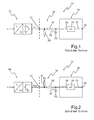
- FIG. 1 an analog sensor 10, which is connected to an input terminal 12 of a control unit 14.
- the analog sensor 10 is configured to detect a physical quantity ⁇ and to map it in an analog signal U, which is provided as an output signal of the analog sensor 10.
- the physical quantity ⁇ is a preferred embodiment, a tilt angle of a vehicle body or another physical quantity, in which the inclination of the vehicle body is reflected, for example, a deflection of a chassis part of the motor vehicle.
- the control unit 14 has a central area 16 and a peripheral area 18.
- the central area 16 has an input channel 20, an output channel 22 and a signal from the input channel 20 to output signals for the output channel 22 processing microcomputer 24 with computational and memory capabilities.
- the peripheral region 18 has an input circuit with which the analog signal U provided by the analog sensor 10 is processed such that it can be fed into the input channel 20 of the central region 16 of the control device 14.
- Analog sensors are usually power sources.
- the input circuit of the peripheral region 18 of the control device 14 of the FIG. 1 a pull-down resistor 26.
- the pull-down resistor 26 results in a de-energized state, ie when no analog sensor 10 is connected to the input terminal 12, a low potential in the form of the ground potential at the input terminal 12 and thus also at the input channel 20 of the central region 16.
- the input channel 20 is designed in this embodiment as an analog-to-digital converter (ADC).
- ADC analog-to-digital converter
- the input circuit of the peripheral region 18 also has a low pass of a resistor 28 and a capacitor 30 via the pull-down resistor 26. This low pass is used to filter the analog signals U and to protect against overvoltages.
- the microcomputer 24 processes the signals via the analog-to-digital converter (ADC) into digital signals converted signals of the analog sensor 10 and optionally further signals from in the FIG. 1 not shown sensors, using stored data and programs to a manipulated variable, which is provided via the output channel 22 at an output 32 of the central region 16 and / or the controller 14.
- a headlight range control such a manipulated variable is used to adjust the headlight range of a light module of a headlight of the motor vehicle, with which an undesired influence of a vehicle inclination on the headlight range is compensated.
- FIG. 2 shows a PWM sensor connected to an input terminal 12 of a controller 14.
- PWM sensors 34 detect a physical quantity ⁇ and map it in the duty cycle of a pulse width modulated signal PWM.
- PWM sensors 34 are typically current sink sensors.
- an input circuit is advantageous in which the input terminal 12 is connected via a pull-up resistor 36 to a comparatively higher potential.
- the comparatively higher potential may be a five volt potential if the comparatively lower potential is a ground potential at zero volts.
- a low-pass filter of a resistor 28 and a capacitor 30 is also used in the subject of FIG. 2 for filtering the input signals and for protecting the subsequent input channel 38 from overvoltages.
- the input channel 38 is at the subject of FIG. 2 preferably designed as a digital capture / compare function.
- a comparison of Figures 1 and 2 shows, that the topologies of the input circuits in the peripheral areas 18 differ both in terms of the component arrangement and in terms of the necessary resources in the central area 16 of the control unit 14. While one needs an ADC input channel 20 for the evaluation of an analog sensor 10, a digital port (ideally with capture / compare function) must be provided for the evaluation of a PWM sensor 34.
- FIG. 1 shows only one connected to the controller 14 sensor and thus each only one input.
- the controller 14 sensor Normally, there are 14 further sensor inputs in the evaluating control unit, wherein the number of inputs is greater than or equal to the number of sensors to be connected to the control unit 14.
- FIG. 3 shows, similar to FIG. 1 , an analog sensor 10, which is connected to an input terminal 12 of a likewise known control unit 40.
- the control unit 40 differs from the control unit 14 from the FIG. 1 in that it provides both an analog input channel 20 and a digital input channel 38 to an input terminal 12.
- the control unit 40 from the FIG. 3 offers so far already more flexibility than the control unit 14 from the FIG. 1 because it allows both a connection of an analog sensor 10, as well as a connection of a PWM sensor 34 to the same input terminal 12.
- the input terminal 12 is connected within the control unit 40 with an input circuit to the ADC input channel 20 of the central portion 16 of the control unit 40, as already described with reference to FIG. 1 has been explained.
- Input circuit is characterized in particular by the fact that the input terminal 12 is connected within the control unit 40 with the pull-down resistor 26 to a low potential, for example, the ground potential lying at zero volts.
- the input circuit connects the input terminal 12 within the controller 40 to the ADC input channel 20 and, in addition to the pull-down resistor 26, already described with reference to FIGS FIG. 1 explained low pass from a resistor 28 and a capacitor 30.
- FIG. 4 shows the controller 40 from the FIG. 3 with the alternative input circuit, already with reference to the FIG. 2 in particular, characterized in that the input terminal 12 is connected via a pull-up resistor 36 to a comparatively higher potential, for example a potential of five volts.
- This input circuit serves, as already with reference to the FIG. 2
- the input terminal 12 via the input circuit, which in the illustrated embodiment, in addition to the pull-up resistor 36 still has a low pass of a resistor 28 and a capacitor 30 , connected to the digital input channel (port) 38 of the central area 16 of the control unit 40.
- FIG. 5 shows a first embodiment of a control device 42 according to the invention.
- the control unit 42 is characterized in that its input circuit 43, which connects the input terminal 12 to the central region 16, a first, actuatable by the control unit 42 pull-up switch 44, the one Connection of the input terminal 12 controls to a high potential, and it is further characterized in that a Input circuit 43 has a second controllable by the controller 42 switch 46 which controls a connection of the input terminal to a low potential and therefore can be referred to as a pull-down switch 46.
- the high potential can in this embodiment and also in the still following embodiment, in the FIG. 6 is five volts without being set to such a value.
- the low potential can be zero volts without being set to such a value.
- Pull-up switch 44 is controlled in one embodiment via a dedicated digital port 48 controlled by microcomputer 24.
- the pull-down switch 46 is controlled in one embodiment via its own digital port 50 from the microcomputer 24.
- the control is carried out so that when one of the two switches 44, 46 is closed, the other switch is opened.
- the control of the two switches 44 and 46 is complementary to each other.
- the complementarity of the drive also makes it possible to control both switches 44 and 46 via one and the same port when the switches 44 and 46 are designed as mutually complementary switches of a CMOS logic.
- the one of the two switches 44 and 46 would then be as an NMOS transistor and the other of the two switches 44 and 46 would then be designed as a PMOS transistor.
- the two switches 44 and 46 are designed as complementary bipolar transistors, so one as a PNP transistor, and one as an NPN transistor. It is also preferable that the pull-up switch 44 is connected in series with the pull-up resistor 36 and that the pull-down switch 46 is connected to the pull-down resistor 26 in series.
- the input circuit 43 is characterized in that it connects both the analog input channel 20 and the digital input channel 38 of the central portion 16 of the controller 42 to the input terminal 12.
- the low pass represents only one embodiment of a filter network with which an input channel 20 or 38 is connected to the input terminal 12. Both the analog input channel 20 and the digital input channel 38 has its own low-pass filter or its own filter network.
- resistors 28 and the capacitances 30 of the two input channels 20 and 38 of the central region 16 of the controller 42 have the same reference numerals, indicates that they each have the same impedances in one embodiment.
- the components of the filter network of the digital input channel 38 may also have different impedance values than the components of the filter network of the analog input channel 20.
- the input signal applied to the input terminal 12 is applied both to the analog input channel 20 having an ADC converter and to the digital input channel 38.
- the pull-up switch 44 is opened and the pull-down switch 46 closed to adjust the input impedance of the input circuit 43 to the signals of the analog sensor 10.
- the pull-up switch 44 is closed and, at the same time, the pull-down switch 46 is opened to match the input impedance of the input circuit 43 to the signals of the PWM sensor 34 ,
- the signal from the sensor connected to the input terminal 12 is then applied to both the analog input channel 20 and the digital input channel 38.
- the microcomputer 24 subsequently processes either only the signals of the input channel 20 or the input channel 38. Which signals it processes depends on whether it is the pull-up switch 44 or the pull-up switch. down switch 46 has closed. With the closing of the pull-down switch 46, the microcomputer 24 also selects stored software structures that are adapted to process the signals from analog sensors 10. Conversely, upon closure of pull-up switch 44, microcomputer 24 also selects stored software structures that are adapted to process the signals from PWM sensors 34.
- both the pull-up switch 44 and the pull-down switch 46 is a part of the input circuit 43.
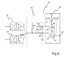
- FIG. 6 shows a further embodiment in which in a digital port anyway existing high-side switch and low-side switch as pull-up switch 44 and pull-down switch 46 are used.
- This embodiment is characterized in that the input circuit 43 then no separate pull-up switch and pull-down switch must have more, which reduces the number of components required and thus the space requirement of the input circuit and the costs incurred for the realization of the input circuit costs.
- Another advantage is that the embodiment of the FIG. 6 offers for the two resistors 26 and 36 of the embodiment of FIG. 5 by a single resistor 51 interposed between the input terminal 12 and a center tap 52 connected between the two in-line switches 44 and 46.
- FIGS. 6 and 7 are shown with the lying between the input terminal 12 and the microcomputer 24 circuit topologies each embodiments of a configurable by switching universal sensor input of a control unit 42, which can evaluate a single input circuit 43 in principle, both an analog signal and a PWM signal, and the is configured at the moment of installation of the control unit 42 in a motor vehicle or at an even later date suitable for each connected sensor type.
- a configuration here means an adaptation of the input impedance of the universal sensor input and a selection and activation of the software structures required for the evaluation of the sensor signals and adapted to the respective sensor type.
- the configuration can be programmed, for example, by end-of-line programming or else by autodetection of the connected sensor type carried out by control unit 42 within the scope of the zero-point programming required for the later operation of the connected sensor respectively.
- Zero point programming is understood to mean that the control unit 42 detects the value of the sensor signal in a defined state of the motor vehicle and stores it as a reference value, for example as a zero point.
- this zero-point programming is preceded by a sequence of steps with which the applied sensor signals are analyzed and with which the type of sensor installed in the respective vehicle type, or the number and types of built-in sensors is inferred, in order to obtain this information from there to use for the evaluation of the connected sensors.
- FIG. 7 shows a flowchart as an embodiment of such a method.
- step 54 the sequence of steps is started, wherein the start takes place in particular at the end of the tape, that is, after the installation of the control unit and the connection of the sensors, to input terminals 12 of the control unit 42.
- step 54 along with the start, the pull-down switch 46 is closed and the pull-up switch 44 is opened.
- the input impedance of the input circuit 43 of a control unit 42 as in connection with the Figures 5 and 6 has been adapted to an analog sensor 10.
- step 56 the microcomputer 24 then checks whether a constant DC voltage U is present at its input terminal 12, the value of which lies within a permitted range Uu ⁇ U ⁇ Uo.
- the lower limit Uu of the allowable range is, for example, two volts
- the upper limit Uo of the allowable range is, for example, three volts.
- step 58 it is stored that an analog sensor 10 is connected to the input terminal 12.
- adapted software structures are selected for the later evaluation of the sensor signals of the analog sensor 10.
- all software structures are preferably stored in the control unit 42, which are adapted for the evaluation of sensors to be connected potentially to the input terminal 12.
- step 56 this may mean that either no sensor is connected to the input terminal 12 or that a PWM sensor 34 is connected to the input terminal 12.
- the pull-down current path is deactivated by opening the pull-down switch 46 and the pull-up current path is activated by closing the pull-up switch 44. Thereby, the input impedance of the input circuit 43 is adjusted to a PWM sensor.
- the step sequence 60, 62, 64 can also be performed before the step sequence 54, 56, 58. It does not matter if you first check if a PWM sensor is connected or if an analog sensor is connected.
- step 62 it is checked in step 62 whether a signal with a frequency that is plausible for a PWM sensor 34 is present at the input terminal 12. This is done in one embodiment in that a frequency of the at the Input terminal 12 signal is compared with a lower frequency threshold fu and an upper frequency threshold fo. If the detected frequency is within the interval limited by the frequency thresholds fu and fo, the query in step 62 is answered in the affirmative and the program branches to step 64.
- step 64 it is stored that a PWM sensor 34 is connected to the input terminal 12, and for an evaluation of the signals of such a PWM sensor 34 adapted software structures for the later operation of the combination of this sensor type and the control unit 42nd selected.
- step 62 the program branches to a step 66 in which an error message is stored and / or signaled to an operator.
- the error message to be stored or displayed indicates that no functional sensor 10 or 34 is connected to the input terminal 12.
- the controller 42 has a plurality of configurable inputs, the auto-detection method of which an embodiment will be described with reference to FIGS FIG. 7 for each of the configurable sensor inputs. If neither an analog sensor 10 nor a PWM sensor 34 is detected at an input, the corresponding input is deactivated and not taken into account in the evaluation of the signal during later operation of the control unit.
- This constellation can occur, for example, when the individual vehicle requires only two sensors for a specific function, such as headlight range control, However, the control unit for this function offers three inputs to cover other vehicle variants.
- the configuration found, here the configuration with two sensors, an operator is signaled. Thus, errors of the sensors and / or the number of connected sensors can be detected at the end of the tape.
- control unit is also characterized in particular by the fact that it is set up to carry out the method presented here and / or one of its embodiments, wherein an embodiment is understood to mean the control of the method sequence.
Landscapes
- Physics & Mathematics (AREA)
- General Physics & Mathematics (AREA)
- Engineering & Computer Science (AREA)
- Automation & Control Theory (AREA)
- Analogue/Digital Conversion (AREA)
- Electronic Switches (AREA)
- Logic Circuits (AREA)
- Control By Computers (AREA)
Applications Claiming Priority (1)
| Application Number | Priority Date | Filing Date | Title |
|---|---|---|---|
| DE102010053304A DE102010053304B4 (de) | 2010-12-02 | 2010-12-02 | Steuergerät mit einem zur Verarbeitung von Signalen unterschiedlicher Sensortypen eingerichteten Eingang und Verfahren zum Anpassen eines Steuergeräts |
Publications (3)
| Publication Number | Publication Date |
|---|---|
| EP2461221A2 true EP2461221A2 (fr) | 2012-06-06 |
| EP2461221A3 EP2461221A3 (fr) | 2014-08-20 |
| EP2461221B1 EP2461221B1 (fr) | 2019-03-06 |
Family
ID=45217241
Family Applications (1)
| Application Number | Title | Priority Date | Filing Date |
|---|---|---|---|
| EP11189768.2A Active EP2461221B1 (fr) | 2010-12-02 | 2011-11-18 | Appareil de commande avec des entrées destinées au traitement de signaux provenant de types de capteurs différents |
Country Status (4)
| Country | Link |
|---|---|
| US (1) | US9122263B2 (fr) |
| EP (1) | EP2461221B1 (fr) |
| CN (1) | CN102540939A (fr) |
| DE (1) | DE102010053304B4 (fr) |
Cited By (7)
| Publication number | Priority date | Publication date | Assignee | Title |
|---|---|---|---|---|
| WO2015071321A1 (fr) * | 2013-11-13 | 2015-05-21 | Pilz Gmbh & Co. Kg | Commande de sécurité à entrées configurables |
| EP2905664A1 (fr) * | 2014-02-11 | 2015-08-12 | DORMA Deutschland GmbH | Actionneur de porte et son procédé d'assemblage |
| WO2015128336A1 (fr) * | 2014-02-26 | 2015-09-03 | Siemens Aktiengesellschaft | Circuit d'entrée à redondance, unité de circuit d'entrée comprenant au moins un circuit d'entrée et procédé servant à faire fonctionner une unité de circuit d'entrée de ce type |
| EP2966519A1 (fr) * | 2014-07-09 | 2016-01-13 | General Electric Company | Interface d'entrée/sortie universelle programmable |
| CN105320024A (zh) * | 2014-07-10 | 2016-02-10 | 通用电气公司 | 可编程通用io接口 |
| EP3229085A1 (fr) * | 2016-04-05 | 2017-10-11 | Siemens Aktiengesellschaft | Circuit d'entree destine a la detection selective d'un signal analogique ou binaire |
| EP3373085A1 (fr) * | 2017-03-11 | 2018-09-12 | Wilo Se | Ensemble circuit à entrée multifonction, en particulier pour l'unité électronique de commande et de régulation d'un groupe motopompe |
Families Citing this family (11)
| Publication number | Priority date | Publication date | Assignee | Title |
|---|---|---|---|---|
| US10704988B2 (en) * | 2013-02-28 | 2020-07-07 | Infineon Technologies Ag | Sensor systems and methods having emulated line adaptation |
| AU2017203621B1 (en) * | 2017-05-30 | 2018-07-26 | Victory Industrial Corporation | Control module for an alternator |
| DE102018208648A1 (de) * | 2018-05-30 | 2019-12-05 | Festo Ag & Co. Kg | Signalempfangseinrichtung, Steuereinrichtung und Verfahren |
| FR3090925B1 (fr) * | 2018-12-19 | 2021-03-19 | Continental Automotive France | Dispositif de détection automatique de couplage entre dispositifs électronique |
| DE102019106566B3 (de) * | 2019-03-14 | 2020-09-10 | Samson Aktiengesellschaft | Konfiguration eines zweipoligen Eingangs |
| FR3112872B1 (fr) | 2020-07-21 | 2022-07-22 | Vitesco Technologies | Dispositif de détection automatique de couplage entre dispositifs électroniques |
| FR3112870B1 (fr) * | 2020-07-21 | 2022-08-26 | Vitesco Technologies | Dispositif de détection automatique de couplage entre dispositifs électroniques |
| FR3112871B1 (fr) | 2020-07-21 | 2022-08-26 | Vitesco Technologies | Dispositif de détection automatique de couplage entre dispositifs électroniques |
| FR3112869B1 (fr) * | 2020-07-21 | 2022-06-24 | Vitesco Technologies | Dispositif de détection automatique de couplage entre dispositifs électroniques |
| DE102022127512B4 (de) | 2022-10-19 | 2025-06-26 | Audi Aktiengesellschaft | Steuerschaltung sowie Aktuatoreinheit mit einer Steuerschaltung und Verfahren zum Betreiben einer Steuerschaltung |
| DE102024107985A1 (de) * | 2024-03-20 | 2025-09-25 | Winterhalter Product & Technology GmbH | Flexible Eingangsschnittstelle zum Betrieb einer Spülmaschine |
Family Cites Families (5)
| Publication number | Priority date | Publication date | Assignee | Title |
|---|---|---|---|---|
| US4482822A (en) * | 1980-01-21 | 1984-11-13 | Sharp Kabushiki Kaisha | Semiconductor chip selection circuit having programmable level control circuitry using enhancement/depletion-mode MOS devices |
| US5982290A (en) * | 1998-09-10 | 1999-11-09 | New Holland North America, Inc. | Automatic recognition of different types of liquid level sensors |
| US7756812B2 (en) * | 2005-09-22 | 2010-07-13 | Eastman Kodak Company | Adaptive input-cell circuitry useful in configurable electronic controllers |
| US8140211B2 (en) * | 2008-01-22 | 2012-03-20 | GM Global Technology Operations LLC | Control module with flexible sensor inputs |
| US8326391B2 (en) * | 2008-03-12 | 2012-12-04 | General Electric Company | Sensor interface |
-
2010
- 2010-12-02 DE DE102010053304A patent/DE102010053304B4/de not_active Expired - Fee Related
-
2011
- 2011-11-18 EP EP11189768.2A patent/EP2461221B1/fr active Active
- 2011-11-30 US US13/307,297 patent/US9122263B2/en not_active Expired - Fee Related
- 2011-12-02 CN CN2011103968557A patent/CN102540939A/zh active Pending
Non-Patent Citations (1)
| Title |
|---|
| None |
Cited By (10)
| Publication number | Priority date | Publication date | Assignee | Title |
|---|---|---|---|---|
| WO2015071321A1 (fr) * | 2013-11-13 | 2015-05-21 | Pilz Gmbh & Co. Kg | Commande de sécurité à entrées configurables |
| US10558189B2 (en) | 2013-11-13 | 2020-02-11 | Pilz Gmbh & Co. Kg | Safety control system having configurable inputs |
| EP2905664A1 (fr) * | 2014-02-11 | 2015-08-12 | DORMA Deutschland GmbH | Actionneur de porte et son procédé d'assemblage |
| WO2015128336A1 (fr) * | 2014-02-26 | 2015-09-03 | Siemens Aktiengesellschaft | Circuit d'entrée à redondance, unité de circuit d'entrée comprenant au moins un circuit d'entrée et procédé servant à faire fonctionner une unité de circuit d'entrée de ce type |
| US10740272B2 (en) | 2014-02-26 | 2020-08-11 | Siemens Aktiengesellschaft | Input circuit that can be made redundant, input circuit unit having at least one input circuit, and method for operating the input circuit unit |
| EP2966519A1 (fr) * | 2014-07-09 | 2016-01-13 | General Electric Company | Interface d'entrée/sortie universelle programmable |
| CN105320024A (zh) * | 2014-07-10 | 2016-02-10 | 通用电气公司 | 可编程通用io接口 |
| CN105320024B (zh) * | 2014-07-10 | 2018-06-12 | 通用电气公司 | 可编程通用io接口 |
| EP3229085A1 (fr) * | 2016-04-05 | 2017-10-11 | Siemens Aktiengesellschaft | Circuit d'entree destine a la detection selective d'un signal analogique ou binaire |
| EP3373085A1 (fr) * | 2017-03-11 | 2018-09-12 | Wilo Se | Ensemble circuit à entrée multifonction, en particulier pour l'unité électronique de commande et de régulation d'un groupe motopompe |
Also Published As
| Publication number | Publication date |
|---|---|
| EP2461221A3 (fr) | 2014-08-20 |
| US9122263B2 (en) | 2015-09-01 |
| DE102010053304B4 (de) | 2012-08-02 |
| EP2461221B1 (fr) | 2019-03-06 |
| DE102010053304A1 (de) | 2012-06-06 |
| US20120139615A1 (en) | 2012-06-07 |
| CN102540939A (zh) | 2012-07-04 |
Similar Documents
| Publication | Publication Date | Title |
|---|---|---|
| EP2461221B1 (fr) | Appareil de commande avec des entrées destinées au traitement de signaux provenant de types de capteurs différents | |
| DE10147512B4 (de) | Verfahren zur Adressierung der Teilnehmer eines Bussystems | |
| EP3113984B1 (fr) | Appareil de commande pour système électrique multi-tension d'un véhicule automobile | |
| DE102013012615A1 (de) | Schaltungsmodul zum Trennen von Teilnetzen eines Mehrspannungsbordnetzes | |
| EP1732223B1 (fr) | Circuit intégré | |
| DE10330451B3 (de) | Vorrichtung zum Wecken eines Steuergerätes | |
| WO2025157348A1 (fr) | Procédé de fonctionnement d'une charge électrique dans un véhicule | |
| DE102018009221A1 (de) | DC-DC-Leistungswandler und Verfahren und Systeme zum Erfassen von Fehlermodi derselben | |
| DE19610992A1 (de) | Binärsensor | |
| DE102015206483A1 (de) | Schaltvorrichtung und Betriebsverfahren hierfür | |
| DE102017111544A1 (de) | Kombinierte PSI5- / DSI3-Datenschnittstelle für einen gemischten Verbau von Sensoren mit PSI5 und PSI3 Datenbusschnittstelle in Sensorsystemen | |
| DE102014103369B4 (de) | Ansteuerschaltung für einen Elektromotor | |
| DE102005061967B9 (de) | Leistungsversorgungsanordnung zum Bereitstellen eines Ausgangssignals mit einem vorbestimmten Ausgangssignalpegel | |
| DE10153846B4 (de) | Zünd- oder Einspritzmodul und zugehörendes Initialisierungsverfahren | |
| EP1298851A1 (fr) | Procédé d'adressage de noeuds d'un système de bus | |
| EP2503669B1 (fr) | Système d'automatisation de sécurite avec comportement de commutation contrôlé et avec dispositif d'accélération de commutation | |
| DE69708203T2 (de) | Halbleiteranordnung für Richtungsanzeigerblinkvorrichtung | |
| DE102020112985A1 (de) | IO-Link-Adapter | |
| DE102010028448A1 (de) | Schnittstellenschaltung und Verfahren zur Beeinflussung der Flankensteilheit eines Ansteuersignals | |
| DE19813952C1 (de) | Signalisierungsendstufe zur Erzeugung digitaler Spannungssignale auf einem Bussystem | |
| DE202004011221U1 (de) | Kraftfahrzeug-Lampensteuervorrichtung | |
| EP1898551B1 (fr) | Appareil comprenant un interface système | |
| DE10233978A1 (de) | Bussystem | |
| EP4275973B1 (fr) | Circuit d'alimentation électrique pour un actionneur d'une électrovanne, ensemble soupape pour un système de freinage d'un véhicule automobile et procédé d'alimentation en courant d'un actionneur d'électrovanne | |
| DE19715129C1 (de) | Schaltungsanordnung zur unabhängigen Ansteuerung zweier Verbraucher über eine Leitung |
Legal Events
| Date | Code | Title | Description |
|---|---|---|---|
| PUAI | Public reference made under article 153(3) epc to a published international application that has entered the european phase |
Free format text: ORIGINAL CODE: 0009012 |
|
| AK | Designated contracting states |
Kind code of ref document: A2 Designated state(s): AL AT BE BG CH CY CZ DE DK EE ES FI FR GB GR HR HU IE IS IT LI LT LU LV MC MK MT NL NO PL PT RO RS SE SI SK SM TR |
|
| AX | Request for extension of the european patent |
Extension state: BA ME |
|
| RIC1 | Information provided on ipc code assigned before grant |
Ipc: G05B 19/042 20060101AFI20140603BHEP |
|
| PUAL | Search report despatched |
Free format text: ORIGINAL CODE: 0009013 |
|
| AK | Designated contracting states |
Kind code of ref document: A3 Designated state(s): AL AT BE BG CH CY CZ DE DK EE ES FI FR GB GR HR HU IE IS IT LI LT LU LV MC MK MT NL NO PL PT RO RS SE SI SK SM TR |
|
| AX | Request for extension of the european patent |
Extension state: BA ME |
|
| RIC1 | Information provided on ipc code assigned before grant |
Ipc: G05B 19/042 20060101AFI20140715BHEP |
|
| 17P | Request for examination filed |
Effective date: 20150220 |
|
| RBV | Designated contracting states (corrected) |
Designated state(s): AL AT BE BG CH CY CZ DE DK EE ES FI FR GB GR HR HU IE IS IT LI LT LU LV MC MK MT NL NO PL PT RO RS SE SI SK SM TR |
|
| 17Q | First examination report despatched |
Effective date: 20160317 |
|
| STAA | Information on the status of an ep patent application or granted ep patent |
Free format text: STATUS: EXAMINATION IS IN PROGRESS |
|
| GRAP | Despatch of communication of intention to grant a patent |
Free format text: ORIGINAL CODE: EPIDOSNIGR1 |
|
| STAA | Information on the status of an ep patent application or granted ep patent |
Free format text: STATUS: GRANT OF PATENT IS INTENDED |
|
| INTG | Intention to grant announced |
Effective date: 20180418 |
|
| GRAJ | Information related to disapproval of communication of intention to grant by the applicant or resumption of examination proceedings by the epo deleted |
Free format text: ORIGINAL CODE: EPIDOSDIGR1 |
|
| STAA | Information on the status of an ep patent application or granted ep patent |
Free format text: STATUS: EXAMINATION IS IN PROGRESS |
|
| GRAP | Despatch of communication of intention to grant a patent |
Free format text: ORIGINAL CODE: EPIDOSNIGR1 |
|
| STAA | Information on the status of an ep patent application or granted ep patent |
Free format text: STATUS: GRANT OF PATENT IS INTENDED |
|
| INTC | Intention to grant announced (deleted) | ||
| INTG | Intention to grant announced |
Effective date: 20180913 |
|
| GRAS | Grant fee paid |
Free format text: ORIGINAL CODE: EPIDOSNIGR3 |
|
| GRAA | (expected) grant |
Free format text: ORIGINAL CODE: 0009210 |
|
| STAA | Information on the status of an ep patent application or granted ep patent |
Free format text: STATUS: THE PATENT HAS BEEN GRANTED |
|
| AK | Designated contracting states |
Kind code of ref document: B1 Designated state(s): AL AT BE BG CH CY CZ DE DK EE ES FI FR GB GR HR HU IE IS IT LI LT LU LV MC MK MT NL NO PL PT RO RS SE SI SK SM TR |
|
| REG | Reference to a national code |
Ref country code: GB Ref legal event code: FG4D Free format text: NOT ENGLISH |
|
| REG | Reference to a national code |
Ref country code: CH Ref legal event code: EP Ref country code: AT Ref legal event code: REF Ref document number: 1105371 Country of ref document: AT Kind code of ref document: T Effective date: 20190315 |
|
| REG | Reference to a national code |
Ref country code: DE Ref legal event code: R096 Ref document number: 502011015443 Country of ref document: DE |
|
| REG | Reference to a national code |
Ref country code: IE Ref legal event code: FG4D Free format text: LANGUAGE OF EP DOCUMENT: GERMAN |
|
| REG | Reference to a national code |
Ref country code: NL Ref legal event code: MP Effective date: 20190306 |
|
| REG | Reference to a national code |
Ref country code: LT Ref legal event code: MG4D |
|
| PG25 | Lapsed in a contracting state [announced via postgrant information from national office to epo] |
Ref country code: NO Free format text: LAPSE BECAUSE OF FAILURE TO SUBMIT A TRANSLATION OF THE DESCRIPTION OR TO PAY THE FEE WITHIN THE PRESCRIBED TIME-LIMIT Effective date: 20190606 Ref country code: FI Free format text: LAPSE BECAUSE OF FAILURE TO SUBMIT A TRANSLATION OF THE DESCRIPTION OR TO PAY THE FEE WITHIN THE PRESCRIBED TIME-LIMIT Effective date: 20190306 Ref country code: SE Free format text: LAPSE BECAUSE OF FAILURE TO SUBMIT A TRANSLATION OF THE DESCRIPTION OR TO PAY THE FEE WITHIN THE PRESCRIBED TIME-LIMIT Effective date: 20190306 Ref country code: LT Free format text: LAPSE BECAUSE OF FAILURE TO SUBMIT A TRANSLATION OF THE DESCRIPTION OR TO PAY THE FEE WITHIN THE PRESCRIBED TIME-LIMIT Effective date: 20190306 |
|
| PG25 | Lapsed in a contracting state [announced via postgrant information from national office to epo] |
Ref country code: RS Free format text: LAPSE BECAUSE OF FAILURE TO SUBMIT A TRANSLATION OF THE DESCRIPTION OR TO PAY THE FEE WITHIN THE PRESCRIBED TIME-LIMIT Effective date: 20190306 Ref country code: LV Free format text: LAPSE BECAUSE OF FAILURE TO SUBMIT A TRANSLATION OF THE DESCRIPTION OR TO PAY THE FEE WITHIN THE PRESCRIBED TIME-LIMIT Effective date: 20190306 Ref country code: HR Free format text: LAPSE BECAUSE OF FAILURE TO SUBMIT A TRANSLATION OF THE DESCRIPTION OR TO PAY THE FEE WITHIN THE PRESCRIBED TIME-LIMIT Effective date: 20190306 Ref country code: NL Free format text: LAPSE BECAUSE OF FAILURE TO SUBMIT A TRANSLATION OF THE DESCRIPTION OR TO PAY THE FEE WITHIN THE PRESCRIBED TIME-LIMIT Effective date: 20190306 Ref country code: GR Free format text: LAPSE BECAUSE OF FAILURE TO SUBMIT A TRANSLATION OF THE DESCRIPTION OR TO PAY THE FEE WITHIN THE PRESCRIBED TIME-LIMIT Effective date: 20190607 Ref country code: BG Free format text: LAPSE BECAUSE OF FAILURE TO SUBMIT A TRANSLATION OF THE DESCRIPTION OR TO PAY THE FEE WITHIN THE PRESCRIBED TIME-LIMIT Effective date: 20190606 |
|
| PG25 | Lapsed in a contracting state [announced via postgrant information from national office to epo] |
Ref country code: EE Free format text: LAPSE BECAUSE OF FAILURE TO SUBMIT A TRANSLATION OF THE DESCRIPTION OR TO PAY THE FEE WITHIN THE PRESCRIBED TIME-LIMIT Effective date: 20190306 Ref country code: IT Free format text: LAPSE BECAUSE OF FAILURE TO SUBMIT A TRANSLATION OF THE DESCRIPTION OR TO PAY THE FEE WITHIN THE PRESCRIBED TIME-LIMIT Effective date: 20190306 Ref country code: AL Free format text: LAPSE BECAUSE OF FAILURE TO SUBMIT A TRANSLATION OF THE DESCRIPTION OR TO PAY THE FEE WITHIN THE PRESCRIBED TIME-LIMIT Effective date: 20190306 Ref country code: PT Free format text: LAPSE BECAUSE OF FAILURE TO SUBMIT A TRANSLATION OF THE DESCRIPTION OR TO PAY THE FEE WITHIN THE PRESCRIBED TIME-LIMIT Effective date: 20190706 Ref country code: RO Free format text: LAPSE BECAUSE OF FAILURE TO SUBMIT A TRANSLATION OF THE DESCRIPTION OR TO PAY THE FEE WITHIN THE PRESCRIBED TIME-LIMIT Effective date: 20190306 Ref country code: CZ Free format text: LAPSE BECAUSE OF FAILURE TO SUBMIT A TRANSLATION OF THE DESCRIPTION OR TO PAY THE FEE WITHIN THE PRESCRIBED TIME-LIMIT Effective date: 20190306 Ref country code: SK Free format text: LAPSE BECAUSE OF FAILURE TO SUBMIT A TRANSLATION OF THE DESCRIPTION OR TO PAY THE FEE WITHIN THE PRESCRIBED TIME-LIMIT Effective date: 20190306 Ref country code: ES Free format text: LAPSE BECAUSE OF FAILURE TO SUBMIT A TRANSLATION OF THE DESCRIPTION OR TO PAY THE FEE WITHIN THE PRESCRIBED TIME-LIMIT Effective date: 20190306 |
|
| PG25 | Lapsed in a contracting state [announced via postgrant information from national office to epo] |
Ref country code: PL Free format text: LAPSE BECAUSE OF FAILURE TO SUBMIT A TRANSLATION OF THE DESCRIPTION OR TO PAY THE FEE WITHIN THE PRESCRIBED TIME-LIMIT Effective date: 20190306 Ref country code: SM Free format text: LAPSE BECAUSE OF FAILURE TO SUBMIT A TRANSLATION OF THE DESCRIPTION OR TO PAY THE FEE WITHIN THE PRESCRIBED TIME-LIMIT Effective date: 20190306 |
|
| REG | Reference to a national code |
Ref country code: DE Ref legal event code: R097 Ref document number: 502011015443 Country of ref document: DE |
|
| PG25 | Lapsed in a contracting state [announced via postgrant information from national office to epo] |
Ref country code: IS Free format text: LAPSE BECAUSE OF FAILURE TO SUBMIT A TRANSLATION OF THE DESCRIPTION OR TO PAY THE FEE WITHIN THE PRESCRIBED TIME-LIMIT Effective date: 20190706 |
|
| PLBE | No opposition filed within time limit |
Free format text: ORIGINAL CODE: 0009261 |
|
| STAA | Information on the status of an ep patent application or granted ep patent |
Free format text: STATUS: NO OPPOSITION FILED WITHIN TIME LIMIT |
|
| PG25 | Lapsed in a contracting state [announced via postgrant information from national office to epo] |
Ref country code: DK Free format text: LAPSE BECAUSE OF FAILURE TO SUBMIT A TRANSLATION OF THE DESCRIPTION OR TO PAY THE FEE WITHIN THE PRESCRIBED TIME-LIMIT Effective date: 20190306 |
|
| 26N | No opposition filed |
Effective date: 20191209 |
|
| PG25 | Lapsed in a contracting state [announced via postgrant information from national office to epo] |
Ref country code: SI Free format text: LAPSE BECAUSE OF FAILURE TO SUBMIT A TRANSLATION OF THE DESCRIPTION OR TO PAY THE FEE WITHIN THE PRESCRIBED TIME-LIMIT Effective date: 20190306 |
|
| PG25 | Lapsed in a contracting state [announced via postgrant information from national office to epo] |
Ref country code: TR Free format text: LAPSE BECAUSE OF FAILURE TO SUBMIT A TRANSLATION OF THE DESCRIPTION OR TO PAY THE FEE WITHIN THE PRESCRIBED TIME-LIMIT Effective date: 20190306 |
|
| REG | Reference to a national code |
Ref country code: CH Ref legal event code: PL |
|
| PG25 | Lapsed in a contracting state [announced via postgrant information from national office to epo] |
Ref country code: CH Free format text: LAPSE BECAUSE OF NON-PAYMENT OF DUE FEES Effective date: 20191130 Ref country code: LI Free format text: LAPSE BECAUSE OF NON-PAYMENT OF DUE FEES Effective date: 20191130 Ref country code: MC Free format text: LAPSE BECAUSE OF FAILURE TO SUBMIT A TRANSLATION OF THE DESCRIPTION OR TO PAY THE FEE WITHIN THE PRESCRIBED TIME-LIMIT Effective date: 20190306 Ref country code: LU Free format text: LAPSE BECAUSE OF NON-PAYMENT OF DUE FEES Effective date: 20191118 |
|
| REG | Reference to a national code |
Ref country code: BE Ref legal event code: MM Effective date: 20191130 |
|
| GBPC | Gb: european patent ceased through non-payment of renewal fee |
Effective date: 20191118 |
|
| PG25 | Lapsed in a contracting state [announced via postgrant information from national office to epo] |
Ref country code: IE Free format text: LAPSE BECAUSE OF NON-PAYMENT OF DUE FEES Effective date: 20191118 Ref country code: FR Free format text: LAPSE BECAUSE OF NON-PAYMENT OF DUE FEES Effective date: 20191130 Ref country code: GB Free format text: LAPSE BECAUSE OF NON-PAYMENT OF DUE FEES Effective date: 20191118 |
|
| PG25 | Lapsed in a contracting state [announced via postgrant information from national office to epo] |
Ref country code: BE Free format text: LAPSE BECAUSE OF NON-PAYMENT OF DUE FEES Effective date: 20191130 |
|
| REG | Reference to a national code |
Ref country code: AT Ref legal event code: MM01 Ref document number: 1105371 Country of ref document: AT Kind code of ref document: T Effective date: 20191118 |
|
| PG25 | Lapsed in a contracting state [announced via postgrant information from national office to epo] |
Ref country code: AT Free format text: LAPSE BECAUSE OF NON-PAYMENT OF DUE FEES Effective date: 20191118 |
|
| PG25 | Lapsed in a contracting state [announced via postgrant information from national office to epo] |
Ref country code: CY Free format text: LAPSE BECAUSE OF FAILURE TO SUBMIT A TRANSLATION OF THE DESCRIPTION OR TO PAY THE FEE WITHIN THE PRESCRIBED TIME-LIMIT Effective date: 20190306 |
|
| PG25 | Lapsed in a contracting state [announced via postgrant information from national office to epo] |
Ref country code: MT Free format text: LAPSE BECAUSE OF FAILURE TO SUBMIT A TRANSLATION OF THE DESCRIPTION OR TO PAY THE FEE WITHIN THE PRESCRIBED TIME-LIMIT Effective date: 20190306 Ref country code: HU Free format text: LAPSE BECAUSE OF FAILURE TO SUBMIT A TRANSLATION OF THE DESCRIPTION OR TO PAY THE FEE WITHIN THE PRESCRIBED TIME-LIMIT; INVALID AB INITIO Effective date: 20111118 |
|
| PG25 | Lapsed in a contracting state [announced via postgrant information from national office to epo] |
Ref country code: MK Free format text: LAPSE BECAUSE OF FAILURE TO SUBMIT A TRANSLATION OF THE DESCRIPTION OR TO PAY THE FEE WITHIN THE PRESCRIBED TIME-LIMIT Effective date: 20190306 |
|
| REG | Reference to a national code |
Ref country code: DE Ref legal event code: R084 Ref document number: 502011015443 Country of ref document: DE |
|
| PGFP | Annual fee paid to national office [announced via postgrant information from national office to epo] |
Ref country code: DE Payment date: 20251022 Year of fee payment: 15 |
|
| REG | Reference to a national code |
Ref country code: DE Ref legal event code: R081 Ref document number: 502011015443 Country of ref document: DE Owner name: MARELLI GERMANY GMBH, DE Free format text: FORMER OWNER: AUTOMOTIVE LIGHTING REUTLINGEN GMBH, 72762 REUTLINGEN, DE |