EP2461345B1 - Appareil de commutation électrique configurable incluant plusieurs contacts séparables et plusieurs bretelles configurables de champ pour fournir plusieurs pôles - Google Patents
Appareil de commutation électrique configurable incluant plusieurs contacts séparables et plusieurs bretelles configurables de champ pour fournir plusieurs pôles Download PDFInfo
- Publication number
- EP2461345B1 EP2461345B1 EP11009554.4A EP11009554A EP2461345B1 EP 2461345 B1 EP2461345 B1 EP 2461345B1 EP 11009554 A EP11009554 A EP 11009554A EP 2461345 B1 EP2461345 B1 EP 2461345B1
- Authority
- EP
- European Patent Office
- Prior art keywords
- terminals
- field
- separable contacts
- switching apparatus
- pairs
- Prior art date
- Legal status (The legal status is an assumption and is not a legal conclusion. Google has not performed a legal analysis and makes no representation as to the accuracy of the status listed.)
- Active
Links
Images




Classifications
-
- H—ELECTRICITY
- H01—ELECTRIC ELEMENTS
- H01H—ELECTRIC SWITCHES; RELAYS; SELECTORS; EMERGENCY PROTECTIVE DEVICES
- H01H71/00—Details of the protective switches or relays covered by groups H01H73/00 - H01H83/00
- H01H71/08—Terminals; Connections
-
- H—ELECTRICITY
- H01—ELECTRIC ELEMENTS
- H01H—ELECTRIC SWITCHES; RELAYS; SELECTORS; EMERGENCY PROTECTIVE DEVICES
- H01H11/00—Apparatus or processes specially adapted for the manufacture of electric switches
- H01H11/0006—Apparatus or processes specially adapted for the manufacture of electric switches for converting electric switches
- H01H11/0031—Apparatus or processes specially adapted for the manufacture of electric switches for converting electric switches for allowing different types or orientation of connections to contacts
-
- H—ELECTRICITY
- H01—ELECTRIC ELEMENTS
- H01H—ELECTRIC SWITCHES; RELAYS; SELECTORS; EMERGENCY PROTECTIVE DEVICES
- H01H71/00—Details of the protective switches or relays covered by groups H01H73/00 - H01H83/00
- H01H71/08—Terminals; Connections
- H01H71/082—Connections between juxtaposed circuit breakers
-
- H—ELECTRICITY
- H01—ELECTRIC ELEMENTS
- H01H—ELECTRIC SWITCHES; RELAYS; SELECTORS; EMERGENCY PROTECTIVE DEVICES
- H01H71/00—Details of the protective switches or relays covered by groups H01H73/00 - H01H83/00
- H01H71/10—Operating or release mechanisms
- H01H71/1045—Multiple circuits-breaker, e.g. for the purpose of dividing current or potential drop
-
- H—ELECTRICITY
- H01—ELECTRIC ELEMENTS
- H01R—ELECTRICALLY-CONDUCTIVE CONNECTIONS; STRUCTURAL ASSOCIATIONS OF A PLURALITY OF MUTUALLY-INSULATED ELECTRICAL CONNECTING ELEMENTS; COUPLING DEVICES; CURRENT COLLECTORS
- H01R31/00—Coupling parts supported only by co-operation with counterpart
- H01R31/08—Short-circuiting members for bridging contacts in a counterpart
Definitions
- the disclosed concept pertains generally to electrical switching apparatus and, more particularly, to circuit breakers including a plurality of separable contacts.
- U.S. Patent No. 6,614,334 discloses a series arrangement of two circuit breaker mechanisms.
- the interruption performance of the circuit breaker is determined by the "current limitation of series arcs," which provides two arcs in series, thereby having twice the resistance of a single arc.
- Circuit breakers are typically available in one-, two-, three- and four-pole construction, although larger counts of poles are possible.
- FR 2 427 679 A1 relates to a multi-pole circuit breaker for a low voltage distribution network formed by an assembly of single-pole modules of identical structures each comprising stacked insulating gear for housing a pair of stationary and movable contacts, an operating mechanism and a thermal tripping device.
- An electromagnetic coupling tongue is fitted over respective levers of the modules, and a common trigger cooperates with the triggers of all modules.
- a comb formed by connecting conductors provides coupling of at least two modules in series, and is arranged along one edge of the assembly.
- EP 2 189 996 A1 relates to a circuit breaker device for bidirectional direct current and an installation with photovoltaic cells provided with such a device.
- the device has a predefined even number of separable contacts comprising two contacts electrically connected to connection terminals.
- Arc chutes are provided with respective arc formation chambers.
- Tripping mechanisms are associated with respective pairs of separable contacts to separate the separable contacts of the pairs in response to electric faults in an electric line. The tripping mechanisms are connected to each other by a mechanical link permitting simultaneous opening of separable contacts.
- circuit breakers including a plurality of separable contacts.
- an electrical switching apparatus as set forth in claim 1 is provided. Further embodiments are claimed in the dependent claims. These needs and others are met by embodiments of the disclosed concept, in which the electrical switching apparatus inter alia comprises: at least one pole; a plurality of first terminals; a plurality of second terminals; a plurality of pairs of separable contacts; and a plurality of field-configurable jumpers, each of the plurality of field-configurable jumpers electrically connecting two of the pairs of separable contacts in series, each of the plurality of field-configurable jumpers being electrically connected to: (a) two of the first terminals, (b) two of the first terminals or two of the second terminals; or (c) one of the first terminals and one of the second terminals.
- N may be an integer count of the at least one pole; the N of the plurality of first terminals may be input terminals; the N of the plurality of second terminals may be output terminals; two of the pairs of separable contacts may be electrically connected in series for each of the at least one pole; and each of the N of the plurality of field-configurable jumpers may be electrically connected between one of the plurality of first terminals that may be not one of the input terminals and one of the plurality of second terminals that may be not one of the output terminals.
- the at least one pole may be the integer count N of a plurality of poles structured to power an AC load having the integer count N of a plurality of phases.
- Each of the plurality of field-configurable jumpers may be electrically connected to the one of the first terminals and the one of the second terminals.
- N may be an integer count of the at least one pole; the N of the plurality of second terminals may be input terminals; the N of the plurality of second terminals may be output terminals; two of the pairs of separable contacts may be electrically connected in series for each of the at least one pole; and each of the N of the plurality of field-configurable jumpers may be electrically connected between two of the plurality of first terminals.
- Each of the plurality of field-configurable jumpers may be electrically connected to the two of the first terminals.
- Two of the plurality of first terminals may be input terminals; two of the plurality of second terminals may be output terminals; N may be an integer count of the plurality of field-configurable jumpers; two of the pairs of separable contacts may be electrically connected to the output terminals; half of the N field-configurable jumpers may electrically connect half of the pairs of separable contacts in series between one of the input terminals and one of the output terminals; the other half of the N field-configurable jumpers may electrically connect the other half of the pairs of separable contacts in series between the other one of the input terminals and the other one of the output terminals; and the output terminals may be structured for electrical connection to a load.
- One of the plurality of first terminals may be an input terminal; another one of the plurality of first terminals may be an output terminal; N may be an integer count of the plurality of field-configurable jumpers; one of the pairs of separable contacts may be electrically connected to the input terminal; another one of the pairs of separable contacts may be electrically connected to the output terminal; the N of the plurality of field-configurable jumpers may electrically connect the pairs of separable contacts in series between the input terminal and the output terminal; and the input terminal and the output terminal may be structured to receive the series combination of a load and a power source.
- Each of the plurality of field-configurable jumpers may be electrically connected to the two of the first terminals or two of the second terminals.
- number shall mean one or an integer greater than one ( i.e., a plurality).
- fastener shall mean screws, bolts and the combinations of bolts and nuts (e.g. , without limitation, lock nuts) and bolts, washers and nuts.
- electrical conductor shall mean a wire (e.g., solid; stranded; insulated; non-insulated), a copper conductor, an aluminum conductor, a suitable metal conductor, or other suitable material or object that permits an electric current to flow easily.
- low voltage shall mean a voltage less than or equal to about 1000 VAC or about 750 VDC.
- high voltage for a low voltage device shall mean greater than a “low voltage” and up to approximately 1500 volts, although this may be slightly higher depending upon the application but no more than 2000 volts.
- the disclosed concept is described in association with six-pole circuit breakers (i.e., having six pairs of separable contacts), although the disclosed concept is applicable to a wide range of electrical switching apparatus having eight poles (i.e., having eight pairs of separable contacts) or any other suitable plurality of poles.
- An example six-pole air circuit breaker as disclosed herein can include terminals accessible for every pole for both high voltage (for a low voltage device) AC and DC applications. With accessibility to terminals of each pole, the six-pole circuit breaker can be wired or otherwise configured in different ways. For example, with six poles electrically connected in series, it can be used for applications with systems voltages over 600 VDC. With two poles tied in series, for instance, it can be used for three-phase applications over 600 VAC.
- the system ground could be either at the power end or at the load (at the site).
- the disclosed concept can be employed, for example and without limitation, for "green” systems (e.g., wind and solar segments).
- configured electrical switching apparatus such as circuit breakers 100,200,300,400, include at least one pole.
- three configured poles 102,202 are shown in respective Figures 1 and 2
- one configured pole 302,402 is shown in Figures 3 and 4 , respectively.
- the circuit breakers 100,200,300,400 further include a plurality of first terminals 104,204,304,404, a plurality of second terminals 106,206,306,406, a plurality of pairs of separable contacts 108,208,308,408, and a plurality of field-configurable jumpers 110,210,310,410, respectively.
- Each of the plurality of field-configurable jumpers 110,210,310,410 electrically connects two of the respective pairs of separable contacts 108,208,308,408 in series.
- Each of the plurality of field-configurable jumpers 110,210,310,410 is electrically connected to: (a) two of the first terminals 204 as shown with the jumpers 210 in Figure 2 , (b) two of the first terminals 304,404 or two of the second terminals 306,406 as shown with the jumpers 310,410 in Figures 3 and 4 , respectively, or (c) one of the first terminals 104 and one of the second terminals 106 as shown with the jumpers 110 in Figure 1 .
- example circuit breakers 100,200,300,400 can be the same or similar devices except for the specific example configurations of the various field-configurable jumpers 110,210,310,410.
- N of the plurality of first terminals 104 are input terminals.
- N of the plurality of second terminals 106 are output terminals.
- Two of the pairs of separable contacts 108 are electrically connected in series for each of the three example poles 102.
- Each of N of the plurality of field-configurable jumpers 110 is electrically connected between one of the plurality of first terminals 104 that is not one of the input terminals and one of the plurality of second terminals 106 that is not one of the output terminals.
- the circuit breaker 100 can input three input phases 112 (as shown in phantom line drawing) (e.g., without limitation, phases A, B and C from an example three-phase power source (not shown)) and output three output phases 114 (as shown in phantom line drawing) (e.g., without limitation, phases A, B and C to an example three-phase load (not shown)).
- input phases 112 as shown in phantom line drawing
- output phases 114 as shown in phantom line drawing
- the three example poles 102 are structured to power an AC load (not shown) having three example phases. It will be appreciated, however, that any suitable number of phases can be employed for either AC or DC loads.
- N of the plurality of second terminals 206 are input terminals.
- N of the plurality of second terminals 206 are output terminals.
- Two of the pairs of separable contacts 208 are electrically connected in series for each of the three example poles 202.
- Each of N of the field-configurable jumpers 210 is electrically connected between two of the plurality of first terminals 204.
- the circuit breaker 200 can input three input phases 212 (as shown in phantom line drawing) (from an example three-phase power source (not shown)) and output three output phases 214 (as shown in phantom line drawing) (to an example three-phase load (not shown)).
- the three example poles 202 are structured to power an AC load (not shown) having three example phases. It will be appreciated, however, that any suitable number of phases can be employed for either AC or DC loads.
- two of the plurality of first terminals 304 are input terminals
- two of the plurality of second terminals 306 are output terminals for a load 312 (shown in phantom line drawing)
- two of the pairs of separable contacts 308 are electrically connected to the output terminals for the load 312
- the other half of the N field-configurable jumpers 310 electrically connect the other half of the pairs of separable contacts 308 in series between the other one of the input terminals 304 and the other one of the output terminals for the load 312.
- the example load 312 is a DC load
- the example pole 302 is structured to power the DC load.
- the circuit breaker 300 as configured in Figure 3 , can input one DC input 314 (as shown in phantom line drawing) (from an example DC power source (not shown)) and output one DC output 316 (as shown in phantom line drawing) to the example DC load 312.
- one of the plurality of first terminals 404 is an input terminal
- another one of the plurality of first terminals 404 is an output terminal
- one of the pairs of separable contacts 408 is electrically connected to the input terminal
- another one of the pairs of separable contacts 408 is electrically connected to the output terminal
- N of the plurality of field-configurable jumpers 410 electrically connect the pairs of separable contacts 408 in series between the input terminal and the output terminal
- the input terminal and the output terminal are structured to receive the series combination of a load 412 and a power source 414.
- the example load 412 is a DC load, and the pole 402 is structured to power the DC load.
- the circuit breaker 400 as configured in Figure 4 , can input one DC input from the DC power source 414 (as shown in phantom line drawing) for the DC load 412.
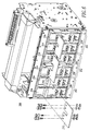
- Figures 5-8 shows the respective circuit breakers 100,200,300,400. It will be appreciated that the separable contacts 108,208,308,408 of Figures 1-4 , respectively, are not shown along with the corresponding circuit breaker operating mechanism (not shown) and trip unit (not shown).
- each of the field-configurable jumpers 110 is an electrical conductor including a first planar portion 116, a second planar portion 118 and a third planar portion 120.
- the first planar portion 116 is parallel to the third planar portion 120.
- the second planar portion 118 is normal to the first planar portion 116 and to the third planar portion 120.
- the first planar portion 116 is electrically connected to one of the first terminals 104 by a number of fasteners 122.
- the third planar portion 120 is electrically connected to one of the second terminals 106 by a number of fasteners 124.
- the example second planar portion 118 is a non-rectangular parallelogram, in order to accommodate the width offset and the height offset between the corresponding terminals 104,106.
- each of the field-configurable jumpers 210,310,410 is a planar U-shaped electrical conductor.
Landscapes
- Engineering & Computer Science (AREA)
- Manufacturing & Machinery (AREA)
- Breakers (AREA)
- Keying Circuit Devices (AREA)
- Rotary Switch, Piano Key Switch, And Lever Switch (AREA)
Claims (15)
- Appareil de commutation électrique (100 ; 200 ; 300 ; 400) comprenant .au moins un pôle (102 ; 202 ; 302 ; 402) ;une pluralité de premières bornes (104, 204 ; 304 ; 404) ;une pluralité de deuxièmes bornes (106 ; 206 ; 306 ; 406) ;une pluralité de paires de contacts séparables (108 ; 208 ; 308 ; 408) ; etune pluralité de cavaliers configurables sur site (110 ; 210 ; 310 ; 410), chaque cavalier de la pluralité de cavaliers configurables sur site connectant deux des paires de contacts séparables en série, chaque cavalier de la pluralité de cavaliers configurables sur site étant connecté électriquement à : (a) deux des premières bornes (204), (b) deux des premières bornes (304 ; 404) ou deux des deuxièmes bornes (306 ; 406) ; ou (c) l'une des premières bornes (104) et l'une des deuxièmes bornes (106),caractérisé en ce que les premières bornes (104 ; 204 ; 304 ; 404) sont disposées au-dessus des deuxièmes bornes (106 ; 206 ; 306 ; 406), eten ce que la totalité des premières bornes (104 ; 204 ; 304 ; 404), des deuxièmes bornes (106 ; 206 ; 306 ; 406) et des cavaliers configurables sur site (110 ; 210 ; 310 ; 410) sont accessibles à partir d'un côté de l'appareil de commutation électrique (100 ; 200 ; 300 ; 400).
- Appareil de commutation électrique (100) selon la revendication 1, dans lequel N est un compte entier desdits au moins un pôle (102) ; dans lequel les N bornes de la pluralité de premières bornes sont des bornes d'entrée (104) ; dans lequel les N bornes de la pluralité de deuxièmes bornes sont des bornes de sortie (106) ; dans lequel deux des paires de contacts séparables (108) sont connectées électriquement en série pour chacun desdits au moins un pôle ; et dans lequel chacun des N cavaliers de la pluralité de cavaliers configurables sur site (110) est connecté électriquement entre l'une de la pluralité de premières bornes qui n'est pas l'une des bornes d'entrée et l'une de la pluralité de deuxièmes bornes qui n'est pas l'une des bornes de sortie.
- Appareil de commutation électrique (100) selon revendication 1, dans lequel N est un compte entier desdits au moins un pôle ; dans lequel les N bornes de la pluralité de deuxièmes bornes sont des bornes d'entrée ; dans lequel les N bornes de la pluralité de deuxièmes bornes sont des bornes de sortie ; dans lequel deux des paires de contacts séparables sont connectés électriquement en série pour chacun desdits au moins un pôle ; et dans lequel chacun des N cavaliers de la pluralité de cavaliers configurables sur site est connecté électriquement entre deux bornes de la pluralité de premières bornes.
- Appareil de commutation électrique (300) selon la revendication 1, dans lequel deux bornes de la pluralité de premières bornes sont des bornes d'entrée (304) ; dans lequel deux bornes de la pluralité de deuxièmes bornes sont des bornes de sortie (306) ; dans lequel N est un compte entier de la pluralité de cavaliers configurables sur site (310) ; dans lequel deux des paires de contacts séparables (308) sont connectées électriquement aux bornes de sortie ; dans lequel la moitié des N cavaliers configurables sur site connectent électriquement la moitié des paires de contacts séparables en série entre l'une des bornes d'entrée et l'une des bornes de sortie ; dans lequel l'autre moitié des N cavaliers configurables sur site connectent électriquement l'autre moitié des paires de contacts séparables en série entre l'autre des bornes d'entrée et l'autre des bornes de sortie ; et dans lequel les bornes de sortie sont agencées pour une connexion électrique à une charge (312).
- Appareil de commutation électrique (400) selon la revendication 1, dans lequel l'une de la pluralité de premières bornes est une borne d'entrée (404) ; dans lequel une autre de la pluralité de premières bornes est une borne de sortie (404) ; dans lequel N est un compte entier de la pluralité de cavaliers configurables sur site (410) ; dans lequel l'une des paires de contacts séparables (408) est connectée électriquement à la borne d'entrée ; dans lequel une autre des paires de contacts séparables est connectée électriquement à la borne de sortie ; dans lequel N cavaliers de la pluralité de cavaliers configurables sur site connectent électriquement les paires de contacts séparables en série entre la borne d'entrée et la borne de sortie ; et dans lequel la borne d'entrée et la borne de sortie sont agencées pour recevoir la combinaison en série d'une charge (412) et d'une source d'alimentation (414).
- Appareil de commutation électrique (300 ; 400) selon les revendications 4 ou 5, dans lequel la charge est une charge DC (312 ; 412) ; et dans lequel ledit au moins un pôle est un pôle (302 ; 402) agencé pour alimenter la charge DC.
- Appareil de commutation électrique (200) selon la revendication 1, dans lequel chaque cavalier de la pluralité de cavaliers configurables sur site (210) est connecté électriquement auxdites deux des premières bornes (204).
- Appareil de commutation électrique (200) selon la revendication 7, dans lequel ledit au moins un pôle est constitué d'une pluralité de pôles (202) agencés pour alimenter une charge AC ayant une pluralité de phase.
- Appareil de commutation électrique (300 ; 400) selon la revendication 1, dans lequel chaque cavalier de la pluralité de cavaliers configurables sur site (310 ; 410) est connecté électriquement auxdites deux des premières bornes (304 ; 404) ou auxdites deux des deuxièmes bornes (306 ; 406).
- Appareil de commutation électrique (300 ; 400) selon la revendication 9, dans lequel ledit au moins un pôle est un pôle (302 ; 402) agencé pour alimenter une charge DC (312 ; 412).
- Appareil de commutation électrique (300 ; 400) selon la revendication 10, dans lequel la pluralité de premières bornes est constituée de six premières bornes (304 ; 404) ; dans lequel la pluralité de deuxièmes bornes est constituée de six deuxièmes bornes (306 ; 406) ; dans lequel la pluralité de paires de contacts séparables est constituée de six paires de contacts séparables (308 ; 408) ; et dans lequel la pluralité de cavaliers configurables sur site est constituée de quatre ou cinq cavaliers configurables sur site (310 ; 410).
- Appareil de commutation électrique (100) selon la revendication 1, dans lequel chaque cavalier de la pluralité de cavaliers configurables sur site (110) est connecté électriquement à ladite une des premières bornes (104) et à ladite une des deuxièmes bornes (66).
- Appareil de commutation électrique (100) selon la revendication 12, dans lequel ledit au moins un pôle est constitué d'une pluralité de pôles (102) agencés pour alimenter une charge AC ayant une pluralité de phase.
- Appareil de commutation électrique selon la revendication 1, dans lequel chaque cavalier de la pluralité de cavaliers configurables sur site est un conducteur électrique en forme de U (210 ; 310 ; 410).
- Appareil de commutation électrique selon la revendication 1, dans lequel chaque cavalier de la pluralité de cavaliers configurables sur site est un conducteur électrique (110) comprenant une première portion plane (116), une deuxième portion plane (118) et une troisième portion plane (120) ; dans lequel la première portion plane est parallèle à la troisième portion plane ; dans lequel la deuxième portion plane est normale à la première portion plane et à la troisième portion plane ; dans lequel la première portion plane est connectée électriquement à ladite une des premières bornes ; dans lequel la troisième portion plane est connectée électriquement à ladite une des deuxièmes bornes ; et dans lequel la deuxième portion plane est un parallélogramme non rectangulaire.
Applications Claiming Priority (1)
| Application Number | Priority Date | Filing Date | Title |
|---|---|---|---|
| US12/958,566 US8253044B2 (en) | 2010-12-02 | 2010-12-02 | Configurable electrical switching apparatus including a plurality of separable contacts and a plurality of field-configurable jumpers to provide a number of poles |
Publications (3)
| Publication Number | Publication Date |
|---|---|
| EP2461345A2 EP2461345A2 (fr) | 2012-06-06 |
| EP2461345A3 EP2461345A3 (fr) | 2012-10-17 |
| EP2461345B1 true EP2461345B1 (fr) | 2016-05-18 |
Family
ID=46161187
Family Applications (1)
| Application Number | Title | Priority Date | Filing Date |
|---|---|---|---|
| EP11009554.4A Active EP2461345B1 (fr) | 2010-12-02 | 2011-12-02 | Appareil de commutation électrique configurable incluant plusieurs contacts séparables et plusieurs bretelles configurables de champ pour fournir plusieurs pôles |
Country Status (4)
| Country | Link |
|---|---|
| US (1) | US8253044B2 (fr) |
| EP (1) | EP2461345B1 (fr) |
| AU (1) | AU2011253735B2 (fr) |
| CA (1) | CA2760372A1 (fr) |
Cited By (1)
| Publication number | Priority date | Publication date | Assignee | Title |
|---|---|---|---|---|
| CN108389761A (zh) * | 2018-02-13 | 2018-08-10 | 乐志胜 | 一种用于紧凑型接地电路的断路器 |
Families Citing this family (11)
| Publication number | Priority date | Publication date | Assignee | Title |
|---|---|---|---|---|
| US9025298B2 (en) | 2012-10-22 | 2015-05-05 | Eaton Corporation | Electrical switching apparatus including transductor circuit and alternating current electronic trip circuit |
| US9384928B2 (en) * | 2012-10-22 | 2016-07-05 | Eaton Coporation | Electrical switching apparatus including transductor circuit and alternating current electronic trip circuit |
| US9368306B2 (en) | 2013-02-07 | 2016-06-14 | Abl Ip Holding Llc | Configurable multi-pole relay |
| WO2015088654A1 (fr) * | 2013-12-09 | 2015-06-18 | Eaton Corporation | Appareil de commutation électrique comprenant un circuit de transducteur et un circuit de déclenchement électronique à courant alternatif |
| EP3084799B1 (fr) * | 2013-12-18 | 2017-12-20 | Eaton Corporation | Appareil de commutation électrique comprenant un circuit de déclenchement électronique en courant alternatif à circuit de détection de défaut d'arc |
| US9466968B2 (en) * | 2013-12-18 | 2016-10-11 | Eaton Corporation | Electrical switching apparatus including alternating current electronic trip circuit with arc fault detection circuit and power supply |
| US10923305B2 (en) * | 2016-07-13 | 2021-02-16 | Mitsubishi Electric Corporation | No-voltage output and voltage output switching circuit |
| KR101823516B1 (ko) | 2016-08-31 | 2018-01-30 | 엘에스산전 주식회사 | 직류 배선용 차단기의 트립 장치 |
| KR20180094413A (ko) | 2017-02-15 | 2018-08-23 | 엘에스산전 주식회사 | 직류 배선용 차단기 |
| KR102108146B1 (ko) * | 2017-12-27 | 2020-05-11 | 엘에스일렉트릭(주) | 직류 차단기 |
| CN112787124B (zh) * | 2019-11-11 | 2024-02-06 | 北京京人电器有限公司 | 一种电连接机构 |
Family Cites Families (13)
| Publication number | Priority date | Publication date | Assignee | Title |
|---|---|---|---|---|
| DE1959962U (de) * | 1967-01-24 | 1967-05-11 | Elektrotechnische Fabrik Kuepp | Schaltgeraetebank mit kontaktbruecken. |
| US3909097A (en) * | 1974-08-06 | 1975-09-30 | Intertherm | Bus bar terminal means for pairs of circuit-braking elements |
| FR2427679A1 (fr) * | 1978-05-29 | 1979-12-28 | Merlin Gerin | Disjoncteur multipolaire a peigne de connexion de modules en serie |
| US4222088A (en) * | 1978-09-27 | 1980-09-09 | Burton Richard H | Electronic lock |
| US4947068A (en) * | 1989-03-30 | 1990-08-07 | Emerson Electric Co. | Motor for whirlpool baths |
| US5504689A (en) * | 1993-12-16 | 1996-04-02 | Dell Usa, L.P. | Apparatus and method for testing computer bus characteristics |
| US5726507A (en) * | 1996-01-19 | 1998-03-10 | Basic Resources, Inc. | Temporary electrical interfaces, install ations, processes, and systems for contruction sites |
| DE19718231C1 (de) * | 1997-04-30 | 1998-09-24 | Harting Kgaa | Schalterstecker |
| US20030148658A1 (en) * | 2002-02-04 | 2003-08-07 | Lias Edward Ethber | Circuit breaker jumper assembly with cover assembly access knockouts |
| US6614334B1 (en) | 2002-06-27 | 2003-09-02 | Eaton Corporation | Circuit breaker including two circuit breaker mechanisms and an operating handle |
| US20050073789A1 (en) * | 2003-08-28 | 2005-04-07 | James Tanis | Solid state multi-pole switching device for plug-in switching units |
| FR2938969A1 (fr) * | 2008-11-21 | 2010-05-28 | Schneider Electric Ind Sas | Dispositif de coupure pour couper un courant continu bidirectionnel et installation a cellules photovoltaiques equipee d'un tel dispositif |
| CN101907094A (zh) * | 2009-06-05 | 2010-12-08 | 弘拓机电工业(上海)有限公司 | 螺杆机 |
-
2010
- 2010-12-02 US US12/958,566 patent/US8253044B2/en active Active
-
2011
- 2011-12-01 AU AU2011253735A patent/AU2011253735B2/en not_active Expired - Fee Related
- 2011-12-01 CA CA2760372A patent/CA2760372A1/fr not_active Abandoned
- 2011-12-02 EP EP11009554.4A patent/EP2461345B1/fr active Active
Cited By (1)
| Publication number | Priority date | Publication date | Assignee | Title |
|---|---|---|---|---|
| CN108389761A (zh) * | 2018-02-13 | 2018-08-10 | 乐志胜 | 一种用于紧凑型接地电路的断路器 |
Also Published As
| Publication number | Publication date |
|---|---|
| CN102568945A (zh) | 2012-07-11 |
| CA2760372A1 (fr) | 2012-06-02 |
| AU2011253735B2 (en) | 2014-09-18 |
| US20120138442A1 (en) | 2012-06-07 |
| US8253044B2 (en) | 2012-08-28 |
| EP2461345A2 (fr) | 2012-06-06 |
| EP2461345A3 (fr) | 2012-10-17 |
| AU2011253735A1 (en) | 2012-06-21 |
Similar Documents
| Publication | Publication Date | Title |
|---|---|---|
| EP2461345B1 (fr) | Appareil de commutation électrique configurable incluant plusieurs contacts séparables et plusieurs bretelles configurables de champ pour fournir plusieurs pôles | |
| US8248760B2 (en) | Switch arrangement for an electrical switchgear | |
| US6924721B2 (en) | Gas segregator barrier for electrical switching apparatus | |
| TW200924332A (en) | Vacuum insulated switchgear | |
| US7772723B1 (en) | Electrical panel having electrically isolated neutral stab | |
| US6411486B1 (en) | Surge protected electrical power distribution system | |
| US9124077B2 (en) | Meter socket and load center combination apparatus, electrical distribution systems, and methods of assembly | |
| RU2329561C1 (ru) | Устройство защитного отключения в узком конструктивном исполнении | |
| US7286337B2 (en) | Switching device for power distribution | |
| US9478949B2 (en) | Fusible meter stack apparatus, multi-unit power distribution apparatus, and operational methods | |
| US12155182B2 (en) | Electrical equipment with additional compartment and wiring to account for temperature limitations of connected conductors | |
| US12456862B2 (en) | Electricity distribution system for a domestic installation comprising multiple electrical sources | |
| US9263860B2 (en) | Power distribution system, and switchgear assembly, and mounting member therefor | |
| EP2876660A1 (fr) | Disjoncteur avec connexions de faible hauteur | |
| CA2290241A1 (fr) | Bus d'adaptation d'un circuit quadripolaire au mode de fonctionnement tripolaire pour un protecteur de reseau | |
| CN118830044A (zh) | 电子开关轨道式设备和绝缘材料壳体 | |
| RU2258290C2 (ru) | Электрическая камера распределительного устройства для силового выключателя с приборным отсеком и отсеком кабельных присоединений | |
| AU2022202853A1 (en) | Fishbone busbar assembly | |
| US12620541B2 (en) | Insulating-material housing and compact circuit breaker | |
| US20240112873A1 (en) | Insulating-material housing and compact circuit breaker | |
| US20130314847A1 (en) | Drawout disconnecting and isolating means for dc applications | |
| KR20240032992A (ko) | 단상 또는 3상 작동을 위한 고전압 가스 절연형 스위치기어, hv gis | |
| CN102568945B (zh) | 可配置电开关装置 | |
| JP2026008396A (ja) | 金属閉鎖形スイッチギア | |
| JP2005204464A (ja) | 配電盤 |
Legal Events
| Date | Code | Title | Description |
|---|---|---|---|
| PUAI | Public reference made under article 153(3) epc to a published international application that has entered the european phase |
Free format text: ORIGINAL CODE: 0009012 |
|
| AK | Designated contracting states |
Kind code of ref document: A2 Designated state(s): AL AT BE BG CH CY CZ DE DK EE ES FI FR GB GR HR HU IE IS IT LI LT LU LV MC MK MT NL NO PL PT RO RS SE SI SK SM TR |
|
| AX | Request for extension of the european patent |
Extension state: BA ME |
|
| PUAL | Search report despatched |
Free format text: ORIGINAL CODE: 0009013 |
|
| AK | Designated contracting states |
Kind code of ref document: A3 Designated state(s): AL AT BE BG CH CY CZ DE DK EE ES FI FR GB GR HR HU IE IS IT LI LT LU LV MC MK MT NL NO PL PT RO RS SE SI SK SM TR |
|
| AX | Request for extension of the european patent |
Extension state: BA ME |
|
| RIC1 | Information provided on ipc code assigned before grant |
Ipc: H01H 71/08 20060101AFI20120913BHEP Ipc: H01H 71/10 20060101ALI20120913BHEP |
|
| 17P | Request for examination filed |
Effective date: 20130417 |
|
| GRAP | Despatch of communication of intention to grant a patent |
Free format text: ORIGINAL CODE: EPIDOSNIGR1 |
|
| INTG | Intention to grant announced |
Effective date: 20151125 |
|
| GRAS | Grant fee paid |
Free format text: ORIGINAL CODE: EPIDOSNIGR3 |
|
| GRAA | (expected) grant |
Free format text: ORIGINAL CODE: 0009210 |
|
| AK | Designated contracting states |
Kind code of ref document: B1 Designated state(s): AL AT BE BG CH CY CZ DE DK EE ES FI FR GB GR HR HU IE IS IT LI LT LU LV MC MK MT NL NO PL PT RO RS SE SI SK SM TR |
|
| REG | Reference to a national code |
Ref country code: GB Ref legal event code: FG4D |
|
| REG | Reference to a national code |
Ref country code: CH Ref legal event code: EP |
|
| REG | Reference to a national code |
Ref country code: IE Ref legal event code: FG4D Ref country code: AT Ref legal event code: REF Ref document number: 801119 Country of ref document: AT Kind code of ref document: T Effective date: 20160615 |
|
| REG | Reference to a national code |
Ref country code: DE Ref legal event code: R096 Ref document number: 602011026649 Country of ref document: DE |
|
| REG | Reference to a national code |
Ref country code: NL Ref legal event code: FP |
|
| REG | Reference to a national code |
Ref country code: LT Ref legal event code: MG4D |
|
| PG25 | Lapsed in a contracting state [announced via postgrant information from national office to epo] |
Ref country code: FI Free format text: LAPSE BECAUSE OF FAILURE TO SUBMIT A TRANSLATION OF THE DESCRIPTION OR TO PAY THE FEE WITHIN THE PRESCRIBED TIME-LIMIT Effective date: 20160518 Ref country code: NO Free format text: LAPSE BECAUSE OF FAILURE TO SUBMIT A TRANSLATION OF THE DESCRIPTION OR TO PAY THE FEE WITHIN THE PRESCRIBED TIME-LIMIT Effective date: 20160818 Ref country code: LT Free format text: LAPSE BECAUSE OF FAILURE TO SUBMIT A TRANSLATION OF THE DESCRIPTION OR TO PAY THE FEE WITHIN THE PRESCRIBED TIME-LIMIT Effective date: 20160518 |
|
| REG | Reference to a national code |
Ref country code: FR Ref legal event code: PLFP Year of fee payment: 6 |
|
| PG25 | Lapsed in a contracting state [announced via postgrant information from national office to epo] |
Ref country code: SE Free format text: LAPSE BECAUSE OF FAILURE TO SUBMIT A TRANSLATION OF THE DESCRIPTION OR TO PAY THE FEE WITHIN THE PRESCRIBED TIME-LIMIT Effective date: 20160518 Ref country code: LV Free format text: LAPSE BECAUSE OF FAILURE TO SUBMIT A TRANSLATION OF THE DESCRIPTION OR TO PAY THE FEE WITHIN THE PRESCRIBED TIME-LIMIT Effective date: 20160518 Ref country code: ES Free format text: LAPSE BECAUSE OF FAILURE TO SUBMIT A TRANSLATION OF THE DESCRIPTION OR TO PAY THE FEE WITHIN THE PRESCRIBED TIME-LIMIT Effective date: 20160518 Ref country code: PT Free format text: LAPSE BECAUSE OF FAILURE TO SUBMIT A TRANSLATION OF THE DESCRIPTION OR TO PAY THE FEE WITHIN THE PRESCRIBED TIME-LIMIT Effective date: 20160919 Ref country code: HR Free format text: LAPSE BECAUSE OF FAILURE TO SUBMIT A TRANSLATION OF THE DESCRIPTION OR TO PAY THE FEE WITHIN THE PRESCRIBED TIME-LIMIT Effective date: 20160518 Ref country code: RS Free format text: LAPSE BECAUSE OF FAILURE TO SUBMIT A TRANSLATION OF THE DESCRIPTION OR TO PAY THE FEE WITHIN THE PRESCRIBED TIME-LIMIT Effective date: 20160518 Ref country code: GR Free format text: LAPSE BECAUSE OF FAILURE TO SUBMIT A TRANSLATION OF THE DESCRIPTION OR TO PAY THE FEE WITHIN THE PRESCRIBED TIME-LIMIT Effective date: 20160819 |
|
| PG25 | Lapsed in a contracting state [announced via postgrant information from national office to epo] |
Ref country code: DK Free format text: LAPSE BECAUSE OF FAILURE TO SUBMIT A TRANSLATION OF THE DESCRIPTION OR TO PAY THE FEE WITHIN THE PRESCRIBED TIME-LIMIT Effective date: 20160518 Ref country code: EE Free format text: LAPSE BECAUSE OF FAILURE TO SUBMIT A TRANSLATION OF THE DESCRIPTION OR TO PAY THE FEE WITHIN THE PRESCRIBED TIME-LIMIT Effective date: 20160518 Ref country code: RO Free format text: LAPSE BECAUSE OF FAILURE TO SUBMIT A TRANSLATION OF THE DESCRIPTION OR TO PAY THE FEE WITHIN THE PRESCRIBED TIME-LIMIT Effective date: 20160518 Ref country code: SK Free format text: LAPSE BECAUSE OF FAILURE TO SUBMIT A TRANSLATION OF THE DESCRIPTION OR TO PAY THE FEE WITHIN THE PRESCRIBED TIME-LIMIT Effective date: 20160518 |
|
| REG | Reference to a national code |
Ref country code: DE Ref legal event code: R097 Ref document number: 602011026649 Country of ref document: DE |
|
| PG25 | Lapsed in a contracting state [announced via postgrant information from national office to epo] |
Ref country code: BE Free format text: LAPSE BECAUSE OF FAILURE TO SUBMIT A TRANSLATION OF THE DESCRIPTION OR TO PAY THE FEE WITHIN THE PRESCRIBED TIME-LIMIT Effective date: 20160518 Ref country code: SM Free format text: LAPSE BECAUSE OF FAILURE TO SUBMIT A TRANSLATION OF THE DESCRIPTION OR TO PAY THE FEE WITHIN THE PRESCRIBED TIME-LIMIT Effective date: 20160518 Ref country code: PL Free format text: LAPSE BECAUSE OF FAILURE TO SUBMIT A TRANSLATION OF THE DESCRIPTION OR TO PAY THE FEE WITHIN THE PRESCRIBED TIME-LIMIT Effective date: 20160518 |
|
| PLBE | No opposition filed within time limit |
Free format text: ORIGINAL CODE: 0009261 |
|
| STAA | Information on the status of an ep patent application or granted ep patent |
Free format text: STATUS: NO OPPOSITION FILED WITHIN TIME LIMIT |
|
| 26N | No opposition filed |
Effective date: 20170221 |
|
| PG25 | Lapsed in a contracting state [announced via postgrant information from national office to epo] |
Ref country code: SI Free format text: LAPSE BECAUSE OF FAILURE TO SUBMIT A TRANSLATION OF THE DESCRIPTION OR TO PAY THE FEE WITHIN THE PRESCRIBED TIME-LIMIT Effective date: 20160518 |
|
| PG25 | Lapsed in a contracting state [announced via postgrant information from national office to epo] |
Ref country code: MC Free format text: LAPSE BECAUSE OF FAILURE TO SUBMIT A TRANSLATION OF THE DESCRIPTION OR TO PAY THE FEE WITHIN THE PRESCRIBED TIME-LIMIT Effective date: 20160518 |
|
| REG | Reference to a national code |
Ref country code: CH Ref legal event code: PL |
|
| REG | Reference to a national code |
Ref country code: IE Ref legal event code: MM4A |
|
| PG25 | Lapsed in a contracting state [announced via postgrant information from national office to epo] |
Ref country code: CH Free format text: LAPSE BECAUSE OF NON-PAYMENT OF DUE FEES Effective date: 20161231 Ref country code: LI Free format text: LAPSE BECAUSE OF NON-PAYMENT OF DUE FEES Effective date: 20161231 Ref country code: LU Free format text: LAPSE BECAUSE OF NON-PAYMENT OF DUE FEES Effective date: 20161202 |
|
| REG | Reference to a national code |
Ref country code: FR Ref legal event code: PLFP Year of fee payment: 7 |
|
| PG25 | Lapsed in a contracting state [announced via postgrant information from national office to epo] |
Ref country code: IE Free format text: LAPSE BECAUSE OF NON-PAYMENT OF DUE FEES Effective date: 20161202 |
|
| PGFP | Annual fee paid to national office [announced via postgrant information from national office to epo] |
Ref country code: NL Payment date: 20171212 Year of fee payment: 7 Ref country code: CZ Payment date: 20171127 Year of fee payment: 7 |
|
| PGFP | Annual fee paid to national office [announced via postgrant information from national office to epo] |
Ref country code: GB Payment date: 20171128 Year of fee payment: 7 Ref country code: AT Payment date: 20171128 Year of fee payment: 7 |
|
| PG25 | Lapsed in a contracting state [announced via postgrant information from national office to epo] |
Ref country code: CY Free format text: LAPSE BECAUSE OF FAILURE TO SUBMIT A TRANSLATION OF THE DESCRIPTION OR TO PAY THE FEE WITHIN THE PRESCRIBED TIME-LIMIT Effective date: 20160518 Ref country code: HU Free format text: LAPSE BECAUSE OF FAILURE TO SUBMIT A TRANSLATION OF THE DESCRIPTION OR TO PAY THE FEE WITHIN THE PRESCRIBED TIME-LIMIT; INVALID AB INITIO Effective date: 20111202 |
|
| PG25 | Lapsed in a contracting state [announced via postgrant information from national office to epo] |
Ref country code: IS Free format text: LAPSE BECAUSE OF FAILURE TO SUBMIT A TRANSLATION OF THE DESCRIPTION OR TO PAY THE FEE WITHIN THE PRESCRIBED TIME-LIMIT Effective date: 20160518 Ref country code: TR Free format text: LAPSE BECAUSE OF FAILURE TO SUBMIT A TRANSLATION OF THE DESCRIPTION OR TO PAY THE FEE WITHIN THE PRESCRIBED TIME-LIMIT Effective date: 20160518 Ref country code: MK Free format text: LAPSE BECAUSE OF FAILURE TO SUBMIT A TRANSLATION OF THE DESCRIPTION OR TO PAY THE FEE WITHIN THE PRESCRIBED TIME-LIMIT Effective date: 20160518 |
|
| PG25 | Lapsed in a contracting state [announced via postgrant information from national office to epo] |
Ref country code: BG Free format text: LAPSE BECAUSE OF FAILURE TO SUBMIT A TRANSLATION OF THE DESCRIPTION OR TO PAY THE FEE WITHIN THE PRESCRIBED TIME-LIMIT Effective date: 20160518 |
|
| PG25 | Lapsed in a contracting state [announced via postgrant information from national office to epo] |
Ref country code: MT Free format text: LAPSE BECAUSE OF NON-PAYMENT OF DUE FEES Effective date: 20161202 |
|
| PG25 | Lapsed in a contracting state [announced via postgrant information from national office to epo] |
Ref country code: AL Free format text: LAPSE BECAUSE OF FAILURE TO SUBMIT A TRANSLATION OF THE DESCRIPTION OR TO PAY THE FEE WITHIN THE PRESCRIBED TIME-LIMIT Effective date: 20160518 |
|
| REG | Reference to a national code |
Ref country code: AT Ref legal event code: UEP Ref document number: 801119 Country of ref document: AT Kind code of ref document: T Effective date: 20160518 |
|
| REG | Reference to a national code |
Ref country code: GB Ref legal event code: 732E Free format text: REGISTERED BETWEEN 20181115 AND 20181130 |
|
| REG | Reference to a national code |
Ref country code: DE Ref legal event code: R082 Ref document number: 602011026649 Country of ref document: DE Ref country code: DE Ref legal event code: R081 Ref document number: 602011026649 Country of ref document: DE Owner name: EATON INTELLIGENT POWER LIMITED, IE Free format text: FORMER OWNER: EATON CORPORATION, CLEVELAND, OHIO, US |
|
| REG | Reference to a national code |
Ref country code: AT Ref legal event code: PC Ref document number: 801119 Country of ref document: AT Kind code of ref document: T Owner name: EATON INTELLIGENT POWER LIMITED, IE Effective date: 20190531 |
|
| PG25 | Lapsed in a contracting state [announced via postgrant information from national office to epo] |
Ref country code: CZ Free format text: LAPSE BECAUSE OF NON-PAYMENT OF DUE FEES Effective date: 20181202 |
|
| REG | Reference to a national code |
Ref country code: NL Ref legal event code: MM Effective date: 20190101 |
|
| REG | Reference to a national code |
Ref country code: AT Ref legal event code: MM01 Ref document number: 801119 Country of ref document: AT Kind code of ref document: T Effective date: 20181202 |
|
| GBPC | Gb: european patent ceased through non-payment of renewal fee |
Effective date: 20181202 |
|
| PG25 | Lapsed in a contracting state [announced via postgrant information from national office to epo] |
Ref country code: NL Free format text: LAPSE BECAUSE OF NON-PAYMENT OF DUE FEES Effective date: 20190101 |
|
| PG25 | Lapsed in a contracting state [announced via postgrant information from national office to epo] |
Ref country code: GB Free format text: LAPSE BECAUSE OF NON-PAYMENT OF DUE FEES Effective date: 20181202 Ref country code: AT Free format text: LAPSE BECAUSE OF NON-PAYMENT OF DUE FEES Effective date: 20181202 |
|
| P01 | Opt-out of the competence of the unified patent court (upc) registered |
Effective date: 20230521 |
|
| PGFP | Annual fee paid to national office [announced via postgrant information from national office to epo] |
Ref country code: DE Payment date: 20251126 Year of fee payment: 15 |
|
| PGFP | Annual fee paid to national office [announced via postgrant information from national office to epo] |
Ref country code: IT Payment date: 20251119 Year of fee payment: 15 |
|
| PGFP | Annual fee paid to national office [announced via postgrant information from national office to epo] |
Ref country code: FR Payment date: 20251119 Year of fee payment: 15 |