EP2461346A2 - Appareil à faisceau de particules doté d'un système de déviation - Google Patents
Appareil à faisceau de particules doté d'un système de déviation Download PDFInfo
- Publication number
- EP2461346A2 EP2461346A2 EP11191531A EP11191531A EP2461346A2 EP 2461346 A2 EP2461346 A2 EP 2461346A2 EP 11191531 A EP11191531 A EP 11191531A EP 11191531 A EP11191531 A EP 11191531A EP 2461346 A2 EP2461346 A2 EP 2461346A2
- Authority
- EP
- European Patent Office
- Prior art keywords
- deflection
- particle beam
- object plane
- deflection system
- angular orientation
- Prior art date
- Legal status (The legal status is an assumption and is not a legal conclusion. Google has not performed a legal analysis and makes no representation as to the accuracy of the status listed.)
- Granted
Links
Images


Classifications
-
- H—ELECTRICITY
- H01—ELECTRIC ELEMENTS
- H01J—ELECTRIC DISCHARGE TUBES OR DISCHARGE LAMPS
- H01J37/00—Discharge tubes with provision for introducing objects or material to be exposed to the discharge, e.g. for the purpose of examination or processing thereof
- H01J37/02—Details
- H01J37/04—Arrangements of electrodes and associated parts for generating or controlling the discharge, e.g. electron-optical arrangement or ion-optical arrangement
- H01J37/147—Arrangements for directing or deflecting the discharge along a desired path
- H01J37/1472—Deflecting along given lines
- H01J37/1474—Scanning means
-
- H—ELECTRICITY
- H01—ELECTRIC ELEMENTS
- H01J—ELECTRIC DISCHARGE TUBES OR DISCHARGE LAMPS
- H01J37/00—Discharge tubes with provision for introducing objects or material to be exposed to the discharge, e.g. for the purpose of examination or processing thereof
- H01J37/26—Electron or ion microscopes; Electron or ion diffraction tubes
- H01J37/28—Electron or ion microscopes; Electron or ion diffraction tubes with scanning beams
-
- H—ELECTRICITY
- H01—ELECTRIC ELEMENTS
- H01J—ELECTRIC DISCHARGE TUBES OR DISCHARGE LAMPS
- H01J2237/00—Discharge tubes exposing object to beam, e.g. for analysis treatment, etching, imaging
- H01J2237/153—Correcting image defects, e.g. stigmators
- H01J2237/1534—Aberrations
-
- H—ELECTRICITY
- H01—ELECTRIC ELEMENTS
- H01J—ELECTRIC DISCHARGE TUBES OR DISCHARGE LAMPS
- H01J2237/00—Discharge tubes exposing object to beam, e.g. for analysis treatment, etching, imaging
- H01J2237/18—Vacuum control means
- H01J2237/188—Differential pressure
-
- H—ELECTRICITY
- H01—ELECTRIC ELEMENTS
- H01J—ELECTRIC DISCHARGE TUBES OR DISCHARGE LAMPS
- H01J2237/00—Discharge tubes exposing object to beam, e.g. for analysis treatment, etching, imaging
- H01J2237/30—Electron or ion beam tubes for processing objects
- H01J2237/317—Processing objects on a microscale
- H01J2237/31749—Focused ion beam
Definitions
- the present invention relates to a particle beam apparatus having a first and a second deflection system for deflecting the particle beam in an object plane.
- the present invention relates to a particle beam apparatus in the form of electron microscopes, for example a scanning electron microscope or a transmission electron microscope, an ion microscope or an electron beam or ion beam lithography system.
- the present invention also relates to a method of operating a corresponding particle beam device.
- Particle beam devices of the abovementioned type frequently have deflection systems by means of which the particle beam in the object plane can be deflected essentially perpendicular to the propagation direction of the particle beam.
- an image of the sample surface can then be generated.
- a process gas activatable by the particle beam can be supplied to the sample surface, with the aid of which the sample surface is locally etched in the regions in which the particle beam impinges on the sample surface or if material from the process gas is deposited on the sample surface.
- the particle beam is generated in a particle beam generator and focused by an objective lens in the object plane.
- the particle beam focused there is frequently and also referred to below as a particle probe.
- the movement of the particle probe is usually carried out by a deflection of the particle beam by a magnetic field which is generated by means of coils, and / or by means of an electric field which is generated by means of electrodes.
- the coils of Magnetic deflection systems are often designed as air coils, which can be arranged outside the vacuum tube and allow a sufficiently fast deflection of the particle beam or the particle probe.
- an objective lens For focusing the particle beam or for generating the particle probe, an objective lens may be used, which is likewise formed by magnetic and / or electrical fields.
- the objective lens is usually driven with the shortest possible focal length in order to achieve the best possible resolution. Due to the small focal length of the objective lens, the working distance between the objective lens and the object plane is very small and is usually only a few millimeters to a few centimeters. Due to the small installation space between the objective lens and the object plane, the deflection systems are generally arranged on the source side of the objective lens.
- the particle beam will pass through the objective lens differently obliquely, depending on the intensity of the deflection of the particle beam, thereby producing image aberrations dependent on the deflection of the particle beam.
- so-called double deflection systems are frequently used which have two individual deflection systems which are arranged at a distance from one another in the direction of the optical axis of the particle beam or of the objective lens.
- the position of a virtual tilting point can be displaced along the particle-optical axis, the deflection appearing virtually generated by tilting about this tilting point. This makes it possible, for example, to generate a virtual tilting point for the deflection in a plane which leads to a minimization of the additional image aberration dependent on the strength of the deflection, even if the corresponding plane is inaccessible to the arrangement of a deflection system.
- the adjustment of the deflection fields of the two deflection systems arranged serially one behind the other along the optical axis and the currents and / or voltages required for the generation of the deflection fields usually ensue during the adjustment of the particle stripping apparatus as a function of the objective lens actually used.
- the adjustment is usually carried out in such a way that the additional image errors generated by the deflection, which then from the Strength of deflection are minimal.
- the calibration data obtained in accordance with the adjustment of the particle beam device are then stored and no longer changed during the subsequent operation of the particle beam device.
- a particle beam device which has three serially arranged deflection systems.
- the three deflection systems arranged serially one behind the other, it is intended that the image field maximally scanned with the particle beam in the object plane is not or only minimally trimmed by a pressure stage diaphragm arranged between the objective lens and the object plane.
- the aim of the present invention is to provide a particle beam device which enables optimization of the beam deflection for different applications or operating conditions. This object is achieved by a particle beam device having the features of claims 1 and 9 and by a method for operating a particle beam device having the features of claim 19. Advantageous embodiments of the invention will become apparent from the features of the dependent claims.
- a particle beam device has a particle beam generator.
- the particle beam generator may comprise, for example, an electron source such as a thermal tungsten emitter, a LAB 6 emitter or a Schottky emitter or an ion emitter, such as a gas field ionization source.
- the particle beam apparatus may further comprise an objective lens for focusing the particle beam generated by the particle beam generator in an object plane.
- the objective lens defines an optical axis about which the objective lens is rotationally symmetrical except for manufacturing tolerances.
- the particle beam apparatus may include a first deflection system and a second deflection system for deflecting the particle beam in the object plane, wherein the first and second deflection systems are serially arranged along the optical axis with a spacing between the first and second deflection systems.
- the first deflection system may generate a first deflection field and the second deflection system may generate a second deflection field.
- the first and the second deflection field have a first angular orientation to one another and can be aligned with one another in such a way that together they effect a deflection of the particle beam in a first direction in the object plane.
- the first deflection system In a second mode of operation of the particle beam apparatus, the first deflection system generates a third deflection field and the second deflection system generates a fourth deflection field, the third and fourth deflection fields having a second angular orientation different from the first angular orientation between the first deflection field and the second deflection field in FIG first operating mode.
- the third and the fourth deflection field together in the object plane cause a deflection of the particle beam in the same direction in which the deflection of the particle beam takes place in the first operating mode.
- the invention is based on the finding that it is useful if, for different operating conditions of the particle beam device, different angular orientations of the deflection fields of the first and second deflection systems can be set to one another. As a result, depending on the application condition, the angular orientation of the deflection fields relative to one another can be set so that the interfering transmissions can be avoided or compensated for in the respective application.
- the third deflection field from the first deflection field and / or the fourth deflection field, in particular in the angular orientation, should deviate from the second deflection field.
- the first angular orientation may be selected such that the off-axis coma error is minimal in focusing the particle beam through the objective lens.
- the angular orientation of the first and second deflection fields may be selected to one another such that the common opacifying effect of off-axis coma error and off-axial dispersion is minimal in focusing the particle beam through the objective lens.
- a minimization of the off-axis coma error or a minimization of the common, opacifying effect of off-axis coma error and off-axis dispersion is particularly advantageous in an operating mode in which images with very high spatial resolution (obtainable by correction of the axial image errors) or with high pixel count or structures are to be acquired should be written with very high spatial resolution or large pixel number.
- the second angular orientation may be selected such that the distortion in focusing the particle beam through the objective lens is minimal.
- An angular orientation with minimal distortion is advantageous when images are taken with maximum field of view or structures are to be written with maximum size.
- a change in the angular orientation of the deflection fields of the first and second deflection systems takes place.
- the first angular orientation may be selected such that the trimming of the image field by a bottleneck in the beam tube becomes minimal when the particle beam is focused through the objective lens.
- Such an operating mode is particularly useful when the particle beam device can also be operated in a so-called “variable pressure” range, in which there is a relatively high gas pressure in the sample chamber.
- a pressure stage diaphragm between the objective lens and the object plane is usually required, so that a good vacuum can be maintained in the jet tube despite the relatively high pressure in the sample chamber. Since the pressure level aperture has only a small opening, cropping of the image field often occurs in variable pressure mode.
- the particle beam By suitably selecting the angular orientation of the deflection fields relative to one another, it is possible for the particle beam to pass through the opening of the pressure stage diaphragm, irrespective of the deflection angle, relatively close to the particle-optical axis, so that no or only slight trimming of the image field occurs.
- first deflection systems and the second deflection system are formed as crossed deflection systems, which thus enable beam deflection in two directions that are not parallel to each other, preferably mutually perpendicular.
- the control for the deflection fields in a crossed deflection system or in both crossed deflection systems can be mixed differently depending on the set operating mode.
- the deflection systems can be arranged serially one behind the other in the beam path, wherein at least one of the three beam deflection systems is arranged rotated relative to the two other beam deflection systems about the optical axis. Furthermore, it is of course also possible that all three deflection systems are arranged rotated relative to each other about the optical axis to each other.
- the angle of rotation between the orientations of the deflection systems should be at least 5 degrees, preferably more than 10 degrees, and again preferably more than 20 degrees, so that the various total angular orientations required for optimizing the courses of the particle beam paths through the objective are possible.
- the change in the angular orientation of the deflection fields relative to one another can be effected in a particle beam system with three deflection systems arranged serially one behind the other by switching off one of the deflection systems or one of the deflection systems depending on the operating mode.
- a polarity reversal of a deflection system or a connection with passive electrical components is possible.
- the change in the angular orientation between the deflection fields can be done manually or automatically.
- the angular orientation is automatically changed when switching between operating modes with different maximum deflections in the object plane, which corresponds to a change in magnification in a scanning electron microscope.
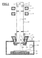
- the particle beam device in FIG. 1 has a beam generator with an electron source (1), an extraction electrode (2), a control electrode (3) and an anode (4).
- the anode (4) forms the source-side end of the beam-guiding tube (21).
- the electron source can be designed as a thermal field emitter. However, the electron source may also be formed as a thermal tungsten emitter or LAB 6 emitter.
- Electrons exiting the cathode (1) form a primary electron beam.
- the electrons are accelerated to anode potential due to a potential difference between the electron emitter (1) and the anode (4).
- the anode potential is usually 1-30 kV positive with respect to the cathode potential, so that the electrons have a kinetic energy in the range between 1 keV and 30 keV.
- the condenser tube (21) is followed by two condenser lenses (5), (6) arranged serially one behind the other. Between the condenser lenses (5), (6), an aperture diaphragm (7) is arranged in the beam guiding tube.
- the objective lens (10) is formed in the illustrated embodiment as a magnetic lens and has a pole piece (22) with a Polschuhspalt (23). In the pole piece (22) an annular coil (11) for generating the magnetic field of the objective lens is arranged.
- the main plane of the objective lens (10) is approximately at the level of the pole piece gap (23), so that - although the sample-side deflection system (12) is physically located in the vicinity of the pole piece gap (23) of the objective lens (10) - this deflection system (12) as well as the source-side deflection system (9) is arranged on the source side before the main plane of the objective lens (10).
- Both beam deflection systems (9), (12) are crossed beam deflection systems, that is to say that each of the two beam deflection systems (9) and (12) can deflect the particle beam in two non-parallel directions which are perpendicular to the direction of the optical axis (20).
- both beam deflection systems are designed as magnetic beam deflection systems and accordingly each have four air coils arranged around the optical axis of the particle beam device.
- the beam deflection systems or at least one of the two beam deflection systems as an electrostatic beam deflection system.
- the relevant would be electrostatic trained Strahlablenksystem have four electrodes, which can be acted upon by different electrostatic potentials.
- the objective lens (10) protrudes from above through an opening into the interior of a sample chamber (13).
- a sample (15) can be recorded on an object table (19).
- the objective lens (10) of the beam generator (1) generated and with the aid of the condenser lenses (5), (6) shaped particle beam in an object plane (16) is focused. In the object plane (16) therefore results in a fine electron probe.
- the distance of the object plane (16) from the lower edge of the objective lens (10) or the lower edge of the pole piece (22) of the objective lens (10) is not fixed, but can be varied by varying the excitation of the objective lens along the optical axis (20) become.
- the particle beam in the object plane (16) can be deflected perpendicular to the optical axis (20), so that by different deflections of the particle beam in the object plane (16) positioned surface of the sample (16 15) can be scanned.
- a detector (14) can be arranged in the sample chamber (13) with which interaction products of the particle beam with the sample (15) or the surface of the sample (15) can be detected.
- a further detector (8) may be arranged in the beam-guiding tube, with the aid of which interaction products of the particle beam with the sample (15) or the surface of the sample (15), which reach the beam-guiding tube (21), can be detected.
- an image of the surface of the sample (15) can be formed .
- a gas inlet system not shown here, to introduce a special precursor gas or process gas into the sample chamber (13) which is chemically activated by the particle beam at the point where the particle beam impinges on the surface of the sample (15) can be.
- a local electron beam-induced etching of the sample (15) or a local, induced by the electron beam deposition of material on the surface of the sample (15) is then possible.
- FIG. 1 Furthermore shown is a pressure stage holder (17), which is on the pole piece (22) of the objective lens, which projects into the sample chamber (13), is receivable.
- the pressure stage holder (17) has an aperture with a small aperture (18).
- Further pressure stage diaphragms are arranged within the beam guide tube (21) and in the FIG. 1 not shown.
- the vacuum pumps which are required for generating and maintaining the required for the operation of the particle beam vacuum within the beam guide tube (21) and the sample chamber (13).
- the pressure level stop (17) is not required and can therefore be removed from the pole piece (22) of the objective lens (10). How to use the FIG. 1 detects, can be scanned in this operating mode, a large image field in the object plane (16), without a mechanical trimming of the particle beam takes place.
- the particle beam device is to be operated at a relatively high pressure in the sample chamber (pressures in the range of approximately 1 to 3000 Pa)
- the pressure stage diaphragm holder (17) must be mounted on the pole piece (22) of the objective lens, thereby within the beam guide tube (21) by differential pumping despite the higher pressure in the sample chamber (13), a sufficiently good vacuum can be maintained.
- the pressure stage diaphragm holder (17) is mounted, the edge of the opening (18) within the pressure stage diaphragm (17) leads to a trimming of the image field which can be scanned in the object plane (16).
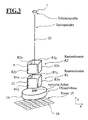
- FIG. 3 is the particle beam system out FIG. 1 once again simplified and shown in perspective.
- the in the FIG. 3 Components shown are provided with the same reference numerals as in the FIG. 1 , How to get the FIG. 3 each of the two deflection systems (9, 12) each has four deflection elements distributed around the optical axis.
- the sample-side deflection system (12) has two deflecting elements R 1X facing each other with respect to the optical axis (20), which deflect in a first spatial direction (X direction).
- the sample-side deflection system (12) has two deflecting elements R 1Y facing each other with respect to the optical axis (20), upon excitation of which the particle beam is deflected in the direction of a second spatial direction (Y direction), which ideally corresponds to the first spatial direction (X Direction) is vertical,
- the source-side deflection system (9) has four deflection elements R 2X , R 2Y , of which in turn two are parallel and the other two offset by approximately 90 degrees about the optical axis (20) are arranged.
- the second deflection system (9) causes an excitation of the deflection R 2X a deflection of the particle in the first direction (X-direction) and an excitation of the substantially perpendicular pair of deflectors R 2Y a deflection of the particle substantially perpendicular to the first direction ,
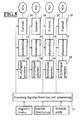
- the control circuit has for each deflection element R 1X , R 1Y , R 2X , R 2Y of the two deflection systems (9,12) a series circuit of a mixer (44), an attenuator (45), the height of the output signal of an output stage (46). and thus affects the image field size, and an output stage (46).
- the circuit consists of four parallel circuits of mixer (44), attenuator (45) and power amplifier (46).
- Each of the four mixers (44) has as its input the output of an X (t) signal generator (41) and a Y (t) signal generator (42).
- the output signals generated by the two signal generators (41), (42) are in turn determined by a signal generation controller (43).
- a signal generation controller 43
- different linear combinations of the signals provided by the two signal generators (41, 42) are generated by the mixers (44) and after attenuation by an attenuator (45) and amplification by a Output stage (46) to the respective associated deflection element R 1X , R 1Y , R 2X , R 2Y issued.
- Input parameters for the signal conditioning control (47) are the adjustment mode, the image field orientation and the image field size.
- signals are generated by the mixers (44) after attenuation and Final amplification with the aid of the deflection elements R 1X , R 1Y , R 2X , R 2Y produce deflection fields which have different angular orientations to one another,
- FIG. 2a In a first operating mode, the in FIG. 2a is shown, the deflection field generated by the sample-side deflection system (12) with (R 1 ) and the deflection field generated by the source-side deflection system (9) with (R 2 ).
- the two deflection fields (R 1 , R 2 ) have different angular orientations, that is, they include an angle ⁇ 1 .
- the two series-wise deflection fields (R 1 ) and (R 2 ) together with the action of the objective (10) cause a deflection of the particle beam in the object plane (16) in the direction of a first direction (R Ges ).
- the direction (R Ges ) agrees with the X direction of the between FIGS. 2a and 2b Coordinate system represented, that is, by the two deflection fields (R 1 ) and (R 2 ) is carried out a total of a beam deflection of the particle beam in the X direction.
- the deflection field generated by the sample-side deflection system (12) is denoted by (R 1 ) and the deflection field generated by the source-side deflection system (9) is denoted by (R 2 ).
- R 1 the deflection field generated by the sample-side deflection system
- R 2 the deflection field generated by the source-side deflection system
- the angles ⁇ 2 between the two field directions (R 1 ) and (R 2 ) deviate from the angle ⁇ 1 in the first mode of operation.
- R 1 ⁇ x B ⁇ K 1 ⁇ x ⁇ X t ⁇ cos ⁇ + ⁇ 1 ⁇ x - Y t ⁇ sin ⁇ + ⁇ 1 ⁇ x
- R 1 ⁇ y B ⁇ K 1 ⁇ y ⁇ X t ⁇ sin ⁇ + ⁇ 1 ⁇ y + Y t ⁇ cos ⁇ + ⁇ 1 ⁇ y
- R 2 ⁇ x B ⁇ A ⁇ K 2 ⁇ x ⁇ X t ⁇ cos ⁇ + ⁇ + ⁇ 2 ⁇ x - Y t ⁇ sin ⁇ + ⁇ + ⁇ 2 ⁇ x
- R 2 ⁇ y B ⁇ A ⁇ K 2 ⁇ y ⁇ X t ⁇ sin ⁇ + ⁇ + ⁇ 2 ⁇ y + Y t ⁇ cos ⁇ + ⁇ + ⁇ + ⁇ 2 ⁇ x
- R 2 ⁇ y B ⁇ A
- R 1 ⁇ x B ⁇ X t ⁇ cos ⁇ - Y t ⁇ sin ⁇
- R 1 ⁇ y B ⁇ X t ⁇ sin ⁇ + Y t ⁇ cos ⁇
- R 2 ⁇ x B ⁇ A ⁇ X t ⁇ cos ⁇ + ⁇ - Y t ⁇ sin ⁇ + ⁇
- R 2 ⁇ y B ⁇ A ⁇ X t ⁇ sin ⁇ + ⁇ + Y t ⁇ cos ⁇ + ⁇
- the size B allows the size of the field scanned in the object plane to be changed, and the size ⁇ can be used to change the orientation of the image field in the object plane.
- ⁇ describes the angular orientations of the first and the second deflection field in the sample-side deflection system (12) and in the source-side deflection system (9) to each other.
- the formation of the linear combinations in the mixers (44) changes the angle ⁇ , which describes the angular orientation between the deflection fields.
- the size A can also be changed, ie the relative strength of the deflection fields between the sample-side and the source-side deflection system.
- control parameter "image field size” acts on the factor B, the control parameter “image field orientation” on the angle ⁇ and the adjustment mode on the factor A and the angular orientation ⁇ , but indirectly also on the sizes B and ⁇ , if the image field is to remain constant ,
- the output stages (46) can generally be switched between a plurality of voltage ranges for deflection electrodes and current ranges for deflection coils.
- the power amplifiers thus contribute to a weakening of the signal. This is necessary in order to cover the large required dynamic range in terms of image field size without loss of quality.
- control signal conditioning (47) configures the analog mixers (44), the attenuators (45), and the final stages (46).
- the control variable "image field size" with the factor B essentially acts on the attenuator (45) and the output stages (46), while the angle values ⁇ and ⁇ act exclusively on the mixers (44).
- the factor A can be integrated into the signal conditioning both in the mixers (44) and in the attenuators (45) and the output stages (46).
- the functions X (t) and Y (t) already mixed digitally in the control signal conditioning and generation (57) are generated directly in the signal generators (58).
- a separate signal generator (58) is present for each deflection element R 1X , R 1Y , R 2X , R 2Y .
- the control variable B acts analogously in this arrangement to the embodiment in FIG. 4 on the attenuators (55) and the final stages (56) to cover the large dynamic range of the image field size without loss of quality.
- the digital version according to the FIG. 5 has compared to the analog signal conditioning according to the FIG. 4 the disadvantage that four instead of two signal generators are required.
- the embodiment provides in FIG. 5 the advantage that the unavoidable inaccuracies occurring during analog mixing are avoided.
- the number of pixels which an objective lens can transmit without causing additional blurring at the edge of the picture is greater than one Pixel is also limited by artifacts.
- Significant image defects include the extra-axial coma defect, which becomes visible as a tail, and the extra-axial dispersion, which becomes visible as a line. If the illumination aperture is sufficiently small, images with a pixel resolution of 10 000 x 10 000 pixels are possible. However, there are also known applications in which imaging with 30 000 pixels x 30000 pixels are desirable. An example of this is brain mapping with thousands of thin prepared cuts, each of which is to be documented with thousands of high-pixel images.
- the axial aberrations (axial chromatic aberration, spherical aperture error) are so large that only small illumination apertures are usable. Since the off-axis coma error is quadratically dependent on the illumination aperture, its effect is relatively small when using conventional particle optics, and it is therefore possible to record image fields of 10,000 ⁇ 10,000 pixels.
- the axial aberrations are corrected by correctors and the spatial resolution is thereby to be further improved, an increase in the illumination aperture by a factor of 3-10 is required. Only with such larger illumination apertures, the diffraction error becomes sufficiently small.
- the small opening in the pressure step diaphragm usually leads to a limitation of the image field which can be scanned in the object plane.
- This can be avoided in purely electrostatic lenses by using a Doppelablenksystems principle by a virtual tilting point for the particle beam in the plane of the pressure level diaphragm is generated by appropriate control of Doppelablenksystems.
- the Lamor rotation of the magnetic field emerging from the objective lens leads to an additional rotation of the trajectory. This has the consequence that the source-side deflection system deflected and deflected back from the sample-side deflection system particle beam does not intersect the optical axis, but skewed past the optical axis. This effect is in the FIG.
- the trajectory does not intersect the optical axis, but reaches a minimum distance at a point (P), and then the radial distance of the particle trajectory from the optical axis increases again.
- FIG. 7 This problem can be solved by an arrangement as in FIG. 7 eliminate shown.
- the particle source is labeled (201) and the objective lens is labeled (210).
- the objective lens is labeled (210).
- the optical axis are now three crossed deflection systems (209), (212) and (221) arranged serially one behind the other, with one of the three deflection systems, in this case the source-side deflection system (221), rotated about the optical axis (220) relative to the other two deflection systems (209), (212) is arranged.
- the deflection system (221) Since the deflection system (221) is rotated about the optical axis (220) with respect to the deflection systems (209) and (212), the deflection system produces a deflection field that has a changed angular orientation relative to that through the other two deflection systems (209) and (212) Has deflection fields.
- the angular orientation or the changed angular orientation By this additional degree of freedom of the angular orientation or the changed angular orientation, it is now possible to guide the particle beam so that the particle beam intersects the optical axis, as this in the FIG. 9b is shown.
- a pressure stage diaphragm with an arbitrarily small opening can now be arranged which does not lead to a trimming of the image field which can be scanned with the particle beam in the object plane.
- FIG. 8 is an alternative embodiment to the embodiment in the FIG. 7 shown.
- the embodiment in the FIG. 7 has the embodiment in the FIG. 8 three interleaved deflection systems (309), (312), (321) serially connected in series along the optical axis (320) defined by the objective (310).
- all three deflection systems (309), (312), (321) are arranged rotated relative to each other about the optical axis, the relative rotation angle between two successive deflection systems being at least 5 degrees, preferably more than 10 degrees and again preferably more than and 20 degrees.
- the same effect achieved by mutually rotated deflection systems can also be achieved if only two respectively crossed deflection systems are connected in series one behind the other and the control of the deflection systems makes it possible to generate deflection fields with different angular orientations.
- the embodiments with electrically adjustable angular orientations by means of the formation of virtually any linear combination of the deflection fields still provide the advantage that the angular orientation between the deflection fields can be set as desired.
- About the corresponding continuous adjustment of the factor A can be found in the FIG. 9b Adjust the point of intersection of the particle beam with the optical axis so that the image field that can be scanned with the particle beam becomes maximum. As a result, tolerances in the positioning of the pressure level diaphragm can be partially compensated.
- the factor A and the angular orientation ⁇ By changing both the factor A and the angular orientation ⁇ during the operation of the particle beam device, it is possible to adjust the balance as a function of the set magnification. At low magnification, it makes sense to set the factor A and the angle orientation factor ⁇ such that in the object plane the largest possible image field can be scanned with low distortion. At a set higher magnification, If, due to the correspondingly smaller field of view screened with the particle beam, the pressure stage diaphragm no longer delimits the image field, the factor A and the angular orientation ⁇ can be selected such that the number of pixels that can be transmitted without interfering aberations becomes the maximum. It is thereby achieved that, at least at high magnifications, a similarly large number of pixels is available for "variable pressure" operation as can be achieved even during operation of the particle beam apparatus with high vacuum in the sample chamber.
- the invention has been described mainly by means of exemplary embodiments which serve to produce an image of a sample.
- the invention can equally be used with particle beam devices which serve to pattern a sample surface, since the patterning of sample surfaces often involves different requirements for the size of the image field to be structured, the homogeneity of the structure sizes over the image field and the fineness achieved in the structuring the particle probe, which, like the resolution of the imaging particle beam device, is determined by the size of the particle probe in the object plane.
- the particle beam device may have different modes of operation that are user selectable.
- the particle beam deflection in the deflection systems is adjusted for angular orientations between the deflection fields that minimize the aberration that is most negatively impacting the particular application.
- it is also possible to optimize the sum of two or more aberrations by appropriately changing the angular orientation between the deflection fields and / or the amplitude ratios (factor A) so that the sum of the various interfering aberrations becomes minimal.
- a compensation of the distortion is provided by non-linear components in the signal generation (43) for the deflection elements. This has the advantage that, in addition to the distortion, other abovementioned aberrations can then be corrected or minimized via suitable values for ⁇ and A.
Landscapes
- Chemical & Material Sciences (AREA)
- Analytical Chemistry (AREA)
- Analysing Materials By The Use Of Radiation (AREA)
- Electron Beam Exposure (AREA)
- Mechanical Optical Scanning Systems (AREA)
Applications Claiming Priority (1)
| Application Number | Priority Date | Filing Date | Title |
|---|---|---|---|
| DE102010053194A DE102010053194A1 (de) | 2010-12-03 | 2010-12-03 | Teilchenstrahlgerät mit Ablenksystem |
Publications (3)
| Publication Number | Publication Date |
|---|---|
| EP2461346A2 true EP2461346A2 (fr) | 2012-06-06 |
| EP2461346A3 EP2461346A3 (fr) | 2013-12-04 |
| EP2461346B1 EP2461346B1 (fr) | 2018-05-02 |
Family
ID=45044453
Family Applications (1)
| Application Number | Title | Priority Date | Filing Date |
|---|---|---|---|
| EP11191531.0A Active EP2461346B1 (fr) | 2010-12-03 | 2011-12-01 | Appareil à faisceau de particules doté d'un système de déviation |
Country Status (4)
| Country | Link |
|---|---|
| US (1) | US8405045B2 (fr) |
| EP (1) | EP2461346B1 (fr) |
| CN (1) | CN102610479B (fr) |
| DE (1) | DE102010053194A1 (fr) |
Families Citing this family (16)
| Publication number | Priority date | Publication date | Assignee | Title |
|---|---|---|---|---|
| US8604427B2 (en) * | 2012-02-02 | 2013-12-10 | Applied Materials Israel, Ltd. | Three-dimensional mapping using scanning electron microscope images |
| US10049948B2 (en) * | 2012-11-30 | 2018-08-14 | Lam Research Corporation | Power switching system for ESC with array of thermal control elements |
| JP2014212063A (ja) * | 2013-04-19 | 2014-11-13 | 日本電子株式会社 | 走査荷電粒子顕微鏡、走査荷電粒子顕微鏡の制御方法、および走査荷電粒子顕微鏡の軸合わせ方法 |
| US9715724B2 (en) | 2014-07-29 | 2017-07-25 | Applied Materials Israel Ltd. | Registration of CAD data with SEM images |
| WO2016103493A1 (fr) * | 2014-12-26 | 2016-06-30 | 技術研究組合次世代3D積層造形技術総合開発機構 | Dispositif d'impression 3d, procédé de commande de dispositif d'impression 3d et programme de commande |
| US10297418B2 (en) * | 2015-07-14 | 2019-05-21 | ICT Integrated Circuit Testing Gesellschaft für Halbleiterprüftechnik mbH | Method of reducing coma and chromatic aberration in a charged particle beam device, and charged particle beam device |
| WO2017027922A1 (fr) * | 2015-08-18 | 2017-02-23 | Gerasimos Daniel Danilatos | Microscope électronique à balayage atmosphérique à grand champ |
| DE102017205231B3 (de) | 2017-03-28 | 2018-08-09 | Carl Zeiss Microscopy Gmbh | Teilchenoptische Vorrichtung und Teilchenstrahlsystem |
| CN109298001B (zh) * | 2017-07-25 | 2021-06-01 | 东方晶源微电子科技(北京)有限公司 | 电子束成像模块、电子束检测设备及其图像采集方法 |
| JP6631647B2 (ja) * | 2018-03-08 | 2020-01-15 | 株式会社島津製作所 | 走査型プローブ顕微鏡及び表面画像補正方法 |
| DE102018115012A1 (de) | 2018-06-21 | 2019-12-24 | Carl Zeiss Microscopy Gmbh | Teilchenstrahlsystem |
| US11114272B2 (en) * | 2019-09-25 | 2021-09-07 | Fei Company | Pulsed CFE electron source with fast blanker for ultrafast TEM applications |
| DE102020113502A1 (de) * | 2020-05-19 | 2021-11-25 | Carl Zeiss Microscopy Gmbh | Verfahren zum Betreiben eines Teilchenstrahlmikroskops |
| JP7538069B2 (ja) * | 2020-09-23 | 2024-08-21 | 日本電子株式会社 | 対物レンズ、電子顕微鏡、対物レンズのクリーニング方法、および治具 |
| CN116190185A (zh) * | 2021-05-27 | 2023-05-30 | 中科晶源微电子技术(北京)有限公司 | 减小相差的偏转器机构及扫描电镜 |
| DE102021122388A1 (de) * | 2021-08-30 | 2023-03-02 | Carl Zeiss Microscopy Gmbh | Teilchenstrahlsäule |
Citations (1)
| Publication number | Priority date | Publication date | Assignee | Title |
|---|---|---|---|---|
| US6809322B2 (en) | 2000-08-11 | 2004-10-26 | Gerasimos Daniel Danilatos | Environmental scanning electron microscope |
Family Cites Families (7)
| Publication number | Priority date | Publication date | Assignee | Title |
|---|---|---|---|---|
| DD135311A1 (de) | 1978-01-24 | 1979-04-25 | Eberhard Hahn | Verfahren und einrichtung zur korrektur der ablenkaberrationen in einem korpuskularstrahlgeraet |
| GB2164202A (en) * | 1984-09-05 | 1986-03-12 | Philips Electronic Associated | Charged particle beam apparatus |
| US6376842B1 (en) * | 1998-03-16 | 2002-04-23 | Nikon Corporation | Optical system for charged-particle-beam microlithography apparatus exhibiting reduced third- and fifth-order aberrations |
| EP0999573B1 (fr) * | 1998-11-06 | 2006-06-28 | ICT Integrated Circuit Testing Gesellschaft für Halbleiterprüftechnik mbH | Colonne de faisceau de particules chargées |
| US6123123A (en) | 1999-08-03 | 2000-09-26 | M. Carder Industries, Incorporated | Non-stretch breakaway hose particularly for fuel dispenser |
| US7315029B2 (en) * | 2005-09-30 | 2008-01-01 | Applied Materials, Inc. | Electrostatic deflection system with low aberrations and vertical beam incidence |
| JP4922747B2 (ja) * | 2006-12-19 | 2012-04-25 | 日本電子株式会社 | 荷電粒子ビーム装置 |
-
2010
- 2010-12-03 DE DE102010053194A patent/DE102010053194A1/de not_active Withdrawn
-
2011
- 2011-11-29 US US13/306,529 patent/US8405045B2/en active Active
- 2011-12-01 EP EP11191531.0A patent/EP2461346B1/fr active Active
- 2011-12-05 CN CN201110463206.4A patent/CN102610479B/zh active Active
Patent Citations (1)
| Publication number | Priority date | Publication date | Assignee | Title |
|---|---|---|---|---|
| US6809322B2 (en) | 2000-08-11 | 2004-10-26 | Gerasimos Daniel Danilatos | Environmental scanning electron microscope |
Also Published As
| Publication number | Publication date |
|---|---|
| US8405045B2 (en) | 2013-03-26 |
| CN102610479B (zh) | 2016-08-17 |
| DE102010053194A1 (de) | 2012-06-06 |
| EP2461346B1 (fr) | 2018-05-02 |
| US20120138814A1 (en) | 2012-06-07 |
| CN102610479A (zh) | 2012-07-25 |
| EP2461346A3 (fr) | 2013-12-04 |
Similar Documents
| Publication | Publication Date | Title |
|---|---|---|
| EP2461346B1 (fr) | Appareil à faisceau de particules doté d'un système de déviation | |
| DE102018202728B4 (de) | Verfahren zum Betrieb eines Teilchenstrahlgeräts, Computerprogrammprodukt und Teilchenstrahlgerät zur Durchführung des Verfahrens | |
| DE102020107738B3 (de) | Teilchenstrahl-System mit einer Multipol-Linsen-Sequenz zur unabhängigen Fokussierung einer Vielzahl von Einzel-Teilchenstrahlen, seine Verwendung und zugehöriges Verfahren | |
| DE102016208689B4 (de) | Verfahren zum Erzeugen eines Bildes eines Objekts und/oder einer Darstellung von Daten über das Objekt sowie Computerprogrammprodukt und Teilchenstrahlgerät zur Durchführung des Verfahrens | |
| DE112011104595B4 (de) | Vorrichtung mit einem geladenen Teilchenstrahl sowie Verfahren zur Steuerung | |
| EP3712924B1 (fr) | Dispositif et procédé de transfert d'électrons d'un échantillon à un analyseur d'énergie et dispositif spectromètre d'électrons | |
| EP1277221A1 (fr) | Canon electronique pour electrons ou faisceaux ioniques de haute monochromie ou de haute densite de courant | |
| DE112014003890T5 (de) | Mit einem Strahl geladener Teilchen arbeitende Vorrichtung | |
| DE112016005577T5 (de) | Ladungsträgerstrahlvorrichtung und Verfahren zur Einstellung ihrer optischen Achse | |
| DE102017203553A1 (de) | Objektpräparationseinrichtung und Teilchenstrahlgerät mit einer Objektpräparationseinrichtung sowie Verfahren zum Betrieb des Teilchenstrahlgeräts | |
| DE112010004145B4 (de) | Vorrichtung zur Abtastung mit einem geladenen Teilchenstrahl und Vefahren zur Korrektur der chromatischen und sphärischen Aberration in Kombination | |
| DE102019202838A1 (de) | Strahlbestrahlungsvorrichtung | |
| DE10122957A1 (de) | Ablenksystem für ein Teilchenstrahlgerät | |
| DE602004012056T2 (de) | Fokussierlinse für Strahlen geladener Teilchen | |
| EP0603555A1 (fr) | Procédé d'illumination par un faisceau d'électron focalisé et système d'optique électronique d'illumination pour la mise en oeuvre dudit procédé | |
| DE102017203554A1 (de) | Objektpräparationseinrichtung und Teilchenstrahlgerät mit einer Objektpräparationseinrichtung sowie Verfahren zum Betrieb des Teilchenstrahlgeräts | |
| DE102015210893B4 (de) | Analyseeinrichtung zur Analyse der Energie geladener Teilchen und Teilchenstrahlgerät mit einer Analyseeinrichtung | |
| DE102019203579A1 (de) | Verfahren zum Betrieb eines Teilchenstrahlgeräts sowie Teilchenstrahlgerät zur Durchführung des Verfahrens | |
| EP1006556B1 (fr) | APPAREIL D'OPTIQUE PARTICULAIRE pour la fabrication de microstructures | |
| DE102023131607B4 (de) | Verfahren zum Betreiben einer Teilchenstrahlvorrichtung, Computerprogrammprodukt und Teilchenstrahlvorrichtung zum Ausführen des Verfahrens | |
| DE102024105423A1 (de) | Verfahren zum Ermitteln der Bildschärfe eines teilchenoptischen Bildes, Verfahren zum automatisierten Justieren eines Teilchenstrahlsystems hinsichtlich seiner Bildschärfe, Computerprogrammprodukt und Teilchenstrahlsystem | |
| DE112013002323T5 (de) | Ladungsteilchenstrahlvorrichtung | |
| EP1454334A2 (fr) | Systeme de lentilles presentant un axe optique lateralement depla able con u pour un rayonnement corpusculaire | |
| DE102021102900B4 (de) | Verfahren zum Betrieb eines Teilchenstrahlgeräts, Computerprogrammprodukt und Teilchenstrahlgerät zur Durchführung des Verfahrens | |
| DE102018010335B9 (de) | Verfahren zum Betrieb eines Teilchenstrahlgeräts, Computerprogrammprodukt und Teilchenstrahlgerät zur Durchführung des Verfahrens |
Legal Events
| Date | Code | Title | Description |
|---|---|---|---|
| PUAI | Public reference made under article 153(3) epc to a published international application that has entered the european phase |
Free format text: ORIGINAL CODE: 0009012 |
|
| AK | Designated contracting states |
Kind code of ref document: A2 Designated state(s): AL AT BE BG CH CY CZ DE DK EE ES FI FR GB GR HR HU IE IS IT LI LT LU LV MC MK MT NL NO PL PT RO RS SE SI SK SM TR |
|
| AX | Request for extension of the european patent |
Extension state: BA ME |
|
| PUAL | Search report despatched |
Free format text: ORIGINAL CODE: 0009013 |
|
| AK | Designated contracting states |
Kind code of ref document: A3 Designated state(s): AL AT BE BG CH CY CZ DE DK EE ES FI FR GB GR HR HU IE IS IT LI LT LU LV MC MK MT NL NO PL PT RO RS SE SI SK SM TR |
|
| AX | Request for extension of the european patent |
Extension state: BA ME |
|
| RIC1 | Information provided on ipc code assigned before grant |
Ipc: H01J 37/147 20060101AFI20131029BHEP Ipc: H01J 37/28 20060101ALI20131029BHEP |
|
| 17P | Request for examination filed |
Effective date: 20140528 |
|
| RBV | Designated contracting states (corrected) |
Designated state(s): AL AT BE BG CH CY CZ DE DK EE ES FI FR GB GR HR HU IE IS IT LI LT LU LV MC MK MT NL NO PL PT RO RS SE SI SK SM TR |
|
| RAP1 | Party data changed (applicant data changed or rights of an application transferred) |
Owner name: CARL ZEISS NTS LTD. Owner name: CARL ZEISS MICROSCOPY GMBH |
|
| STAA | Information on the status of an ep patent application or granted ep patent |
Free format text: STATUS: EXAMINATION IS IN PROGRESS |
|
| 17Q | First examination report despatched |
Effective date: 20170327 |
|
| GRAP | Despatch of communication of intention to grant a patent |
Free format text: ORIGINAL CODE: EPIDOSNIGR1 |
|
| STAA | Information on the status of an ep patent application or granted ep patent |
Free format text: STATUS: GRANT OF PATENT IS INTENDED |
|
| RAP1 | Party data changed (applicant data changed or rights of an application transferred) |
Owner name: CARL ZEISS MICROSCOPY LIMITED Owner name: CARL ZEISS MICROSCOPY GMBH |
|
| INTG | Intention to grant announced |
Effective date: 20170927 |
|
| GRAJ | Information related to disapproval of communication of intention to grant by the applicant or resumption of examination proceedings by the epo deleted |
Free format text: ORIGINAL CODE: EPIDOSDIGR1 |
|
| STAA | Information on the status of an ep patent application or granted ep patent |
Free format text: STATUS: EXAMINATION IS IN PROGRESS |
|
| GRAP | Despatch of communication of intention to grant a patent |
Free format text: ORIGINAL CODE: EPIDOSNIGR1 |
|
| STAA | Information on the status of an ep patent application or granted ep patent |
Free format text: STATUS: GRANT OF PATENT IS INTENDED |
|
| INTC | Intention to grant announced (deleted) | ||
| INTG | Intention to grant announced |
Effective date: 20171212 |
|
| GRAS | Grant fee paid |
Free format text: ORIGINAL CODE: EPIDOSNIGR3 |
|
| GRAA | (expected) grant |
Free format text: ORIGINAL CODE: 0009210 |
|
| STAA | Information on the status of an ep patent application or granted ep patent |
Free format text: STATUS: THE PATENT HAS BEEN GRANTED |
|
| AK | Designated contracting states |
Kind code of ref document: B1 Designated state(s): AL AT BE BG CH CY CZ DE DK EE ES FI FR GB GR HR HU IE IS IT LI LT LU LV MC MK MT NL NO PL PT RO RS SE SI SK SM TR |
|
| REG | Reference to a national code |
Ref country code: GB Ref legal event code: FG4D Free format text: NOT ENGLISH |
|
| REG | Reference to a national code |
Ref country code: CH Ref legal event code: EP Ref country code: AT Ref legal event code: REF Ref document number: 996115 Country of ref document: AT Kind code of ref document: T Effective date: 20180515 |
|
| REG | Reference to a national code |
Ref country code: DE Ref legal event code: R096 Ref document number: 502011014121 Country of ref document: DE Ref country code: IE Ref legal event code: FG4D Free format text: LANGUAGE OF EP DOCUMENT: GERMAN |
|
| REG | Reference to a national code |
Ref country code: NL Ref legal event code: FP |
|
| REG | Reference to a national code |
Ref country code: LT Ref legal event code: MG4D |
|
| PG25 | Lapsed in a contracting state [announced via postgrant information from national office to epo] |
Ref country code: ES Free format text: LAPSE BECAUSE OF FAILURE TO SUBMIT A TRANSLATION OF THE DESCRIPTION OR TO PAY THE FEE WITHIN THE PRESCRIBED TIME-LIMIT Effective date: 20180502 Ref country code: LT Free format text: LAPSE BECAUSE OF FAILURE TO SUBMIT A TRANSLATION OF THE DESCRIPTION OR TO PAY THE FEE WITHIN THE PRESCRIBED TIME-LIMIT Effective date: 20180502 Ref country code: SE Free format text: LAPSE BECAUSE OF FAILURE TO SUBMIT A TRANSLATION OF THE DESCRIPTION OR TO PAY THE FEE WITHIN THE PRESCRIBED TIME-LIMIT Effective date: 20180502 Ref country code: NO Free format text: LAPSE BECAUSE OF FAILURE TO SUBMIT A TRANSLATION OF THE DESCRIPTION OR TO PAY THE FEE WITHIN THE PRESCRIBED TIME-LIMIT Effective date: 20180802 Ref country code: FI Free format text: LAPSE BECAUSE OF FAILURE TO SUBMIT A TRANSLATION OF THE DESCRIPTION OR TO PAY THE FEE WITHIN THE PRESCRIBED TIME-LIMIT Effective date: 20180502 Ref country code: BG Free format text: LAPSE BECAUSE OF FAILURE TO SUBMIT A TRANSLATION OF THE DESCRIPTION OR TO PAY THE FEE WITHIN THE PRESCRIBED TIME-LIMIT Effective date: 20180802 |
|
| PG25 | Lapsed in a contracting state [announced via postgrant information from national office to epo] |
Ref country code: HR Free format text: LAPSE BECAUSE OF FAILURE TO SUBMIT A TRANSLATION OF THE DESCRIPTION OR TO PAY THE FEE WITHIN THE PRESCRIBED TIME-LIMIT Effective date: 20180502 Ref country code: LV Free format text: LAPSE BECAUSE OF FAILURE TO SUBMIT A TRANSLATION OF THE DESCRIPTION OR TO PAY THE FEE WITHIN THE PRESCRIBED TIME-LIMIT Effective date: 20180502 Ref country code: RS Free format text: LAPSE BECAUSE OF FAILURE TO SUBMIT A TRANSLATION OF THE DESCRIPTION OR TO PAY THE FEE WITHIN THE PRESCRIBED TIME-LIMIT Effective date: 20180502 Ref country code: GR Free format text: LAPSE BECAUSE OF FAILURE TO SUBMIT A TRANSLATION OF THE DESCRIPTION OR TO PAY THE FEE WITHIN THE PRESCRIBED TIME-LIMIT Effective date: 20180803 |
|
| PG25 | Lapsed in a contracting state [announced via postgrant information from national office to epo] |
Ref country code: PT Free format text: LAPSE BECAUSE OF FAILURE TO SUBMIT A TRANSLATION OF THE DESCRIPTION OR TO PAY THE FEE WITHIN THE PRESCRIBED TIME-LIMIT Effective date: 20180903 |
|
| PG25 | Lapsed in a contracting state [announced via postgrant information from national office to epo] |
Ref country code: SK Free format text: LAPSE BECAUSE OF FAILURE TO SUBMIT A TRANSLATION OF THE DESCRIPTION OR TO PAY THE FEE WITHIN THE PRESCRIBED TIME-LIMIT Effective date: 20180502 Ref country code: PL Free format text: LAPSE BECAUSE OF FAILURE TO SUBMIT A TRANSLATION OF THE DESCRIPTION OR TO PAY THE FEE WITHIN THE PRESCRIBED TIME-LIMIT Effective date: 20180502 Ref country code: DK Free format text: LAPSE BECAUSE OF FAILURE TO SUBMIT A TRANSLATION OF THE DESCRIPTION OR TO PAY THE FEE WITHIN THE PRESCRIBED TIME-LIMIT Effective date: 20180502 Ref country code: EE Free format text: LAPSE BECAUSE OF FAILURE TO SUBMIT A TRANSLATION OF THE DESCRIPTION OR TO PAY THE FEE WITHIN THE PRESCRIBED TIME-LIMIT Effective date: 20180502 Ref country code: RO Free format text: LAPSE BECAUSE OF FAILURE TO SUBMIT A TRANSLATION OF THE DESCRIPTION OR TO PAY THE FEE WITHIN THE PRESCRIBED TIME-LIMIT Effective date: 20180502 |
|
| REG | Reference to a national code |
Ref country code: DE Ref legal event code: R097 Ref document number: 502011014121 Country of ref document: DE |
|
| PG25 | Lapsed in a contracting state [announced via postgrant information from national office to epo] |
Ref country code: SM Free format text: LAPSE BECAUSE OF FAILURE TO SUBMIT A TRANSLATION OF THE DESCRIPTION OR TO PAY THE FEE WITHIN THE PRESCRIBED TIME-LIMIT Effective date: 20180502 Ref country code: IT Free format text: LAPSE BECAUSE OF FAILURE TO SUBMIT A TRANSLATION OF THE DESCRIPTION OR TO PAY THE FEE WITHIN THE PRESCRIBED TIME-LIMIT Effective date: 20180502 |
|
| PLBE | No opposition filed within time limit |
Free format text: ORIGINAL CODE: 0009261 |
|
| STAA | Information on the status of an ep patent application or granted ep patent |
Free format text: STATUS: NO OPPOSITION FILED WITHIN TIME LIMIT |
|
| 26N | No opposition filed |
Effective date: 20190205 |
|
| PG25 | Lapsed in a contracting state [announced via postgrant information from national office to epo] |
Ref country code: SI Free format text: LAPSE BECAUSE OF FAILURE TO SUBMIT A TRANSLATION OF THE DESCRIPTION OR TO PAY THE FEE WITHIN THE PRESCRIBED TIME-LIMIT Effective date: 20180502 |
|
| REG | Reference to a national code |
Ref country code: DE Ref legal event code: R119 Ref document number: 502011014121 Country of ref document: DE |
|
| REG | Reference to a national code |
Ref country code: CH Ref legal event code: PL |
|
| GBPC | Gb: european patent ceased through non-payment of renewal fee |
Effective date: 20181201 |
|
| PG25 | Lapsed in a contracting state [announced via postgrant information from national office to epo] |
Ref country code: LU Free format text: LAPSE BECAUSE OF NON-PAYMENT OF DUE FEES Effective date: 20181201 Ref country code: MC Free format text: LAPSE BECAUSE OF FAILURE TO SUBMIT A TRANSLATION OF THE DESCRIPTION OR TO PAY THE FEE WITHIN THE PRESCRIBED TIME-LIMIT Effective date: 20180502 |
|
| REG | Reference to a national code |
Ref country code: IE Ref legal event code: MM4A |
|
| REG | Reference to a national code |
Ref country code: BE Ref legal event code: MM Effective date: 20181231 |
|
| PG25 | Lapsed in a contracting state [announced via postgrant information from national office to epo] |
Ref country code: IE Free format text: LAPSE BECAUSE OF NON-PAYMENT OF DUE FEES Effective date: 20181201 Ref country code: DE Free format text: LAPSE BECAUSE OF NON-PAYMENT OF DUE FEES Effective date: 20190702 Ref country code: FR Free format text: LAPSE BECAUSE OF NON-PAYMENT OF DUE FEES Effective date: 20181231 |
|
| PG25 | Lapsed in a contracting state [announced via postgrant information from national office to epo] |
Ref country code: AL Free format text: LAPSE BECAUSE OF FAILURE TO SUBMIT A TRANSLATION OF THE DESCRIPTION OR TO PAY THE FEE WITHIN THE PRESCRIBED TIME-LIMIT Effective date: 20180502 Ref country code: BE Free format text: LAPSE BECAUSE OF NON-PAYMENT OF DUE FEES Effective date: 20181231 |
|
| PG25 | Lapsed in a contracting state [announced via postgrant information from national office to epo] |
Ref country code: GB Free format text: LAPSE BECAUSE OF NON-PAYMENT OF DUE FEES Effective date: 20181201 Ref country code: CH Free format text: LAPSE BECAUSE OF NON-PAYMENT OF DUE FEES Effective date: 20181231 Ref country code: LI Free format text: LAPSE BECAUSE OF NON-PAYMENT OF DUE FEES Effective date: 20181231 |
|
| PG25 | Lapsed in a contracting state [announced via postgrant information from national office to epo] |
Ref country code: MT Free format text: LAPSE BECAUSE OF FAILURE TO SUBMIT A TRANSLATION OF THE DESCRIPTION OR TO PAY THE FEE WITHIN THE PRESCRIBED TIME-LIMIT Effective date: 20180502 |
|
| REG | Reference to a national code |
Ref country code: AT Ref legal event code: MM01 Ref document number: 996115 Country of ref document: AT Kind code of ref document: T Effective date: 20181201 |
|
| PG25 | Lapsed in a contracting state [announced via postgrant information from national office to epo] |
Ref country code: TR Free format text: LAPSE BECAUSE OF FAILURE TO SUBMIT A TRANSLATION OF THE DESCRIPTION OR TO PAY THE FEE WITHIN THE PRESCRIBED TIME-LIMIT Effective date: 20180502 |
|
| PG25 | Lapsed in a contracting state [announced via postgrant information from national office to epo] |
Ref country code: AT Free format text: LAPSE BECAUSE OF NON-PAYMENT OF DUE FEES Effective date: 20181201 |
|
| PG25 | Lapsed in a contracting state [announced via postgrant information from national office to epo] |
Ref country code: MK Free format text: LAPSE BECAUSE OF NON-PAYMENT OF DUE FEES Effective date: 20180502 Ref country code: CY Free format text: LAPSE BECAUSE OF FAILURE TO SUBMIT A TRANSLATION OF THE DESCRIPTION OR TO PAY THE FEE WITHIN THE PRESCRIBED TIME-LIMIT Effective date: 20180502 Ref country code: HU Free format text: LAPSE BECAUSE OF FAILURE TO SUBMIT A TRANSLATION OF THE DESCRIPTION OR TO PAY THE FEE WITHIN THE PRESCRIBED TIME-LIMIT; INVALID AB INITIO Effective date: 20111201 |
|
| PG25 | Lapsed in a contracting state [announced via postgrant information from national office to epo] |
Ref country code: IS Free format text: LAPSE BECAUSE OF FAILURE TO SUBMIT A TRANSLATION OF THE DESCRIPTION OR TO PAY THE FEE WITHIN THE PRESCRIBED TIME-LIMIT Effective date: 20180902 |
|
| PGFP | Annual fee paid to national office [announced via postgrant information from national office to epo] |
Ref country code: NL Payment date: 20251219 Year of fee payment: 15 |
|
| PGFP | Annual fee paid to national office [announced via postgrant information from national office to epo] |
Ref country code: CZ Payment date: 20251125 Year of fee payment: 15 |