EP2461408A1 - Membrane régulant l'alimentation en carburant, circuit imprimé et pile à combustible - Google Patents
Membrane régulant l'alimentation en carburant, circuit imprimé et pile à combustible Download PDFInfo
- Publication number
- EP2461408A1 EP2461408A1 EP11188448A EP11188448A EP2461408A1 EP 2461408 A1 EP2461408 A1 EP 2461408A1 EP 11188448 A EP11188448 A EP 11188448A EP 11188448 A EP11188448 A EP 11188448A EP 2461408 A1 EP2461408 A1 EP 2461408A1
- Authority
- EP
- European Patent Office
- Prior art keywords
- fuel
- pores
- anisotropic
- insulating layer
- supply amount
- Prior art date
- Legal status (The legal status is an assumption and is not a legal conclusion. Google has not performed a legal analysis and makes no representation as to the accuracy of the status listed.)
- Granted
Links
Images


Classifications
-
- H—ELECTRICITY
- H01—ELECTRIC ELEMENTS
- H01M—PROCESSES OR MEANS, e.g. BATTERIES, FOR THE DIRECT CONVERSION OF CHEMICAL ENERGY INTO ELECTRICAL ENERGY
- H01M8/00—Fuel cells; Manufacture thereof
- H01M8/04—Auxiliary arrangements, e.g. for control of pressure or for circulation of fluids
- H01M8/04082—Arrangements for control of reactant parameters, e.g. pressure or concentration
- H01M8/04201—Reactant storage and supply, e.g. means for feeding, pipes
-
- H—ELECTRICITY
- H01—ELECTRIC ELEMENTS
- H01M—PROCESSES OR MEANS, e.g. BATTERIES, FOR THE DIRECT CONVERSION OF CHEMICAL ENERGY INTO ELECTRICAL ENERGY
- H01M8/00—Fuel cells; Manufacture thereof
- H01M8/04—Auxiliary arrangements, e.g. for control of pressure or for circulation of fluids
-
- H—ELECTRICITY
- H01—ELECTRIC ELEMENTS
- H01M—PROCESSES OR MEANS, e.g. BATTERIES, FOR THE DIRECT CONVERSION OF CHEMICAL ENERGY INTO ELECTRICAL ENERGY
- H01M8/00—Fuel cells; Manufacture thereof
- H01M8/02—Details
- H01M8/0202—Collectors; Separators, e.g. bipolar separators; Interconnectors
- H01M8/0247—Collectors; Separators, e.g. bipolar separators; Interconnectors characterised by the form
-
- H—ELECTRICITY
- H01—ELECTRIC ELEMENTS
- H01M—PROCESSES OR MEANS, e.g. BATTERIES, FOR THE DIRECT CONVERSION OF CHEMICAL ENERGY INTO ELECTRICAL ENERGY
- H01M8/00—Fuel cells; Manufacture thereof
- H01M8/02—Details
- H01M8/0202—Collectors; Separators, e.g. bipolar separators; Interconnectors
- H01M8/0269—Separators, collectors or interconnectors including a printed circuit board
-
- H—ELECTRICITY
- H01—ELECTRIC ELEMENTS
- H01M—PROCESSES OR MEANS, e.g. BATTERIES, FOR THE DIRECT CONVERSION OF CHEMICAL ENERGY INTO ELECTRICAL ENERGY
- H01M8/00—Fuel cells; Manufacture thereof
- H01M8/04—Auxiliary arrangements, e.g. for control of pressure or for circulation of fluids
- H01M8/04082—Arrangements for control of reactant parameters, e.g. pressure or concentration
- H01M8/04186—Arrangements for control of reactant parameters, e.g. pressure or concentration of liquid-charged or electrolyte-charged reactants
-
- H—ELECTRICITY
- H01—ELECTRIC ELEMENTS
- H01M—PROCESSES OR MEANS, e.g. BATTERIES, FOR THE DIRECT CONVERSION OF CHEMICAL ENERGY INTO ELECTRICAL ENERGY
- H01M8/00—Fuel cells; Manufacture thereof
- H01M8/06—Combination of fuel cells with means for production of reactants or for treatment of residues
-
- H—ELECTRICITY
- H01—ELECTRIC ELEMENTS
- H01M—PROCESSES OR MEANS, e.g. BATTERIES, FOR THE DIRECT CONVERSION OF CHEMICAL ENERGY INTO ELECTRICAL ENERGY
- H01M8/00—Fuel cells; Manufacture thereof
- H01M8/10—Fuel cells with solid electrolytes
-
- H—ELECTRICITY
- H01—ELECTRIC ELEMENTS
- H01M—PROCESSES OR MEANS, e.g. BATTERIES, FOR THE DIRECT CONVERSION OF CHEMICAL ENERGY INTO ELECTRICAL ENERGY
- H01M8/00—Fuel cells; Manufacture thereof
- H01M8/10—Fuel cells with solid electrolytes
- H01M8/1009—Fuel cells with solid electrolytes with one of the reactants being liquid, solid or liquid-charged
- H01M8/1011—Direct alcohol fuel cells [DAFC], e.g. direct methanol fuel cells [DMFC]
-
- H—ELECTRICITY
- H01—ELECTRIC ELEMENTS
- H01M—PROCESSES OR MEANS, e.g. BATTERIES, FOR THE DIRECT CONVERSION OF CHEMICAL ENERGY INTO ELECTRICAL ENERGY
- H01M8/00—Fuel cells; Manufacture thereof
- H01M8/02—Details
- H01M8/0202—Collectors; Separators, e.g. bipolar separators; Interconnectors
- H01M8/023—Porous and characterised by the material
- H01M8/0239—Organic resins; Organic polymers
-
- Y—GENERAL TAGGING OF NEW TECHNOLOGICAL DEVELOPMENTS; GENERAL TAGGING OF CROSS-SECTIONAL TECHNOLOGIES SPANNING OVER SEVERAL SECTIONS OF THE IPC; TECHNICAL SUBJECTS COVERED BY FORMER USPC CROSS-REFERENCE ART COLLECTIONS [XRACs] AND DIGESTS
- Y02—TECHNOLOGIES OR APPLICATIONS FOR MITIGATION OR ADAPTATION AGAINST CLIMATE CHANGE
- Y02E—REDUCTION OF GREENHOUSE GAS [GHG] EMISSIONS, RELATED TO ENERGY GENERATION, TRANSMISSION OR DISTRIBUTION
- Y02E60/00—Enabling technologies; Technologies with a potential or indirect contribution to GHG emissions mitigation
- Y02E60/30—Hydrogen technology
- Y02E60/50—Fuel cells
Definitions
- JP 2009-129588 A discusses a single cell for a fuel cell with an electrolyte film interposed between an anode and a cathode.
- a holder composed of a porous polyurethane foam is arranged on a surface outside the anode, and an oxidant permeable layer is arranged on a surface outside the cathode.
- a fuel such as methanol is supplied to the anode after penetrating the holder, and an oxidant is supplied to the cathode after penetrating the oxidant permeable layer.
- the present invention is directed to a fuel supply amount adjustment film capable of preventing a fuel from oozing out on its side surfaces while properly adjusting an amount of supply of a fuel to a cell element, a printed circuit board, and a fuel cell.
- a fuel supply amount adjustment film used for a fuel cell includes an insulating layer having a plurality of anisotropic through pores.
- the fuel supply amount adjustment film can be used to supply a fuel to a cell element in the fuel cell.
- the fuel is supplied to the cell element via the plurality of anisotropic through pores of the insulating layer. In this case, the fuel is prevented from oozing out on side surfaces of the fuel supply amount adjustment film. This enables a loss of the fuel to be reduced.
- the pore diameter of each of the plurality of anisotropic through pores and the porosity for the plurality of anisotropic through pores can be optionally set. Therefore, an amount of supply of the fuel to the cell element can be properly adjusted by properly setting the pore diameter of each of the anisotropic through pores and the porosity for the anisotropic through pores in the fuel supply amount adjustment film.
- the insulating layer has a plurality of through pores which extend from one surface to another surface of the layer, but with substantially none of the through pores extending to a side surface of the layer.
- substantially all of the through pores extend between a top surface and a bottom surface of the layer.
- the porosity for the plurality of anisotropic through pores of the insulating layer may be not less than 1 % and not more than 90 %.
- the printed circuit board can be used to supply the fuel to the cell element in the fuel cell while taking out power generated in the cell element to the exterior.
- the power generated in the cell element is taken out to the exterior via the conductor layer.
- the fuel is supplied to the cell element via the plurality of anisotropic through pores in the printed circuit board.
- the fuel is prevented from oozing out on side surfaces of the fuel supply amount adjustment film. This enables a loss of the fuel to be reduced.
- the pore diameter of each of the plurality of anisotropic through pores and the porosity for the plurality of anisotropic through pores can be optionally set. Therefore, the pore diameter of each of the anisotropic through pores and the porosity for the anisotropic through pores in the fuel supply amount adjustment film are properly set so that an amount of supply of the fuel to the cell element can be properly adjusted.
- a fuel cell includes a cell element having a fuel electrode, an electrode that contacts the fuel electrode of the cell element, the fuel supply amount adjustment film according to the one aspect of the present invention, which is opposed to the fuel electrode of the cell element with the electrode sandwiched therebetween, and a casing that accommodates the cell element, the electrode, and the fuel supply amount adjustment film.
- a flexible printed circuit board hereinafter abbreviated as an FPC board
- FPC board flexible printed circuit board
- Fig. 1 (a) is a plan view of an FPC board according to the first embodiment
- Fig. 1 (b) is a sectional view taken along the line A-A of the FPC board illustrated in Fig. 1 (a) .
- Fig. 2 is a schematic sectional view of the base insulating layer 2. As illustrated in Fig. 2 (a) , the base insulating layer 2 has openings h1 on its one surface and the other surface, the openings h1 on the one surface of the base insulating layer 2 and the openings h1 on the other surface thereof communicate with each other without diverging from each other by single communication paths h2, respectively.
- Each of the anisotropic through pores h of the base insulating layer 2 is formed by irradiating the insulating layer 2 with a heavy ion beam to form an ion track therein and etching the ion track, for example.
- the pore diameter of each of the anisotropic through pores h may be not less than 0.01 ⁇ m and not more than 100 ⁇ m, and preferably not less than 0.01 ⁇ m and not more than 20 ⁇ m.
- the porosity for the anisotropic through pores h of the base insulating layer 2 is set to not less than 1 % and not more than 90 %.
- the anisotropic through pores h of the base insulating layer 2 may be formed using laser light or a drill.
- the base insulating layer 2 includes a first insulating portion 2a, a second insulating portion 2b, a third insulating portion 2c, and a fourth insulating portion 2d.
- the first insulating portion 2a and the second insulating portion 2b each have a rectangular shape, and are integrally formed while being adjacent to each other.
- sides that are parallel to a boundary line between the first insulating portion 2a and the second insulating portion 2b are referred to as lateral sides
- a pair of sides that are perpendicular to the lateral sides of the first insulating portion 2a and the second insulating portion 2b are referred to as end sides.
- the third insulating portion 2c is formed to extend outward from a part of the lateral side at a corner of the first insulating portion 2a.
- the fourth insulating portion 2d is formed to extend outward from a part of the lateral side at a corner of the second insulating portion 2b at a diagonal position of the corner of the first insulating portion 2a.
- a bend portion B1 is provided on the boundary line between the first insulating portion 2a and the second insulating portion 2b to divide the base insulating layer 2 into two substantially equal parts.
- the base insulating layer 2 can be bent along the bend portion B1.
- the bend portion B1 may be a shallow groove with a line shape or a mark with a line shape, for example. Alternatively, there may be nothing at the bend portion B1 if the base insulating layer 2 can be bent at the bend portion B1.
- the first insulating portion 2a and the second insulating portion 2b are opposed to each other. In this case, the third insulating portion 2c and the fourth insulating portion 2d are not opposed to each other.
- Rectangular collector portions 3a, 3b, 3c, 3d, 3e, 3f, 3g, 3h, 3i, and 3j, connection conductor portions 3k, 3l, 3m, and 3n, and drawn-out conductor portions 3o and 3p are formed on one surface of the base insulating layer 2 with an adhesive pattern 7 illustrated in Fig. 1 (b) sandwiched therebetween.
- the collector portions 3a to 3j, the connection conductor portions 3k to 3n, and the drawn-out conductor portions 3o and 3p are made of copper, for example.
- any adhesive such as an epoxy resin adhesive, a phenolic resin adhesive, a polyester resin adhesive, an acrylic resin adhesive, or a polyimide adhesive is used as the adhesive pattern 7.
- a photo-acid generating agent is added to the adhesive pattern 7.
- the adhesive pattern 7 is photosensitive.
- connection conductor portions 3k to 3n is formed on the first insulating portion 2a and the second insulating portion 2b to intersect the bend portion B1.
- the connection conductor portion 3k electrically connects the collector portion 3b and the collector portion 3f to each other
- the connection conductor portion 31 electrically connects the collector portion 3c and the collector portion 3g to each other
- the connection conductor portion 3m electrically connects the collector portion 3d and the collector portion 3h to each other
- connection conductor portion 3n electrically connects the collector portion 3e and the collector portion 3i to each other.
- a plurality of (four in this example) openings H11 are formed in a direction of the end sides in each of the collector portions 3a to 3e.
- a plurality of (four in this example) openings H12 are formed in the direction of the end sides in each of the collector portions 3f to 3j.
- the drawn-out conductor portion 3o is formed to linearly extend from an outer short side of the collector portion 3a onto the third insulating portion 2c.
- the drawn-out conductor portion 3p is formed to linearly extend from an outer short side of the collector portion 3j onto the fourth insulating portion 2d.
- a cover layer 6a is formed on the first insulating portion 2a to cover the collector portion 3a and a part of the drawn-out conductor potion 3o.
- the exposed portion of the drawn-out conductor portion 3o is referred to as a drawn-out electrode 5a.
- Cover layers 6b, 6c, 6d, and 6e are formed on the first insulating portion 2a to cover the collector portions 3b to 3e, respectively. The cover layers 6a to 6e contact an upper surface of the first insulating portion 2a inside the openings H11 of the collector portions 3a to 3e, respectively.
- a cover layer 6j is formed on the second insulating portion 2b to cover the collector portion 3j and a part of the drawn-out conductor potion 3p.
- the exposed portion of the drawn-out conductor portion 3p is referred to as a drawn-out electrode 5b.
- Cover layers 6f, 6g, 6h, and 6i are formed on the second insulating portion 2b to cover the collector portions 3f to 3i, respectively.
- the cover layers 6f to 6j contact an upper surface of the second insulating portion 2b inside the openings H12 of the collector portions 3f to 3j, respectively.
- Cover layers 6k, 61, 6m, and 6n are formed on the first insulating portion 2a and the second insulating portion 2b to cover the connection conductor portions 3k to 3n, respectively.
- Each of the cover layers 6a to 6n is made of a resin composition containing a conductive material.
- the resin composition examples include polyester resin, polyurethane resin, polyacrylic resin, epoxy resin, phenolic resin, polyimide resin, polyamide imide resin, or acrylic resin, or a mixture of at least two types of the foregoing resins.
- examples of a conductive material include a carbon material such as carbon black, graphite, carbon nanotube, a carbon fiber, or black lead, metallic particles such as silver, gold (Au), or silver nanoparticles, a conductive polymeric material such as polythiophene or polyaniline, or a mixture of at least two types of the foregoing materials.
- An additive amount of the conductive material may be an amount in which the conductive material can be dispersed in resin.
- the amount of the conductive material to be added to 100 parts by weight of the resin composition is preferably not less than 1 part by weight and not more than 90 parts by weight, more preferably not less than 10 parts by weight and not more than 70 parts by weight, and still more preferably not less than 40 parts by weight and not more than 70 parts by weight.
- FIG. 3 , 4 and 5 are sectional views illustrating steps of the method for manufacturing the FPC board 1, which respectively correspond to sectional views taken along the line A-A illustrated in Fig. 1 .
- a resist film 22 is formed of a photosensitive dry film resist or the like on the conductor layer 30 at a proper temperature and pressure, as illustrated in Fig. 3 (b) .
- the resist film 22 is exposed in a predetermined pattern, followed by development, to form an etching resist pattern 22a, as illustrated in Fig. 3 (c) .
- a region of the conductor layer 30 that is exposed while not covered with the etching resist pattern 22a is removed by etching using ferric chloride, as illustrated in Fig. 3 (d) .
- the etching resist pattern 22a is then removed by a stripping solution, as illustrated in Fig. 4 (a) .
- the collector portions 3a to 3j, the connection conductor portions 3k to 3n, and the drawn-out conductor portions 3o and 3p are formed on the carrier layer 8.
- the plurality of openings H11 are formed in the collector portions 3a to 3e, and the plurality of openings H12 are formed in the collector portions 3f to 3j.
- the collector portions 3a to 3j, the connection conductor portions 3k to 3n, and the drawn-out conductor portions 3o and 3p may be formed on the carrier layer 8 by another method such as sputtering or evaporation.
- the collector portions 3a to 3j, the connection conductor portions 3k to 3n, and the drawn-out conductor portions 3o and 3p may be formed on the carrier layer 8 by plating using the carrier layer 8 composed of stainless steel.
- the conductor layer 30 is punched out into patterns of collector portions 3a to 3j, the connection conductor portions 3k to 3n, and the drawn-out conductor portions 3o and 3p using laser light or a die, and the patterns obtained by the punching may be joined to the carrier layer 8 using an adhesive or the like.
- the adhesive layer precursor 7p When the adhesive layer precursor 7p is negative photosensitive, the adhesive layer precursor 7p is exposed with a mask pattern having an inverted shape of the collector portions 3a to 3j, the connection conductor portions 3k to 3n, and the drawn-out conductor portions 3o and 3p sandwiched therebetween.
- the adhesive layer precursor 7p When the adhesive layer precursor 7p is positive photosensitive, the adhesive layer precursor 7p is exposed with a mask pattern having the same shape as the collector portions 3a to 3j, the connection conductor portions 3k to 3n, and the drawn-out conductor portions 3o and 3p sandwiched therebetween.
- the adhesive layer precursor 7p When the adhesive layer precursor 7p is positive photosensitive, the adhesive layer precursor 7p may be exposed from its lower surface (a surface in contact with the collector portions 3a to 3j, the connection conductor portions 3k to 3n, and the drawn-out conductor portions 3o and 3p). In this case, the collector portions 3a to 3j, the connection conductor portions 3k to 3n, and the drawn-out conductor portions 3o and 3p can be used as the mask pattern. Thus, a separate mask pattern need not be used. This results in reduction in manufacturing steps and cost of the FPC board 1.
- the carrier layer 8 made of PET transmits exposure light, and therefore does not prevent the adhesive layer precursor 7p from being exposed from its lower surface (a surface in contact with the collector portions 3a to 3j, the connection conductor portions 3k to 3n, and the drawn-out conductor portions 3o and 3p).
- the applied adhesive layer precursor 7p excluding its portions on the collector portions 3a to 3j, the connection conductor portions 3k to 3n, and the drawn-out conductor portions 3o and 3p may be removed by a chemical solution, laser light or plasma processing.
- the mask pattern need not be used during exposure of the adhesive layer precursor 7p.
- the adhesive layer precursor 7p may be applied only on the collector portions 3a to 3j, the connection conductor portions 3k to 3n, and the drawn-out conductor portions 3o and 3p by screen printing or a paste dispenser. Also in this case, the mask pattern need not be used during exposure of the adhesive layer precursor 7p.
- the base insulating layer 2 having the anisotropic through pores h, illustrated in Fig. 2 is joined onto the collector portions 3a to 3j, the connection conductor portions 3k to 3n, and the drawn-out conductor portions 3o and 3p with the adhesive pattern 7 sandwiched therebetween, as illustrated in Fig. 4 (d) .
- the collector portions 3a to 3j, the connection conductor portions 3k to 3n, and the drawn-out conductor portions 3o and 3p may be joined to the base insulating layer 2 in a humidified state or a vacuum state.
- the adhesive pattern 7 may be cured at any temperature, pressure, and degree of vacuum after the joining.
- the carrier layer 8 is then separated from the collector portions 3a to 3j, the connection conductor portions 3k to 3n, and the drawn-out conductor portions 3o and 3p, as illustrated in Fig. 5 (a) .
- the cover layers 6a to 6n are formed by application or lamination on the base insulating layer 2 to cover the collector portions 3a to 3j, the connection conductor portions 3k to 3n, and the drawn-out conductor portions 3o and 3p, as illustrated in Fig. 5 (b) .
- the drawn-out electrodes 5a and 5b are exposed while not covered with the cover layers 6a and 6j.
- the top and bottom of the sectional views of Figs. 5 (b) and 5 (c) are reverse to those of the sectional view of Fig. 5 (a) .
- the base insulating layer 2 is cut in a predetermined shape, so that the FPC board 1 including the base insulating layer 2, the collector portions 3a to 3j, the connection conductor portions 3k to 3n, the drawn-out conductor portions 3o and 3p, and the cover layers 6a to 6n is completed, as illustrated in Fig. 5 (c) .
- the thickness of the base insulating layer 2 is preferably not less than 5 ⁇ m and not more than 500 ⁇ m. If the thickness of the base insulating layer 2 is 5 ⁇ m or more, the durability of the base insulating layer 2 is improved. If the thickness of the base insulating layer 2 is 500 ⁇ m or less, the flexibility and the handleability of the base insulating layer 2 are improved.
- the thicknesses of the collector portions 3a to 3j, the connection conductor portions 3k to 3n, and the drawn-out conductor portions 3o and 3p are preferably not less than 1 ⁇ m and not more than 100 ⁇ m, more preferably not less than 5 ⁇ m and not more than 70 ⁇ m, and still more preferably not less than 10 ⁇ m and not more than 50 ⁇ m.
- the collector portions 3a to 3j, the connection conductor portions 3k to 3n, and the drawn-out conductor portions 3o and 3p improve in durability and an electrical characteristic such as resistance if the thicknesses are 1 ⁇ m or more, and improve in flexibility and handleability if the thicknesses are 100 ⁇ m or less.
- the barrier layer can be sufficiently prevented from dropping out of the collector portions 3a to 3j, the connection conductor portions 3k to 3n, and the drawn-out conductor portions 3o and 3p. If the thicknesses are 100 ⁇ m or less, the cover layers 6a to 6n improve in flexibility and handleability.
- the FPC board 1 is manufactured by a subtractive method in Figs. 3 to 5
- the present invention is not limited to this.
- another manufacturing method such as a semi-additive method may be used.
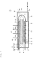
- Fig. 6 is an external perspective view of a fuel cell 100 using the FPC board 1.
- Fig. 7 illustrates functions in the fuel cell 100, and is a sectional view taken along the line B-B of the fuel cell 100 illustrated in Fig. 6 .
- the fuel cell 100 includes a casing 40 having a rectangular parallelepiped shape.
- the casing 40 is indicated by a broken line in Fig. 6 .
- the casing 40 has an upper surface portion 41, a lower surface portion 42, one side surface portion 43, and the other side surface portion 44.
- Fig. 7 does not illustrate the remaining pair of side surface portions.
- the FPC board 1 is sandwiched between the upper surface portion 41 and the lower surface portion 42 of the casing 40 while being bent along the bend portion B1 illustrated in Fig. 1 so that the one surface, on which the cover layers 6a to 6n are formed, is positioned on its inner side.
- the drawn-out electrodes 5a and 5b in the FPC board 1 are drawn out of the one side surface portion 43 of the casing 40. Terminals of various external circuits are electrically connected to the drawn-out electrodes 5a and 5b.
- a plurality of (five in the present embodiment) electrode films 35 are arranged between the cover layer 6a and the cover layer 6f, between the cover layer 6b and the cover layer 6g, between the cover layer 6c and the cover layer 6h, between the cover layer 6d and the cover layer 6i, and between the cover layer 6e and the cover layer 6j, respectively, in the bent FPC board 1 (see Fig. 1 (a) ).
- the plurality of electrode films 35 are connected in series.
- Each of the electrode films 35 includes an air electrode 35a, a fuel electrode 35b, and an electrolyte film 35c.
- the air electrode 35a is formed on one surface of the electrolyte film 35c
- the fuel electrode 35b is formed on the other surface of the electrolyte film 35c.
- the air electrodes 35a in the plurality of electrode films 35 are opposite to the cover layers 6f to 6j in the FPC board 1, respectively, and the fuel electrodes 35b in the plurality of electrode films 35 are opposite to the cover layers 6a to 6e in the FPC board 1, respectively.
- a plurality of openings H41 are formed on the upper surface portion 41 of the casing 40 to correspond to the plurality of openings H12, respectively, of the collector portions 3f to 3j. Air is supplied to the air electrodes 35a in the electrode films 35 via the plurality of openings H41 of the casing 40, the anisotropic through pores h (see Fig. 2 ) of the base insulating layer 2 (see Fig. 2 ), and the plurality of openings H12 of the collector portions 3f to 3j.
- a fuel accommodating chamber 50 is provided on the lower surface portion 42 of the casing 40 to contact the first insulating portion 2a (see Fig. 1 (a) ) of the base insulating layer 2.
- One end of a fuel supply pipe 51 is connected to the fuel accommodating chamber 50.
- the other end of the fuel supply pipe 51 is connected to a fuel supplier (not illustrated) provided outside through the other side surface portion 44 of the casing 40.
- Fuel is supplied from the fuel supplier to the fuel accommodating chamber 50 via the fuel supply pipe 51.
- the fuel is supplied to the fuel electrodes 35b in the electrode films 35 via the anisotropic thorough pores h (see Fig. 2 ) of the base insulating layer 2 and the plurality of openings H11 of the collector portions 3a to 3e.
- methanol is used as the fuel.
- methanol is decomposed into hydrogen ions and carbon dioxide in the plurality of fuel electrodes 35b, to form electrons.
- the formed electrons are led from the collector portion 3a (see Fig. 1 ) to the drawn-out electrode 5a in the FPC board 1.
- Hydrogen ions obtained by decomposing methanol permeate through the electrolyte films 35c to reach the air electrodes 35a.
- hydrogen ions and oxygen are reacted while electrons led from the drawn-out electrode 5b to the collector portion 3j are consumed, to form water. In this manner, electrical power is supplied to the external circuits connected to the drawn-out electrodes 5a and 5b.
- the base insulating layer 2 is used as a fuel supply amount adjustment film in the fuel cell 100.
- a fuel, for the fuel cell 100 such as methanol is supplied to the fuel electrode 35b in the electrode film 35 via the anisotropic through pores h of the base insulating layer 2 in the FPC board 1 and the plurality of openings H11 of the collector portions 3a to 3e.
- the each of anisotropic through pores h communicates with the base insulating layer 2 without diverging from its one surface to the other surface. Therefore, methanol is prevented from oozing out on the side surfaces of the base insulating layer 2. This enables a loss of the fuel to be reduced.
- the pore diameter of each of the anisotropic through pores h and the porosity for the plurality of anisotropic through pores h can be optionally set when each of the anisotropic through pores h is formed. Therefore, the pore diameter of each of the anisotropic through pores h and the porosity for the plurality of anisotropic through pores h of the base insulating layer 2 are properly set so that an amount of supply of methanol to the fuel electrode 35b can be properly adjusted.
- the pore diameter of each of the anisotropic through pores h of the base insulating layer 2 is set to 0.01 ⁇ m or more.
- the fuel can be sufficiently supplied to the fuel electrode 35b in the electrode film 35 via the anisotropic through pores h.
- an output of the fuel cell 100 can be increased.
- the pore diameter of each of the anisotropic through pores h is set to 100 ⁇ m or less.
- the porosity for the anisotropic through pores h of the base insulating layer 2 is set to 1 % or more.
- the fuel can be sufficiently supplied to the fuel electrode 35b in the electrode film 35 via the anisotropic through pores h.
- the porosity for the anisotropic through pores h is set to 90 % or less.
- the crossover of the fuel can be suppressed.
- Fig. 8 is a sectional view of the fuel cell 100 according to the second embodiment. Fig. 8 corresponds to a sectional view taken along a line B-B of the fuel cell 100 illustrated in Fig. 6 .
- the fuel cell 100 has a similar configuration to that of the fuel cell 100 illustrated in Fig. 7 except that an FPC board 1 includes a base insulating layer 2A in place of the base insulating layer 2 illustrated in Fig. 1 and further includes two fuel supply amount adjustment films 2B.
- Each of the fuel supply amount adjustment films 2B has anisotropic through pores h illustrated in Fig. 2 , similarly to the base insulating layer 2 illustrated in Fig. 2 .
- a method for forming the anisotropic through pores h in the fuel supply amount adjustment films 2B, the pore diameter of each of the anisotropic through pores h, the porosity for the anisotropic through pores h in the fuel supply amount adjustment films 2B, and the thickness of the fuel supply amount adjustment films 2B are similar to those of the base insulating layer 2 illustrated in Fig 2 .
- the base insulating layer 2A has a similar configuration to that of the base insulating layer 2 illustrated in Fig. 1 except that it does not have any anisotropic through pores h, has a plurality of openings H1 corresponding to a plurality of openings H11 of collector portions 3a to 3e, and has a plurality of openings H2 corresponding to a plurality of openings H12 of collector portions 3f to 3j.
- the fuel cell 100 includes a casing 40 having a rectangular paralleopiped shape, similarly to the fuel cell 100 illustrated in Fig. 7 .
- the FPC board 1 is sandwiched between an upper surface portion 41 and a lower surface portion 42 of the casing 40 while being bent along a bend portion B1 illustrated in Fig. 1 so that its one surface, on which cover layers 6a to 6n are formed, is positioned on its inner side.
- the one fuel supply amount adjustment film 2B is arranged between the base insulating layer 2A in the FPC board 1 and the fuel accommodating chamber 50 on the lower surface portion 42 of the casing 40.
- the other fuel supply amount adjustment film 2B is arranged between the base insulating layer 2A in the FPC board 1 and the upper surface portion 41 of the casing 40.
- the pore diameter of each of the anisotropic through pores h and the porosity for the plurality of anisotropic through pores h can be optionally set.
- the pore diameter of each of the anisotropic through pores h in the fuel supply amount adjustment films 2B is set to 0.01 ⁇ m or more.
- the fuel can be sufficiently supplied to the fuel electrode 35b in the electrode film 35 via the anisotropic through pores h.
- an output of the fuel cell 100 can be increased.
- the porosity for the anisotropic through pores h in the fuel supply amount adjustment films 2B is set to 1 % or more.
- the fuel can be sufficiently supplied to the fuel electrode 35b in the electrode film 35 via the anisotropic through pores h.
- the porosity for the anisotropic through pores h is set to 90 % or less. Thus, the crossover of the fuel can be suppressed.
- Figs. 9 and 10 are sectional views illustrating steps of the method for manufacturing the FPC board 1 according to the second embodiment, which respectively correspond to the sectional views taken along the line A-A illustrated in Fig. 1 .
- a two-layer CCL including an insulating layer 20 and a conductor layer 30 is prepared, as illustrated in Fig. 9 (a) .
- the insulating layer 20 is composed of PET, for example, and the conductor layer 30 is composed of copper, for example.
- a resist film 22 is formed of a photosensitive dry film resist or the like, for example, on the conductor layer 30 at predetermined temperature and pressure, as illustrated in Fig. 9 (b) .
- the resist film 22 is exposed in a predetermined pattern, followed by development, to form an etching resist pattern 22a, as illustrated in Fig. 9 (c) .
- a region of the conductor layer 30 that is exposed while not covered with the etching resist pattern 22a is removed by etching using ferric chloride, as illustrated in Fig. 9 (d) .
- the etching resist pattern 22a is then removed by a stripping solution, as illustrated in Fig. 10 (a) .
- collector portions 3a to 3j, connection conductor portions 3k to 3n, and drawn-out conductor portions 3o and 3p are formed on the insulating layer 20.
- a plurality of openings H11 are formed in the collector portions 3a to 3e, and a plurality of openings H12 are formed in the collector portions 3f to 3j.
- a cover layer 60 is formed by application or lamination on the insulating layer 20 to cover the collector portions 3a to 3j, the connection conductor portions 3k to 3n, and the drawn-out conductor portions 3o and 3p, as illustrated in Fig. 10 (b) .
- the cover layer 60 is exposed with a predetermined pattern, followed by development, to form cover layers 6a to 6n (see Fig. 1 (a) ), as illustrated in Fig. 10 (c) .
- Drawn-out electrodes 5a and 5b are exposed while not covered with the cover layers 6a and 6j.
- a plurality of openings H1 corresponding to the plurality of openings H11 of the collector portions 3a to 3e and a plurality of openings H2 corresponding to the plurality of openings H12 of the collector portions 3f to 3j are formed in the insulating layer 20, and the insulating layer 20 is cut in a predetermined shape, as illustrated in Fig. 10 (d) .
- the FPC board 1 including the base insulating layer 2A, the collector portions 3a to 3j, the connection conductor portions 3k to 3n, the drawn-out conductor portions 3o and 3p, and the cover layers 6a to 6n is completed.
- the necessity of steps for forming the plurality of anisotropic through pores h in the base insulating layer 2A is eliminated. Therefore, the two-layer CCL including copper and PET, for example, can be used as a material for the base insulating layer 2A.
- the necessity of steps for forming the adhesive layer 7 (see Fig. 7 ) between the base insulating layer 2A and the collector portions 3a to 3j, the connection conductor portions 3k to 3n and the drawn-out conductor portions 3o and 3p is eliminated. Therefore, the use of a fuel supply amount adjustment films 2B separate from the FPC board 1 makes it easy to manufacture the FPC board 1.
- each of the anisotropic through pores h is formed in the whole base insulating layer 2 in the FPC board 1 in the first embodiment, the present invention is not limited to this.
- the anisotropic through pores h may be formed only in a portion of the base insulating layer 2, which contacts the fuel accommodating chamber 50 in the fuel cell 100 (the first insulating portion 2a of the base insulating layer 2 in the above-mentioned embodiment).
- the FPC board 1 may include a pair of collector portions. In this case, the connection conductor portions 3k to 3n are not provided.
- the fuel supply amount adjustment film may have the anisotropic through pores and pores different from the anisotropic through pores.
- the fuel supply amount adjustment film may have isotropic through pores, described below. In this case, each of the isotropic through pores is not preferably opened to side surfaces of the fuel supply amount adjustment film.
- inventive examples 1 and 2 and a comparative example 1 a fuel supply amount adjustment film 2B, described below, was manufactured.
- inventive examples 3 to 6 and comparative examples 2 and 3 an FPC board 1, described below, was manufactured.
- a fuel supply amount adjustment film 2B was manufactured using a PET film (manufactured by ion track technology for innovative products) having anisotropic through pores h.
- the thickness of the fuel supply amount adjustment film 2B was 15 ⁇ m, and the pore diameter of each of the anisotropic through pores h was 8 ⁇ m.
- a fuel supply amount adjustment film 2B was manufactured using a PI film (manufactured by ion track technology for innovative products) having anisotropic through pores h.
- the thickness of the fuel supply amount adjustment film 2B was 17 ⁇ m, and the pore diameter of each of the anisotropic through pores h was 8 ⁇ m.
- an FPC board described below, was manufactured in a similar method to that in the first embodiment.
- steps illustrated in Fig. 3 (a) a two-layer base material including a carrier layer 8 and a conductor layer 30 was first prepared.
- the carrier layer 8 is composed of a PET with a pressure sensitive adhesive
- the conductor layer 30 is composed of a copper foil.
- steps illustrated in Fig. 3 (b) a photosensitive resist film 22 was then attached on the conductor layer 30 by lamination.
- an etching resist pattern 22a was then formed by exposure and development.
- the conductor layer 30 was then formed into a predetermined pattern by etching the conductor layer 30 using ferric chloride.
- the etching resist pattern 22a was then removed by a stripping solution.
- an epoxy-based adhesive layer precursor 7p was applied on the conductor layer 30, followed by drying at a temperature of 90°C for ten minutes, to form an adhesive layer 7.
- the adhesive layer 7 on the conductor layer 30 was joined to a base insulating layer 2 composed of a PET film (manufactured by ion track technology for innovative products) having anisotropic through pores h under conditions of a temperature of 120°C and a pressure of 5 MPa for thirty minutes, and was cured at a temperature of 120°C for 120 minutes.
- a cover layer 60 composed of carbon ink was applied to the base insulating layer 2 to cover the conductor layer 30 using a printer, to dry and cure the cover layer 60 at a temperature of 110°C for sixty minutes.
- the FPC board 1 was manufactured.
- the thickness of the base insulating layer 2 was 15 ⁇ m, and the pore diameter of each of the anisotropic through pores h was 8 ⁇ m.
- an FPC board 1 was manufactured in a similar method to that in the inventive example 3 except that the thickness of a base insulating layer 2 was 17 ⁇ m and the pore diameter of each of anisotropic through pores h was 5 ⁇ m.
- an FPC board 1 was manufactured in a similar method to that in the inventive example 3 except that the thickness of a base insulating layer 2 was 15 ⁇ m and the pore diameter of each of anisotropic through pores h was 12 ⁇ m.
- an FPC board 1 was manufactured in a similar method to that in the inventive example 3 except that the base insulating layer 2 composed of PET having anisotropic through pores h was replaced with a base insulating layer 2 composed of PI (phosphatidylinositol) having anisotropic through pores h.
- the thickness of the base insulating layer 2 was 17 ⁇ m, and the pore diameter of each of the anisotropic through pores h was 3 ⁇ m.
- a fuel supply amount adjustment film 2B was manufactured using a urethane foam having isotropic through pores.
- the thickness of the fuel supply amount adjustment film 2B was 15 ⁇ m, and the pore diameter of each of the isotropic through pores was 8 ⁇ m.
- the isotropic through pores extended in a random direction, and diverged in a random direction.
- an FPC board 1 was manufactured in a similar method to that in the inventive example 3 except that the base insulating layer 2 composed of PET having anisotropic through pores h was replaced with a base insulating layer 2 composed of a nonwoven fabric having an isotropic through pores.
- the thickness of the base insulating layer 2 was 15 ⁇ m, and the pore diameter of each of the isotropic through pores was 8 ⁇ m.
- an FPC board 1 was manufactured in a similar method to that in the inventive example 3 except that the base insulating layer 2 composed of PET having anisotropic through pores h was replaced with a base insulating layer 2 composed of a urethane foam having isotropic through pores.
- the thickness of the base insulating layer 2 was 15 ⁇ m, and the pore diameter of each of the isotropic through pores was 8 ⁇ m.
- a certain amount of chemical solution was delivered by drops onto the fuel supply amount adjustment films 2B in the inventive examples 1 and 2 and the comparative example 1 and the base insulating layers 2 in the FPC boards 1 in the inventive examples 3 to 6 and the comparative examples 2 and 3, to visually observe oozing of the chemical solution from side surfaces of the fuel supply amount adjustment films 2B and the base insulating layers 2.
- the chemical solution include methanol having a concentration of 100 %, a methanol solution having a concentration of 50 %, and a methanol solution having a concentration of 10 %.
- Table 1 lists results of a permeation test of the chemical solution on the fuel supply amount adjustment films 2B and the base insulating layers 2.
- the fuel cell 100 is an example of a fuel cell
- the base insulating layer 2 or the fuel supply amount adjustment film 2B is examples of an insulating layer and a fuel supply amount adjustment film
- the anisotropic through pore h is an example of an anisotropic through pore.
- the collector portions 3a to 3j, the connection conductor portions 3k to 3n, and the drawn-out portions 3o and 3p are examples of a conductor layer
- the cover layers 6a to 6n are examples of a cover layer.
- the FPC board 1 according to the first embodiment is an example of a wiring circuit board
- the FPC board 1 according to the second embodiment is an example of an electrode.
- the electrode film 35 is an example of a cell element
- the fuel electrode 35b is an example of a fuel electrode
- the casing 40 is an example of a casing.
- the present invention can be effectively utilized in various types of fuel supply amount adjustment films.
Landscapes
- Life Sciences & Earth Sciences (AREA)
- Engineering & Computer Science (AREA)
- Manufacturing & Machinery (AREA)
- Sustainable Development (AREA)
- Sustainable Energy (AREA)
- Chemical & Material Sciences (AREA)
- Chemical Kinetics & Catalysis (AREA)
- Electrochemistry (AREA)
- General Chemical & Material Sciences (AREA)
- Fuel Cell (AREA)
Applications Claiming Priority (1)
| Application Number | Priority Date | Filing Date | Title |
|---|---|---|---|
| JP2010271463A JP5309115B2 (ja) | 2010-12-06 | 2010-12-06 | 燃料供給量調整膜、配線回路基板および燃料電池 |
Publications (2)
| Publication Number | Publication Date |
|---|---|
| EP2461408A1 true EP2461408A1 (fr) | 2012-06-06 |
| EP2461408B1 EP2461408B1 (fr) | 2014-07-23 |
Family
ID=44992685
Family Applications (1)
| Application Number | Title | Priority Date | Filing Date |
|---|---|---|---|
| EP11188448.2A Not-in-force EP2461408B1 (fr) | 2010-12-06 | 2011-11-09 | Membrane régulant l'alimentation en carburant, circuit imprimé et pile à combustible |
Country Status (6)
| Country | Link |
|---|---|
| US (1) | US20120141840A1 (fr) |
| EP (1) | EP2461408B1 (fr) |
| JP (1) | JP5309115B2 (fr) |
| KR (1) | KR20120062626A (fr) |
| CN (1) | CN102569841B (fr) |
| TW (1) | TW201236252A (fr) |
Cited By (4)
| Publication number | Priority date | Publication date | Assignee | Title |
|---|---|---|---|---|
| US9844148B2 (en) | 2014-09-10 | 2017-12-12 | Cellink Corporation | Method of forming a circuit for interconnecting electronic devices |
| US10172229B2 (en) | 2015-02-03 | 2019-01-01 | Cellink Corporation | Systems and methods for combined thermal and electrical energy transfer |
| US10211443B2 (en) | 2014-09-10 | 2019-02-19 | Cellink Corporation | Battery interconnects |
| US11888180B2 (en) | 2021-03-24 | 2024-01-30 | Cellink Corporation | Multilayered flexible battery interconnects and methods of fabricating thereof |
Families Citing this family (1)
| Publication number | Priority date | Publication date | Assignee | Title |
|---|---|---|---|---|
| SE547962C2 (en) | 2023-12-04 | 2026-01-02 | Fuel Cell Tech Sweden Ab | Planar fuel cell assembly and method of manufacturing thereof |
Citations (7)
| Publication number | Priority date | Publication date | Assignee | Title |
|---|---|---|---|---|
| US20070099048A1 (en) * | 2005-10-27 | 2007-05-03 | Fujitsu Limited | Fuel cell |
| EP1835558A1 (fr) * | 2004-11-25 | 2007-09-19 | Kabushiki Kaisha Toshiba | Pile a combustible |
| EP2001069A2 (fr) * | 2007-05-31 | 2008-12-10 | Nitto Denko Corporation | Carte de circuit imprimé et pile à combustible |
| JP2009129588A (ja) | 2007-11-20 | 2009-06-11 | Inoac Corp | 燃料電池用液体燃料保持体及びその製造方法 |
| JP2009140618A (ja) * | 2007-12-03 | 2009-06-25 | Japan Gore Tex Inc | 液体燃料供給型燃料電池 |
| US20100196800A1 (en) * | 2009-02-05 | 2010-08-05 | Markoski Larry J | High efficiency fuel cell system |
| EP2388850A2 (fr) * | 2010-05-17 | 2011-11-23 | Nitto Denko Corporation | Carte de circuit imprimé, pile à combustible et procédé de fabrication de carte de circuit imprimé |
Family Cites Families (7)
| Publication number | Priority date | Publication date | Assignee | Title |
|---|---|---|---|---|
| US6960403B2 (en) * | 2002-09-30 | 2005-11-01 | The Regents Of The University Of California | Bonded polyimide fuel cell package and method thereof |
| JP4568044B2 (ja) * | 2004-07-12 | 2010-10-27 | 株式会社日立製作所 | 膜電極複合体モジュール、燃料電池および電子機器並びに膜電極複合体モジュールの製造方法 |
| JP4894210B2 (ja) * | 2005-09-16 | 2012-03-14 | 日本電気株式会社 | 固体高分子型燃料電池、固体高分子型燃料電池スタック及び携帯用電子機器 |
| KR100691453B1 (ko) * | 2005-12-21 | 2007-03-12 | 삼성전기주식회사 | 플렉시블 연료전지 |
| JP5075414B2 (ja) * | 2007-01-11 | 2012-11-21 | シャープ株式会社 | 燃料電池 |
| JP2009146824A (ja) * | 2007-12-17 | 2009-07-02 | Toshiba Corp | 燃料電池 |
| JP2012059617A (ja) * | 2010-09-10 | 2012-03-22 | Fujikura Ltd | 湿度調整層を備えているダイレクトメタノール型燃料電池 |
-
2010
- 2010-12-06 JP JP2010271463A patent/JP5309115B2/ja not_active Expired - Fee Related
-
2011
- 2011-11-03 US US13/288,519 patent/US20120141840A1/en not_active Abandoned
- 2011-11-09 EP EP11188448.2A patent/EP2461408B1/fr not_active Not-in-force
- 2011-11-16 TW TW100141821A patent/TW201236252A/zh unknown
- 2011-12-02 KR KR1020110128162A patent/KR20120062626A/ko not_active Withdrawn
- 2011-12-06 CN CN201110401264.4A patent/CN102569841B/zh not_active Expired - Fee Related
Patent Citations (7)
| Publication number | Priority date | Publication date | Assignee | Title |
|---|---|---|---|---|
| EP1835558A1 (fr) * | 2004-11-25 | 2007-09-19 | Kabushiki Kaisha Toshiba | Pile a combustible |
| US20070099048A1 (en) * | 2005-10-27 | 2007-05-03 | Fujitsu Limited | Fuel cell |
| EP2001069A2 (fr) * | 2007-05-31 | 2008-12-10 | Nitto Denko Corporation | Carte de circuit imprimé et pile à combustible |
| JP2009129588A (ja) | 2007-11-20 | 2009-06-11 | Inoac Corp | 燃料電池用液体燃料保持体及びその製造方法 |
| JP2009140618A (ja) * | 2007-12-03 | 2009-06-25 | Japan Gore Tex Inc | 液体燃料供給型燃料電池 |
| US20100196800A1 (en) * | 2009-02-05 | 2010-08-05 | Markoski Larry J | High efficiency fuel cell system |
| EP2388850A2 (fr) * | 2010-05-17 | 2011-11-23 | Nitto Denko Corporation | Carte de circuit imprimé, pile à combustible et procédé de fabrication de carte de circuit imprimé |
Non-Patent Citations (2)
| Title |
|---|
| HANOT H ET AL: "Industrial applications of ion track technology", NUCLEAR INSTRUMENTS & METHODS IN PHYSICS RESEARCH, SECTION - B:BEAM INTERACTIONS WITH MATERIALS AND ATOMS, ELSEVIER, AMSTERDAM, NL, vol. 267, no. 6, 1 March 2009 (2009-03-01), pages 1019 - 1022, XP026067108, ISSN: 0168-583X, [retrieved on 20090208], DOI: 10.1016/J.NIMB.2009.02.011 * |
| XINMIN HAO ET AL: "Studies on Porous and Morphological Structures of Expanded PTFE Membrane Through Biaxial Stretching Technique", INTERNATIONAL NONWOVENS JOURNAL, vol. 2-2005, 1 July 2005 (2005-07-01), pages 31 - 38, XP055020157 * |
Cited By (9)
| Publication number | Priority date | Publication date | Assignee | Title |
|---|---|---|---|---|
| US9844148B2 (en) | 2014-09-10 | 2017-12-12 | Cellink Corporation | Method of forming a circuit for interconnecting electronic devices |
| US10211443B2 (en) | 2014-09-10 | 2019-02-19 | Cellink Corporation | Battery interconnects |
| US10964931B2 (en) | 2014-09-10 | 2021-03-30 | Cellink Corporation | Battery interconnects |
| US11894580B2 (en) | 2014-09-10 | 2024-02-06 | Cellink Corporation | Battery interconnects |
| US12040511B2 (en) | 2014-09-10 | 2024-07-16 | Cellink Corporation | Battery interconnects |
| US12218385B2 (en) | 2014-09-10 | 2025-02-04 | Cellink Corporation | Battery interconnects |
| US10172229B2 (en) | 2015-02-03 | 2019-01-01 | Cellink Corporation | Systems and methods for combined thermal and electrical energy transfer |
| US10542616B2 (en) | 2015-02-03 | 2020-01-21 | Cellink Corporation | Systems and methods for combined thermal and electrical energy transfer |
| US11888180B2 (en) | 2021-03-24 | 2024-01-30 | Cellink Corporation | Multilayered flexible battery interconnects and methods of fabricating thereof |
Also Published As
| Publication number | Publication date |
|---|---|
| JP2012123932A (ja) | 2012-06-28 |
| EP2461408B1 (fr) | 2014-07-23 |
| CN102569841B (zh) | 2015-08-19 |
| CN102569841A (zh) | 2012-07-11 |
| TW201236252A (en) | 2012-09-01 |
| KR20120062626A (ko) | 2012-06-14 |
| US20120141840A1 (en) | 2012-06-07 |
| JP5309115B2 (ja) | 2013-10-09 |
Similar Documents
| Publication | Publication Date | Title |
|---|---|---|
| US8007956B2 (en) | Separator for flat-type polyelectrolyte fuel cell and polyelectrolyte fuel cell employing that separator | |
| CN100367553C (zh) | 高分子电解质型燃料电池及高分子电解质型燃料电池用隔板 | |
| JP4031740B2 (ja) | 燃料電池用セパレータ及びそれを用いた燃料電池 | |
| KR100990465B1 (ko) | 연료 전지 모듈 | |
| US7569290B2 (en) | Flat panel direct methanol fuel cell and method for making the same | |
| US7531263B2 (en) | Method of fabricating a flat panel direct methanol fuel cell | |
| EP2461408B1 (fr) | Membrane régulant l'alimentation en carburant, circuit imprimé et pile à combustible | |
| US20080298036A1 (en) | Printed circuit board and fuel cell | |
| US7229564B2 (en) | Method for manufacturing bipolar plate and direct methanol fuel cell | |
| EP2388850A2 (fr) | Carte de circuit imprimé, pile à combustible et procédé de fabrication de carte de circuit imprimé | |
| JP3530462B2 (ja) | 固体高分子型燃料電池のセパレータ及び固体高分子型燃料電池 | |
| EP2389051B1 (fr) | Procédé de fabrication d'une carte de circuit imprimé | |
| US7592093B2 (en) | Method for manufacturing a flat panel direct methanol fuel cell | |
| US20110189508A1 (en) | Printed circuit board and fuel cell including the same | |
| JP2007324012A (ja) | 電気化学デバイス | |
| US20250055010A1 (en) | Electronic device of a biofuel cell and a printed circuit board | |
| CN100468840C (zh) | 积层整合式燃料电池的制造方法及积层整合式燃料电池 | |
| JP2012104668A (ja) | 配線回路基板およびその製造方法ならびに燃料電池 | |
| JP2012109476A (ja) | 配線回路基板およびその製造方法ならびに燃料電池 |
Legal Events
| Date | Code | Title | Description |
|---|---|---|---|
| PUAI | Public reference made under article 153(3) epc to a published international application that has entered the european phase |
Free format text: ORIGINAL CODE: 0009012 |
|
| AK | Designated contracting states |
Kind code of ref document: A1 Designated state(s): AL AT BE BG CH CY CZ DE DK EE ES FI FR GB GR HR HU IE IS IT LI LT LU LV MC MK MT NL NO PL PT RO RS SE SI SK SM TR |
|
| AX | Request for extension of the european patent |
Extension state: BA ME |
|
| 17P | Request for examination filed |
Effective date: 20120904 |
|
| 17Q | First examination report despatched |
Effective date: 20130103 |
|
| GRAP | Despatch of communication of intention to grant a patent |
Free format text: ORIGINAL CODE: EPIDOSNIGR1 |
|
| INTG | Intention to grant announced |
Effective date: 20140313 |
|
| GRAS | Grant fee paid |
Free format text: ORIGINAL CODE: EPIDOSNIGR3 |
|
| GRAA | (expected) grant |
Free format text: ORIGINAL CODE: 0009210 |
|
| AK | Designated contracting states |
Kind code of ref document: B1 Designated state(s): AL AT BE BG CH CY CZ DE DK EE ES FI FR GB GR HR HU IE IS IT LI LT LU LV MC MK MT NL NO PL PT RO RS SE SI SK SM TR |
|
| REG | Reference to a national code |
Ref country code: GB Ref legal event code: FG4D |
|
| REG | Reference to a national code |
Ref country code: CH Ref legal event code: EP |
|
| REG | Reference to a national code |
Ref country code: IE Ref legal event code: FG4D |
|
| REG | Reference to a national code |
Ref country code: AT Ref legal event code: REF Ref document number: 679318 Country of ref document: AT Kind code of ref document: T Effective date: 20140815 |
|
| REG | Reference to a national code |
Ref country code: DE Ref legal event code: R096 Ref document number: 602011008532 Country of ref document: DE Effective date: 20140904 |
|
| REG | Reference to a national code |
Ref country code: AT Ref legal event code: MK05 Ref document number: 679318 Country of ref document: AT Kind code of ref document: T Effective date: 20140723 |
|
| REG | Reference to a national code |
Ref country code: NL Ref legal event code: VDEP Effective date: 20140723 |
|
| REG | Reference to a national code |
Ref country code: LT Ref legal event code: MG4D |
|
| PG25 | Lapsed in a contracting state [announced via postgrant information from national office to epo] |
Ref country code: ES Free format text: LAPSE BECAUSE OF FAILURE TO SUBMIT A TRANSLATION OF THE DESCRIPTION OR TO PAY THE FEE WITHIN THE PRESCRIBED TIME-LIMIT Effective date: 20140723 Ref country code: PT Free format text: LAPSE BECAUSE OF FAILURE TO SUBMIT A TRANSLATION OF THE DESCRIPTION OR TO PAY THE FEE WITHIN THE PRESCRIBED TIME-LIMIT Effective date: 20141124 Ref country code: SE Free format text: LAPSE BECAUSE OF FAILURE TO SUBMIT A TRANSLATION OF THE DESCRIPTION OR TO PAY THE FEE WITHIN THE PRESCRIBED TIME-LIMIT Effective date: 20140723 Ref country code: BG Free format text: LAPSE BECAUSE OF FAILURE TO SUBMIT A TRANSLATION OF THE DESCRIPTION OR TO PAY THE FEE WITHIN THE PRESCRIBED TIME-LIMIT Effective date: 20141023 Ref country code: GR Free format text: LAPSE BECAUSE OF FAILURE TO SUBMIT A TRANSLATION OF THE DESCRIPTION OR TO PAY THE FEE WITHIN THE PRESCRIBED TIME-LIMIT Effective date: 20141024 Ref country code: LT Free format text: LAPSE BECAUSE OF FAILURE TO SUBMIT A TRANSLATION OF THE DESCRIPTION OR TO PAY THE FEE WITHIN THE PRESCRIBED TIME-LIMIT Effective date: 20140723 Ref country code: NO Free format text: LAPSE BECAUSE OF FAILURE TO SUBMIT A TRANSLATION OF THE DESCRIPTION OR TO PAY THE FEE WITHIN THE PRESCRIBED TIME-LIMIT Effective date: 20141023 |
|
| PG25 | Lapsed in a contracting state [announced via postgrant information from national office to epo] |
Ref country code: NL Free format text: LAPSE BECAUSE OF FAILURE TO SUBMIT A TRANSLATION OF THE DESCRIPTION OR TO PAY THE FEE WITHIN THE PRESCRIBED TIME-LIMIT Effective date: 20140723 Ref country code: RS Free format text: LAPSE BECAUSE OF FAILURE TO SUBMIT A TRANSLATION OF THE DESCRIPTION OR TO PAY THE FEE WITHIN THE PRESCRIBED TIME-LIMIT Effective date: 20140723 Ref country code: LV Free format text: LAPSE BECAUSE OF FAILURE TO SUBMIT A TRANSLATION OF THE DESCRIPTION OR TO PAY THE FEE WITHIN THE PRESCRIBED TIME-LIMIT Effective date: 20140723 Ref country code: IS Free format text: LAPSE BECAUSE OF FAILURE TO SUBMIT A TRANSLATION OF THE DESCRIPTION OR TO PAY THE FEE WITHIN THE PRESCRIBED TIME-LIMIT Effective date: 20141123 Ref country code: PL Free format text: LAPSE BECAUSE OF FAILURE TO SUBMIT A TRANSLATION OF THE DESCRIPTION OR TO PAY THE FEE WITHIN THE PRESCRIBED TIME-LIMIT Effective date: 20140723 Ref country code: AT Free format text: LAPSE BECAUSE OF FAILURE TO SUBMIT A TRANSLATION OF THE DESCRIPTION OR TO PAY THE FEE WITHIN THE PRESCRIBED TIME-LIMIT Effective date: 20140723 Ref country code: HR Free format text: LAPSE BECAUSE OF FAILURE TO SUBMIT A TRANSLATION OF THE DESCRIPTION OR TO PAY THE FEE WITHIN THE PRESCRIBED TIME-LIMIT Effective date: 20140723 Ref country code: CY Free format text: LAPSE BECAUSE OF FAILURE TO SUBMIT A TRANSLATION OF THE DESCRIPTION OR TO PAY THE FEE WITHIN THE PRESCRIBED TIME-LIMIT Effective date: 20140723 |
|
| REG | Reference to a national code |
Ref country code: DE Ref legal event code: R097 Ref document number: 602011008532 Country of ref document: DE |
|
| PG25 | Lapsed in a contracting state [announced via postgrant information from national office to epo] |
Ref country code: CZ Free format text: LAPSE BECAUSE OF FAILURE TO SUBMIT A TRANSLATION OF THE DESCRIPTION OR TO PAY THE FEE WITHIN THE PRESCRIBED TIME-LIMIT Effective date: 20140723 Ref country code: EE Free format text: LAPSE BECAUSE OF FAILURE TO SUBMIT A TRANSLATION OF THE DESCRIPTION OR TO PAY THE FEE WITHIN THE PRESCRIBED TIME-LIMIT Effective date: 20140723 Ref country code: RO Free format text: LAPSE BECAUSE OF FAILURE TO SUBMIT A TRANSLATION OF THE DESCRIPTION OR TO PAY THE FEE WITHIN THE PRESCRIBED TIME-LIMIT Effective date: 20140723 Ref country code: SK Free format text: LAPSE BECAUSE OF FAILURE TO SUBMIT A TRANSLATION OF THE DESCRIPTION OR TO PAY THE FEE WITHIN THE PRESCRIBED TIME-LIMIT Effective date: 20140723 Ref country code: DK Free format text: LAPSE BECAUSE OF FAILURE TO SUBMIT A TRANSLATION OF THE DESCRIPTION OR TO PAY THE FEE WITHIN THE PRESCRIBED TIME-LIMIT Effective date: 20140723 Ref country code: IT Free format text: LAPSE BECAUSE OF FAILURE TO SUBMIT A TRANSLATION OF THE DESCRIPTION OR TO PAY THE FEE WITHIN THE PRESCRIBED TIME-LIMIT Effective date: 20140723 |
|
| PLBE | No opposition filed within time limit |
Free format text: ORIGINAL CODE: 0009261 |
|
| STAA | Information on the status of an ep patent application or granted ep patent |
Free format text: STATUS: NO OPPOSITION FILED WITHIN TIME LIMIT |
|
| PG25 | Lapsed in a contracting state [announced via postgrant information from national office to epo] |
Ref country code: MC Free format text: LAPSE BECAUSE OF FAILURE TO SUBMIT A TRANSLATION OF THE DESCRIPTION OR TO PAY THE FEE WITHIN THE PRESCRIBED TIME-LIMIT Effective date: 20140723 Ref country code: LU Free format text: LAPSE BECAUSE OF FAILURE TO SUBMIT A TRANSLATION OF THE DESCRIPTION OR TO PAY THE FEE WITHIN THE PRESCRIBED TIME-LIMIT Effective date: 20141109 Ref country code: BE Free format text: LAPSE BECAUSE OF NON-PAYMENT OF DUE FEES Effective date: 20141130 |
|
| REG | Reference to a national code |
Ref country code: CH Ref legal event code: PL |
|
| 26N | No opposition filed |
Effective date: 20150424 |
|
| PG25 | Lapsed in a contracting state [announced via postgrant information from national office to epo] |
Ref country code: CH Free format text: LAPSE BECAUSE OF NON-PAYMENT OF DUE FEES Effective date: 20141130 Ref country code: LI Free format text: LAPSE BECAUSE OF NON-PAYMENT OF DUE FEES Effective date: 20141130 |
|
| REG | Reference to a national code |
Ref country code: IE Ref legal event code: MM4A |
|
| REG | Reference to a national code |
Ref country code: FR Ref legal event code: ST Effective date: 20150731 |
|
| PG25 | Lapsed in a contracting state [announced via postgrant information from national office to epo] |
Ref country code: IE Free format text: LAPSE BECAUSE OF NON-PAYMENT OF DUE FEES Effective date: 20141109 |
|
| PG25 | Lapsed in a contracting state [announced via postgrant information from national office to epo] |
Ref country code: FR Free format text: LAPSE BECAUSE OF NON-PAYMENT OF DUE FEES Effective date: 20141201 Ref country code: SI Free format text: LAPSE BECAUSE OF FAILURE TO SUBMIT A TRANSLATION OF THE DESCRIPTION OR TO PAY THE FEE WITHIN THE PRESCRIBED TIME-LIMIT Effective date: 20140723 |
|
| PG25 | Lapsed in a contracting state [announced via postgrant information from national office to epo] |
Ref country code: SM Free format text: LAPSE BECAUSE OF FAILURE TO SUBMIT A TRANSLATION OF THE DESCRIPTION OR TO PAY THE FEE WITHIN THE PRESCRIBED TIME-LIMIT Effective date: 20140723 |
|
| GBPC | Gb: european patent ceased through non-payment of renewal fee |
Effective date: 20151109 |
|
| PG25 | Lapsed in a contracting state [announced via postgrant information from national office to epo] |
Ref country code: HU Free format text: LAPSE BECAUSE OF FAILURE TO SUBMIT A TRANSLATION OF THE DESCRIPTION OR TO PAY THE FEE WITHIN THE PRESCRIBED TIME-LIMIT; INVALID AB INITIO Effective date: 20111109 Ref country code: MT Free format text: LAPSE BECAUSE OF FAILURE TO SUBMIT A TRANSLATION OF THE DESCRIPTION OR TO PAY THE FEE WITHIN THE PRESCRIBED TIME-LIMIT Effective date: 20140723 Ref country code: TR Free format text: LAPSE BECAUSE OF FAILURE TO SUBMIT A TRANSLATION OF THE DESCRIPTION OR TO PAY THE FEE WITHIN THE PRESCRIBED TIME-LIMIT Effective date: 20140723 Ref country code: BE Free format text: LAPSE BECAUSE OF FAILURE TO SUBMIT A TRANSLATION OF THE DESCRIPTION OR TO PAY THE FEE WITHIN THE PRESCRIBED TIME-LIMIT Effective date: 20140723 |
|
| PG25 | Lapsed in a contracting state [announced via postgrant information from national office to epo] |
Ref country code: GB Free format text: LAPSE BECAUSE OF NON-PAYMENT OF DUE FEES Effective date: 20151109 |
|
| PGFP | Annual fee paid to national office [announced via postgrant information from national office to epo] |
Ref country code: FI Payment date: 20161109 Year of fee payment: 6 Ref country code: DE Payment date: 20161101 Year of fee payment: 6 |
|
| REG | Reference to a national code |
Ref country code: DE Ref legal event code: R119 Ref document number: 602011008532 Country of ref document: DE |
|
| PG25 | Lapsed in a contracting state [announced via postgrant information from national office to epo] |
Ref country code: MK Free format text: LAPSE BECAUSE OF FAILURE TO SUBMIT A TRANSLATION OF THE DESCRIPTION OR TO PAY THE FEE WITHIN THE PRESCRIBED TIME-LIMIT Effective date: 20140723 |
|
| PG25 | Lapsed in a contracting state [announced via postgrant information from national office to epo] |
Ref country code: FI Free format text: LAPSE BECAUSE OF NON-PAYMENT OF DUE FEES Effective date: 20171109 |
|
| PG25 | Lapsed in a contracting state [announced via postgrant information from national office to epo] |
Ref country code: DE Free format text: LAPSE BECAUSE OF NON-PAYMENT OF DUE FEES Effective date: 20180602 Ref country code: AL Free format text: LAPSE BECAUSE OF FAILURE TO SUBMIT A TRANSLATION OF THE DESCRIPTION OR TO PAY THE FEE WITHIN THE PRESCRIBED TIME-LIMIT Effective date: 20140723 |