EP2461441A2 - Rad zur Verlegung von Kabel - Google Patents
Rad zur Verlegung von Kabel Download PDFInfo
- Publication number
- EP2461441A2 EP2461441A2 EP11191470A EP11191470A EP2461441A2 EP 2461441 A2 EP2461441 A2 EP 2461441A2 EP 11191470 A EP11191470 A EP 11191470A EP 11191470 A EP11191470 A EP 11191470A EP 2461441 A2 EP2461441 A2 EP 2461441A2
- Authority
- EP
- European Patent Office
- Prior art keywords
- wheel
- cable
- mounting
- shaft
- holes
- Prior art date
- Legal status (The legal status is an assumption and is not a legal conclusion. Google has not performed a legal analysis and makes no representation as to the accuracy of the status listed.)
- Granted
Links
Images



Classifications
-
- H—ELECTRICITY
- H02—GENERATION; CONVERSION OR DISTRIBUTION OF ELECTRIC POWER
- H02G—INSTALLATION OF ELECTRIC CABLES OR LINES, OR OF COMBINED OPTICAL AND ELECTRIC CABLES OR LINES
- H02G1/00—Methods or apparatus specially adapted for installing, maintaining, repairing or dismantling electric cables or lines
- H02G1/02—Methods or apparatus specially adapted for installing, maintaining, repairing or dismantling electric cables or lines for overhead lines or cables
- H02G1/04—Methods or apparatus specially adapted for installing, maintaining, repairing or dismantling electric cables or lines for overhead lines or cables for mounting or stretching
Definitions
- the present invention relates to a mounting wheel/roller for ropes, wires or cables, preferably live wires and cables, where such mounting wheel has an axle around which the wheel that can turn, and where the wheel comprises at least one groove around its circumference for pulling of a wire or cable, and where the mounting wheel comprises at least one and preferable two holes running parallel with each other perpendicular to and in a distance from the axle of the mounting wheel, where the mounting wheel is divided in at least two parts with a dividing plane perpendicular to the axle of the mounting wheel and where the dividing plane run through the holes of the mounting wheel. It is preferred that the dividing plane dividing the mounting wheel and running parallel to the rotational axis of the mounting wheel, divides the mounting wheel in two equal parts.
- cable brackets are used on top of the poles to hold the wires and cables in position.
- the cables or wires can be pulled over wheels with peripheral grooves before fastening, to ease pulling of the wires over the poles or anchorage points for cables.
- the wires or cables are attached to the pole top by means of a top clamp.
- the cables and wires where pressed towards the lead wheel by means of a cable clamp when the cables had been pulled.
- Such a horizontally divided guiding wheel with grooves as explained above, is formerly known from Norwegian Patent No. 301 679 .
- the guiding wheel can be provided with traverse grooves where the cable can rest. It is also mentioned that if such grooves are used, the guiding wheel can be divided in a number of sections, and it is also mentioned that such traverse grooves can have different sizes to be adapted to the diameter of the current cable.
- the guiding wheel comprises a peripheral guiding groove for a cable and through holes in the guiding wheel for anchoring of wires
- the guiding wheel according to the invention is divided in a plane through the peripheral groove, where this dividing plane run mainly perpendicular to the axis of the guiding wheel, thereby dividing the guiding wheel in at least two parts.
- a solution to these problems are formed by a guiding wheel for ropes, wires and cables that is divided in at least one dividing plane, dividing the guiding wheel as will be further explained.
- the guiding wheel is used in a mounting wheel arrangement, where the guiding wheel or mounting wheel has a shaft around which the wheel can rotate, and where the wheel comprises at least one hole for mounting of the cable, which hole runs chordally and perpendicular to the shaft of the mounting wheel.
- the wheel is divided in at least two parts or halves with one or more dividing planes running perpendicular to the shaft on the wheel and where the dividing planes run through the one or more holes of the wheel.
- the holes can be arranged at a distance to the shaft.
- two halves of the guiding wheel or mounting wheel are divided by one dividing plane running perpendicular to the shaft. It is an advantage if the wheel comprises at least one groove around the circumference, the groove partly encircling the cable during pulling of the cable.
- the mounting holes of the guiding wheel or mounting wheel are adapted to the diameter of a cable envisaged to run through the mounting hole.
- the diameter of the mounting holes advantageously be 0.5-5 mm less than the diameter of the cable envisaged to run through the mounting hole.
- the shape of at least one mounting hole can also be oval.
- the shaft of the mounting wheel be a bolt and that the parts of the mounting wheel are held towards each other by means of a nut.
- a mounting wheel arrangement with a guiding wheel as described above also comprises a screw and attachment tool comprising a spanner and a suspension member.
- a first end section of the spanner is a arranged on the bolt on one side of the wheel and a first end section of the suspension member is arranged on the other side of the wheel, the second end sections of the spanner and suspension member respectively, are joined and connected to each other.
- the suspension member is provided with a suspension organ for movably connecting to a swing hook or other anchoring member. It is also an advantage if the spanner has the shape of a handle comprising a hole being able to pass over the clamping nut, where the hole has a shape corresponding to the nut, enabling it to loosen and fasten the nut on the shaft.
- a method for mounting a rope, cable or wire in a mounting wheel rotatable around a rotational axis, where the wheel comprises a shaft and one or more chordal anchoring holes, and where the wheel is divided by at least one plane running mainly perpendicular to the rotational axis and through the one or more chordal holes, comprises the following steps:
- the method can also comprise the steps of:
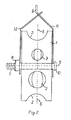
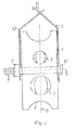
- the present invention comprises a guiding wheel 1 for guiding, mounting and anchoring cables ropes, hoses and wires.
- a cable in this description, it is meant a cable, rope, wire, hose or other elongated object or device to be mounted in a mounting wheel according to the invention.
- the guiding wheel 1 has a rotational shaft 7 with a rotational axis 5 and a peripheral groove 2 for guiding of the cable, and comprising at least one hole 3 running through the wheel 1 perpendicular to the wheel shaft 7 and running as a chord (chordally).
- the guiding wheel 1 is further distinguished in that it is divided via at least one plane 6 running perpendicularly on the rotational axis of the wheel and dividing the one or more holes 3 in at least two, so that the guiding wheel 1 can be divided to expose the chordal hole or holes 3 to be able to arrange the cable in the hole 3 without removing the cable from the peripheral groove 2 in the guiding wheel 1 and without removing parts of the guiding wheel to anchor the cable in the guiding holes 3.
- the one or more holes 3 are formed of two corresponding or mainly corresponding grooves forming a chordal through hole in the wheel when the two halves are combined.
- the purpose of dividing the guiding wheel 1 with a chordal anchoring holes 3 as explained above, is to avoid being obliged to remove a part of the guiding wheel 1 over the holes 3 during installation of the cable, as one has to do in a known solution, where the part of the guiding wheel lying between the guiding groove 2 and the anchoring grooves 3 is removed, to be reassembled after the cable is arranged in the chordal anchoring hole 3.
- the peripheral guiding groove 2 of the guiding wheel 1 can have an even surface or it can be provided with transversally or longitudinally running ridges or grooves to improve the friction between the cable and guiding groove.
- By improving the friction between the cable and guiding wheel it can be avoided that the cable slips in the guiding groove 2 if the guiding wheel rotates to slowly compared to the movement or displacement of the cable, instead of the cable being led forwards as the guiding wheel rotates about the shaft 7. This can as an example be relevant when it is raining, as the guiding wheel 1 can become wet.
- By preventing the cable from slipping in the guiding groove 2 it can also be avoided that a possible insulation of the cable is damaged during pulling of the cable.
- Rotation of the guiding wheel 1 about the shaft 7 can also be eased by providing the guiding wheel or shaft with a slide bearing, roller bearing, ball bearing or the like (not shown). However, due to the production costs for the guiding wheel according to the invention, it will be preferred to make the guiding wheel according to the invention without such bearing.
- the running wheel 1 is opened when one half of the wheel is displaced or shifted on the shaft 7 of the wheel 1, thereby forming a gap between the two halves rendering the grooves forming the hole 3 accessible.
- the cable passing over the wheel 1 is then let down in the now divided hole 3, where after the displaced half of the wheel is shifted back in position to rest towards the first guiding wheel half to clamp the cable in the relevant chordal hole 3.
- the guiding wheel halves are then clamped together by tightening the wheel halves towards each other by means of screwing at least one nut 8 on the shaft 7.
- a method for mounting with a mounting wheel according to the invention as explained above can be implemented in shorter time than what is possible with guiding wheels according to prior art, while maintaining the advantage of the chordal holes.
- the contact surface for the cable through the holes 3 is large and gentle to the wire.
- the cable could also be mounted by leading it directly through the relevant guiding hole 3 of the guiding wheel 1.
- This is however a cumbersome and time consuming mounting method which also makes it difficult to clamp the cable in the relevant guiding hole.
- the guiding hole 3 could be sufficiently big to make the threading simple, but the cable would then have a sufficiently small diameter to easily pass through the guiding hole 3 precluding clamping of the cable in the hole).
- the one or more guiding holes 3 are constructed with adapted diameters to the relevant cable diameters (that is, with a somewhat smaller diameter - in size range 0,5-5 mm smaller- than the diameter of the cable).
- the guiding holes 3 can have an elliptical shape, so that the smallest axis of the ellipsis clamp the cable as explained above (in which case the cable will have some deformation in the clamping area, but where the spot load is avoided).
- one or more guiding holes 3 can also be possible to provide one or more guiding holes 3 with a lining that can assist in clamping the cable in the hole 3.
- the guiding holes 3 may be more practical to make the guiding holes 3 with mainly the same diameters as the relevant cables to be clamped.
- “mainly” it is in this connection meant that it can be accepted a difference between diameter of the hole and diameter of cable of ⁇ 1%. Consequently and as an example, it can be used a cable of 9,9-10,1 mm for an anchoring hole of 10 mm, formed as a circular hole, where the diameter is "mainly" the same as the diameter of the cable.
- the diameter of the guiding holes 3 (if the guiding wheel 1 is provided with more than one guiding hole 3) can be made different from each other so that the guiding wheel can be used for leading and attachment of cables with different diameters.
- the diameter of the anchoring holes 3 can be the same.
- the guiding wheel 1 To open the guiding wheel 1 according to the invention, it is preferred that this is done by loosening the nut 8, so that one half of the guiding wheel can be shifted along the shaft 7 to form a space between the guiding wheel halves.
- This enables the cable (not shown) to slip down between the wheel halves and be attached in the chordal anchoring hole 3 which is designed to fit the cable diameter.
- the cable When the cable is arranged in the anchoring hole 3, the removed or displaced guiding wheel half is brought back to abutment or approaching the fixed guiding wheel half and the nut 8 is tightened to attach the cable in the anchoring hole 3.
- the guiding wheel according to the invention can be provided with a tool set comprising a screw and attachment tool 9,12.
- This screw and attachment tool 9,12 is arranged on the shaft 7 of the guiding wheel 1 and an embodiment of it is shown on fig. 4 .
- the tool 9,12 is formed of a spanner 9 with an opening 11 enabling the tool to fit over the attachment nut 8 for the guiding wheel 1.
- the shaft 7 can, for example, be made of a bolt 10.
- a suitable material such as rigid plastic or metal, preferably nylon or aluminium.
- Fig. 5 shows a perspective view of a further embodiment of the invention.
- the guiding wheel 1 is formed by two corresponding mirrored halves 14.
- the halves are provided with two grooves 13 of different shape and diameter in such a way that the grooves 13 of each half 14 will combine with the grooves of the other half to form a chordal hole in the combined wheel 1.
- the halves are also provided with recess 15 on the circumference forming one half each of the peripheral groove 2.
- the surface of the recesses is provided with transversal ridges 16. The ridges are arranged concurrent on the halves forming the wheel.
- a bolt 10 is provided as a shaft through the rotational axis of the wheel, as explained above.
- a nut 8 and a washer 18 is holding the two halves sufficiently close to each other to form a peripheral groove 2 that is able to hold the cable passing over the wheel. However, the halves are not clamped together during pulling of the cable over the wheel. The two halves will to some extent rotate independently of each other.
- the two halves When the cable is in its final position and is ready to be clamped in the mounting wheel, the two halves should be in a position where the corresponding grooves 13 form the predefined chordal holes.
- an recess 19 can be provided on each half 14 in such a way, that when the two halves are arranged symmetrical to each other forming the predefined holes, the recesses are situated symmetrically to each other on the wheel.
- the wheel 1 is held in a screw/attachment tool 9, 12.
- the screw/attachment tool comprises a spanner 9 and a suspension member 12.
- the spanner 9 is formed as an elongated plate element provided with an opening 11 and a screw hole 22.
- the spanner is formed so that the opening 11 can be placed over the nut 8 on the bolt 10 and a screw 23 can be placed in the hole 22 in such a way that it locks the spanner 9 and suspension member 12 in relation to each other.
- the suspension member 12 is formed as an elongated plate element. It is also provided with a hole (not shown) for placing it on the bolt 10, on the other side of the wheel, compared to the spanner 9 and a hole for the screw 23.
- the suspension member 12 is provided with a further suspension organ 24.
- the suspension organ 24 is provided to attach the guiding wheel 1 according to the invention to a pole, building or other surface where the cable is passing and on which the cable is to be mounted.
- the suspension organ 24 is formed as an extension of the elongated plate element that is provided with a hole 25.
- the pole, building or the like where the cable is to be attached is preferably provided with a swing hook or other suitable anchoring member.
- the hole 25 of the suspension organ 24 is then coupled to the anchoring member so that the guiding wheel can rotate to some extent while being attached to the pole, building or other surface.
- the elongated plate elements of the spanner 9 and suspension member 12 of the present embodiment are formed with two mainly flat end sections being connected by a mainly flat middle section.
- the middle section of the plate elements is arranged in an angle to the two end sections. In this way, the first end sections of the spanner 9 and suspension member 12 pass over one side of the guiding wheel 1, the angled middle sections lead the two plate elements towards each other and the second end sections of the two plate elements are placed against each other with the holes 22 over each other so that a screw 23 can be entered and attached to the elements.
- the suspension organ 24 projects from the suspension member to provide an easy attachment means for the guiding wheel.
- Examples of choices of material for the guiding wheel according to the invention are metal, composite plastic or fibre reinforced composite plastic.
- the guiding wheel has in this example a diameter of 20 cm, with a thickness of 6 cm and an outer even guiding groove 2 with a diameter of 3 cm.
- the chordal holes 3 have different diameters, where the biggest has a diameter of 2.5 cm and the smallest has a diameter of 1.5 cm.
- This guiding wheel is divided perpendicularly to the axis of the wheel and in the middle of the guiding groove 2.
- chordal anchoring holes 3 are here lined with rubber on the inside at a maximum thickness of 0.5 cm.
Landscapes
- Electric Cable Installation (AREA)
- Supports For Pipes And Cables (AREA)
- Insertion, Bundling And Securing Of Wires For Electric Apparatuses (AREA)
- Installation Of Indoor Wiring (AREA)
- Multi-Conductor Connections (AREA)
Applications Claiming Priority (1)
| Application Number | Priority Date | Filing Date | Title |
|---|---|---|---|
| NO20101683A NO332417B1 (no) | 2010-12-01 | 2010-12-01 | Hjul for toppklemme til montering av ledninger og kabler |
Publications (3)
| Publication Number | Publication Date |
|---|---|
| EP2461441A2 true EP2461441A2 (de) | 2012-06-06 |
| EP2461441A3 EP2461441A3 (de) | 2013-09-18 |
| EP2461441B1 EP2461441B1 (de) | 2015-04-08 |
Family
ID=45217335
Family Applications (1)
| Application Number | Title | Priority Date | Filing Date |
|---|---|---|---|
| EP20110191470 Active EP2461441B1 (de) | 2010-12-01 | 2011-12-01 | Rad zur Verlegung von Kabel |
Country Status (2)
| Country | Link |
|---|---|
| EP (1) | EP2461441B1 (de) |
| NO (1) | NO332417B1 (de) |
Cited By (4)
| Publication number | Priority date | Publication date | Assignee | Title |
|---|---|---|---|---|
| CN104300429A (zh) * | 2014-10-19 | 2015-01-21 | 国家电网公司 | 转盘切割式输电线路悬挂物清除装置 |
| CN107769086A (zh) * | 2017-12-18 | 2018-03-06 | 国网河南省电力公司洛阳供电公司 | 一种电网专用绳索过线器 |
| US10689834B2 (en) | 2017-03-06 | 2020-06-23 | Bingham & Taylor Corp. | Meter pit and method of manufacturing the same |
| CN118174195A (zh) * | 2024-05-14 | 2024-06-11 | 山东盛都节能科技有限公司 | 一种粗电缆桥架敷设步进牵引器 |
Citations (3)
| Publication number | Priority date | Publication date | Assignee | Title |
|---|---|---|---|---|
| US2188715A (en) | 1938-08-05 | 1940-01-30 | Cleveland B Ingram | Wire stringing block |
| US3622689A (en) | 1970-03-13 | 1971-11-23 | James R Sparks | Locking insulator |
| NO301679B1 (no) | 1996-03-14 | 1997-11-24 | Edmund Stenslie | Anordning for utkjöring/fastklemming/avlastning av luftgående kabler |
Family Cites Families (2)
| Publication number | Priority date | Publication date | Assignee | Title |
|---|---|---|---|---|
| JPS5845446Y2 (ja) * | 1980-11-18 | 1983-10-15 | 昭和電線電纜株式会社 | 架線用金車 |
| JP2959741B2 (ja) * | 1993-03-18 | 1999-10-06 | 株式会社安田製作所 | 巻上げ式滑車 |
-
2010
- 2010-12-01 NO NO20101683A patent/NO332417B1/no unknown
-
2011
- 2011-12-01 EP EP20110191470 patent/EP2461441B1/de active Active
Patent Citations (3)
| Publication number | Priority date | Publication date | Assignee | Title |
|---|---|---|---|---|
| US2188715A (en) | 1938-08-05 | 1940-01-30 | Cleveland B Ingram | Wire stringing block |
| US3622689A (en) | 1970-03-13 | 1971-11-23 | James R Sparks | Locking insulator |
| NO301679B1 (no) | 1996-03-14 | 1997-11-24 | Edmund Stenslie | Anordning for utkjöring/fastklemming/avlastning av luftgående kabler |
Cited By (7)
| Publication number | Priority date | Publication date | Assignee | Title |
|---|---|---|---|---|
| CN104300429A (zh) * | 2014-10-19 | 2015-01-21 | 国家电网公司 | 转盘切割式输电线路悬挂物清除装置 |
| CN104300429B (zh) * | 2014-10-19 | 2017-01-25 | 国家电网公司 | 转盘切割式输电线路悬挂物清除装置 |
| US10689834B2 (en) | 2017-03-06 | 2020-06-23 | Bingham & Taylor Corp. | Meter pit and method of manufacturing the same |
| US12188211B2 (en) | 2017-03-06 | 2025-01-07 | Bingham & Taylor Corp. | Meter pit and method of manufacturing the same |
| CN107769086A (zh) * | 2017-12-18 | 2018-03-06 | 国网河南省电力公司洛阳供电公司 | 一种电网专用绳索过线器 |
| CN107769086B (zh) * | 2017-12-18 | 2023-10-24 | 国网河南省电力公司洛阳供电公司 | 一种电网专用绳索过线器 |
| CN118174195A (zh) * | 2024-05-14 | 2024-06-11 | 山东盛都节能科技有限公司 | 一种粗电缆桥架敷设步进牵引器 |
Also Published As
| Publication number | Publication date |
|---|---|
| NO20101683A1 (no) | 2012-06-04 |
| EP2461441B1 (de) | 2015-04-08 |
| EP2461441A3 (de) | 2013-09-18 |
| NO332417B1 (no) | 2012-09-17 |
Similar Documents
| Publication | Publication Date | Title |
|---|---|---|
| US8500073B2 (en) | Hinged bushing suspension clamp and method for using said clamp | |
| US9732780B2 (en) | Cantilever assembly | |
| EP2461441B1 (de) | Rad zur Verlegung von Kabel | |
| CN202127205U (zh) | 电缆快速固定卡具 | |
| US8820715B2 (en) | Wire stringing angle clamp | |
| CN106567331B (zh) | 一种可调式钢丝拉索锚具 | |
| CN110468710B (zh) | 一种大倾角空间斜主缆索夹的抗滑移装置及安装方法 | |
| FI3388697T4 (fi) | Leikkautuva kiinnityspultti ja menetelmä sähköjohtojen kiinnittämiseen sekä ulkonemattoman leikkautuvan kiinnittimen käsittävä sähköliitin | |
| CN104538887A (zh) | 一种避雷线提升转换器 | |
| JP2014143993A (ja) | 鳥害防止具 | |
| US20090283289A1 (en) | Wedge retention assembly | |
| JP2008067515A (ja) | 電線用スペーサおよび電線架線構造 | |
| CA2779770C (en) | Cord gripping mechanism and method | |
| US20040040123A1 (en) | Wire stop for multi-strand steel cable | |
| US20120132762A1 (en) | Wedge retention assembly | |
| US20160172834A1 (en) | Releasable Messenger Clamp | |
| CN205377194U (zh) | 自锁电缆固定装置 | |
| US9455555B2 (en) | Wire stringing angle clamp | |
| CN112993862A (zh) | 一种用于电力施工的紧线装置 | |
| CN107465146B (zh) | 用于线路导线紧线的组合紧线工具 | |
| JP2016141570A (ja) | ロープリールのロープ端末繋ぎ止め装置 | |
| CN205069909U (zh) | 电缆线夹及紧固系统 | |
| CN110233457A (zh) | 一种导线牵引装置 | |
| CN211743998U (zh) | 防滑移防振锤 | |
| KR200487311Y1 (ko) | 와이어 고정장치 |
Legal Events
| Date | Code | Title | Description |
|---|---|---|---|
| PUAI | Public reference made under article 153(3) epc to a published international application that has entered the european phase |
Free format text: ORIGINAL CODE: 0009012 |
|
| AK | Designated contracting states |
Kind code of ref document: A2 Designated state(s): AL AT BE BG CH CY CZ DE DK EE ES FI FR GB GR HR HU IE IS IT LI LT LU LV MC MK MT NL NO PL PT RO RS SE SI SK SM TR |
|
| AX | Request for extension of the european patent |
Extension state: BA ME |
|
| PUAL | Search report despatched |
Free format text: ORIGINAL CODE: 0009013 |
|
| AK | Designated contracting states |
Kind code of ref document: A3 Designated state(s): AL AT BE BG CH CY CZ DE DK EE ES FI FR GB GR HR HU IE IS IT LI LT LU LV MC MK MT NL NO PL PT RO RS SE SI SK SM TR |
|
| AX | Request for extension of the european patent |
Extension state: BA ME |
|
| RIC1 | Information provided on ipc code assigned before grant |
Ipc: H02G 1/04 20060101AFI20130809BHEP |
|
| 17P | Request for examination filed |
Effective date: 20140225 |
|
| RBV | Designated contracting states (corrected) |
Designated state(s): AL AT BE BG CH CY CZ DE DK EE ES FI FR GB GR HR HU IE IS IT LI LT LU LV MC MK MT NL NO PL PT RO RS SE SI SK SM TR |
|
| GRAP | Despatch of communication of intention to grant a patent |
Free format text: ORIGINAL CODE: EPIDOSNIGR1 |
|
| INTG | Intention to grant announced |
Effective date: 20140625 |
|
| GRAP | Despatch of communication of intention to grant a patent |
Free format text: ORIGINAL CODE: EPIDOSNIGR1 |
|
| INTG | Intention to grant announced |
Effective date: 20141106 |
|
| GRAS | Grant fee paid |
Free format text: ORIGINAL CODE: EPIDOSNIGR3 |
|
| GRAA | (expected) grant |
Free format text: ORIGINAL CODE: 0009210 |
|
| AK | Designated contracting states |
Kind code of ref document: B1 Designated state(s): AL AT BE BG CH CY CZ DE DK EE ES FI FR GB GR HR HU IE IS IT LI LT LU LV MC MK MT NL NO PL PT RO RS SE SI SK SM TR |
|
| AX | Request for extension of the european patent |
Extension state: BA ME |
|
| REG | Reference to a national code |
Ref country code: GB Ref legal event code: FG4D |
|
| REG | Reference to a national code |
Ref country code: CH Ref legal event code: EP |
|
| REG | Reference to a national code |
Ref country code: SE Ref legal event code: TRGR |
|
| REG | Reference to a national code |
Ref country code: IE Ref legal event code: FG4D |
|
| REG | Reference to a national code |
Ref country code: AT Ref legal event code: REF Ref document number: 721195 Country of ref document: AT Kind code of ref document: T Effective date: 20150515 |
|
| REG | Reference to a national code |
Ref country code: DE Ref legal event code: R096 Ref document number: 602011015399 Country of ref document: DE Effective date: 20150521 |
|
| REG | Reference to a national code |
Ref country code: AT Ref legal event code: MK05 Ref document number: 721195 Country of ref document: AT Kind code of ref document: T Effective date: 20150408 |
|
| REG | Reference to a national code |
Ref country code: NL Ref legal event code: VDEP Effective date: 20150408 |
|
| REG | Reference to a national code |
Ref country code: LT Ref legal event code: MG4D |
|
| PG25 | Lapsed in a contracting state [announced via postgrant information from national office to epo] |
Ref country code: NL Free format text: LAPSE BECAUSE OF FAILURE TO SUBMIT A TRANSLATION OF THE DESCRIPTION OR TO PAY THE FEE WITHIN THE PRESCRIBED TIME-LIMIT Effective date: 20150408 |
|
| PG25 | Lapsed in a contracting state [announced via postgrant information from national office to epo] |
Ref country code: LT Free format text: LAPSE BECAUSE OF FAILURE TO SUBMIT A TRANSLATION OF THE DESCRIPTION OR TO PAY THE FEE WITHIN THE PRESCRIBED TIME-LIMIT Effective date: 20150408 Ref country code: NO Free format text: LAPSE BECAUSE OF FAILURE TO SUBMIT A TRANSLATION OF THE DESCRIPTION OR TO PAY THE FEE WITHIN THE PRESCRIBED TIME-LIMIT Effective date: 20150708 Ref country code: FI Free format text: LAPSE BECAUSE OF FAILURE TO SUBMIT A TRANSLATION OF THE DESCRIPTION OR TO PAY THE FEE WITHIN THE PRESCRIBED TIME-LIMIT Effective date: 20150408 Ref country code: PT Free format text: LAPSE BECAUSE OF FAILURE TO SUBMIT A TRANSLATION OF THE DESCRIPTION OR TO PAY THE FEE WITHIN THE PRESCRIBED TIME-LIMIT Effective date: 20150810 Ref country code: HR Free format text: LAPSE BECAUSE OF FAILURE TO SUBMIT A TRANSLATION OF THE DESCRIPTION OR TO PAY THE FEE WITHIN THE PRESCRIBED TIME-LIMIT Effective date: 20150408 Ref country code: ES Free format text: LAPSE BECAUSE OF FAILURE TO SUBMIT A TRANSLATION OF THE DESCRIPTION OR TO PAY THE FEE WITHIN THE PRESCRIBED TIME-LIMIT Effective date: 20150408 |
|
| PG25 | Lapsed in a contracting state [announced via postgrant information from national office to epo] |
Ref country code: GR Free format text: LAPSE BECAUSE OF FAILURE TO SUBMIT A TRANSLATION OF THE DESCRIPTION OR TO PAY THE FEE WITHIN THE PRESCRIBED TIME-LIMIT Effective date: 20150709 Ref country code: IS Free format text: LAPSE BECAUSE OF FAILURE TO SUBMIT A TRANSLATION OF THE DESCRIPTION OR TO PAY THE FEE WITHIN THE PRESCRIBED TIME-LIMIT Effective date: 20150808 Ref country code: AT Free format text: LAPSE BECAUSE OF FAILURE TO SUBMIT A TRANSLATION OF THE DESCRIPTION OR TO PAY THE FEE WITHIN THE PRESCRIBED TIME-LIMIT Effective date: 20150408 Ref country code: RS Free format text: LAPSE BECAUSE OF FAILURE TO SUBMIT A TRANSLATION OF THE DESCRIPTION OR TO PAY THE FEE WITHIN THE PRESCRIBED TIME-LIMIT Effective date: 20150408 Ref country code: LV Free format text: LAPSE BECAUSE OF FAILURE TO SUBMIT A TRANSLATION OF THE DESCRIPTION OR TO PAY THE FEE WITHIN THE PRESCRIBED TIME-LIMIT Effective date: 20150408 |
|
| REG | Reference to a national code |
Ref country code: DE Ref legal event code: R097 Ref document number: 602011015399 Country of ref document: DE |
|
| PG25 | Lapsed in a contracting state [announced via postgrant information from national office to epo] |
Ref country code: EE Free format text: LAPSE BECAUSE OF FAILURE TO SUBMIT A TRANSLATION OF THE DESCRIPTION OR TO PAY THE FEE WITHIN THE PRESCRIBED TIME-LIMIT Effective date: 20150408 Ref country code: DK Free format text: LAPSE BECAUSE OF FAILURE TO SUBMIT A TRANSLATION OF THE DESCRIPTION OR TO PAY THE FEE WITHIN THE PRESCRIBED TIME-LIMIT Effective date: 20150408 |
|
| PLBE | No opposition filed within time limit |
Free format text: ORIGINAL CODE: 0009261 |
|
| STAA | Information on the status of an ep patent application or granted ep patent |
Free format text: STATUS: NO OPPOSITION FILED WITHIN TIME LIMIT |
|
| PG25 | Lapsed in a contracting state [announced via postgrant information from national office to epo] |
Ref country code: PL Free format text: LAPSE BECAUSE OF FAILURE TO SUBMIT A TRANSLATION OF THE DESCRIPTION OR TO PAY THE FEE WITHIN THE PRESCRIBED TIME-LIMIT Effective date: 20150408 Ref country code: SK Free format text: LAPSE BECAUSE OF FAILURE TO SUBMIT A TRANSLATION OF THE DESCRIPTION OR TO PAY THE FEE WITHIN THE PRESCRIBED TIME-LIMIT Effective date: 20150408 Ref country code: RO Free format text: LAPSE BECAUSE OF NON-PAYMENT OF DUE FEES Effective date: 20150408 Ref country code: CZ Free format text: LAPSE BECAUSE OF FAILURE TO SUBMIT A TRANSLATION OF THE DESCRIPTION OR TO PAY THE FEE WITHIN THE PRESCRIBED TIME-LIMIT Effective date: 20150408 |
|
| 26N | No opposition filed |
Effective date: 20160111 |
|
| PG25 | Lapsed in a contracting state [announced via postgrant information from national office to epo] |
Ref country code: IT Free format text: LAPSE BECAUSE OF FAILURE TO SUBMIT A TRANSLATION OF THE DESCRIPTION OR TO PAY THE FEE WITHIN THE PRESCRIBED TIME-LIMIT Effective date: 20150408 |
|
| PG25 | Lapsed in a contracting state [announced via postgrant information from national office to epo] |
Ref country code: SI Free format text: LAPSE BECAUSE OF FAILURE TO SUBMIT A TRANSLATION OF THE DESCRIPTION OR TO PAY THE FEE WITHIN THE PRESCRIBED TIME-LIMIT Effective date: 20150408 Ref country code: BE Free format text: LAPSE BECAUSE OF NON-PAYMENT OF DUE FEES Effective date: 20151231 |
|
| REG | Reference to a national code |
Ref country code: DE Ref legal event code: R119 Ref document number: 602011015399 Country of ref document: DE |
|
| PG25 | Lapsed in a contracting state [announced via postgrant information from national office to epo] |
Ref country code: LU Free format text: LAPSE BECAUSE OF FAILURE TO SUBMIT A TRANSLATION OF THE DESCRIPTION OR TO PAY THE FEE WITHIN THE PRESCRIBED TIME-LIMIT Effective date: 20151201 Ref country code: MC Free format text: LAPSE BECAUSE OF FAILURE TO SUBMIT A TRANSLATION OF THE DESCRIPTION OR TO PAY THE FEE WITHIN THE PRESCRIBED TIME-LIMIT Effective date: 20150408 |
|
| REG | Reference to a national code |
Ref country code: CH Ref legal event code: PL |
|
| GBPC | Gb: european patent ceased through non-payment of renewal fee |
Effective date: 20151201 |
|
| PG25 | Lapsed in a contracting state [announced via postgrant information from national office to epo] |
Ref country code: BE Free format text: LAPSE BECAUSE OF FAILURE TO SUBMIT A TRANSLATION OF THE DESCRIPTION OR TO PAY THE FEE WITHIN THE PRESCRIBED TIME-LIMIT Effective date: 20150408 |
|
| REG | Reference to a national code |
Ref country code: IE Ref legal event code: MM4A |
|
| REG | Reference to a national code |
Ref country code: FR Ref legal event code: ST Effective date: 20160831 |
|
| PG25 | Lapsed in a contracting state [announced via postgrant information from national office to epo] |
Ref country code: CH Free format text: LAPSE BECAUSE OF NON-PAYMENT OF DUE FEES Effective date: 20151231 Ref country code: LI Free format text: LAPSE BECAUSE OF NON-PAYMENT OF DUE FEES Effective date: 20151231 Ref country code: GB Free format text: LAPSE BECAUSE OF NON-PAYMENT OF DUE FEES Effective date: 20151201 Ref country code: DE Free format text: LAPSE BECAUSE OF NON-PAYMENT OF DUE FEES Effective date: 20160701 Ref country code: IE Free format text: LAPSE BECAUSE OF NON-PAYMENT OF DUE FEES Effective date: 20151201 |
|
| PG25 | Lapsed in a contracting state [announced via postgrant information from national office to epo] |
Ref country code: FR Free format text: LAPSE BECAUSE OF NON-PAYMENT OF DUE FEES Effective date: 20151231 |
|
| PG25 | Lapsed in a contracting state [announced via postgrant information from national office to epo] |
Ref country code: BG Free format text: LAPSE BECAUSE OF FAILURE TO SUBMIT A TRANSLATION OF THE DESCRIPTION OR TO PAY THE FEE WITHIN THE PRESCRIBED TIME-LIMIT Effective date: 20150408 Ref country code: HU Free format text: LAPSE BECAUSE OF FAILURE TO SUBMIT A TRANSLATION OF THE DESCRIPTION OR TO PAY THE FEE WITHIN THE PRESCRIBED TIME-LIMIT; INVALID AB INITIO Effective date: 20111201 Ref country code: SM Free format text: LAPSE BECAUSE OF FAILURE TO SUBMIT A TRANSLATION OF THE DESCRIPTION OR TO PAY THE FEE WITHIN THE PRESCRIBED TIME-LIMIT Effective date: 20150408 |
|
| PG25 | Lapsed in a contracting state [announced via postgrant information from national office to epo] |
Ref country code: CY Free format text: LAPSE BECAUSE OF FAILURE TO SUBMIT A TRANSLATION OF THE DESCRIPTION OR TO PAY THE FEE WITHIN THE PRESCRIBED TIME-LIMIT Effective date: 20150408 |
|
| PG25 | Lapsed in a contracting state [announced via postgrant information from national office to epo] |
Ref country code: MT Free format text: LAPSE BECAUSE OF FAILURE TO SUBMIT A TRANSLATION OF THE DESCRIPTION OR TO PAY THE FEE WITHIN THE PRESCRIBED TIME-LIMIT Effective date: 20150408 Ref country code: TR Free format text: LAPSE BECAUSE OF FAILURE TO SUBMIT A TRANSLATION OF THE DESCRIPTION OR TO PAY THE FEE WITHIN THE PRESCRIBED TIME-LIMIT Effective date: 20150408 |
|
| PG25 | Lapsed in a contracting state [announced via postgrant information from national office to epo] |
Ref country code: MK Free format text: LAPSE BECAUSE OF FAILURE TO SUBMIT A TRANSLATION OF THE DESCRIPTION OR TO PAY THE FEE WITHIN THE PRESCRIBED TIME-LIMIT Effective date: 20150408 |
|
| PG25 | Lapsed in a contracting state [announced via postgrant information from national office to epo] |
Ref country code: AL Free format text: LAPSE BECAUSE OF FAILURE TO SUBMIT A TRANSLATION OF THE DESCRIPTION OR TO PAY THE FEE WITHIN THE PRESCRIBED TIME-LIMIT Effective date: 20150408 |
|
| PGFP | Annual fee paid to national office [announced via postgrant information from national office to epo] |
Ref country code: SE Payment date: 20251216 Year of fee payment: 15 |