EP2462010B1 - Wischblatt in flachbalkenbauweise - Google Patents
Wischblatt in flachbalkenbauweise Download PDFInfo
- Publication number
- EP2462010B1 EP2462010B1 EP10726037.4A EP10726037A EP2462010B1 EP 2462010 B1 EP2462010 B1 EP 2462010B1 EP 10726037 A EP10726037 A EP 10726037A EP 2462010 B1 EP2462010 B1 EP 2462010B1
- Authority
- EP
- European Patent Office
- Prior art keywords
- wiper blade
- longitudinal
- spoiler
- strip
- longitudinal channel
- Prior art date
- Legal status (The legal status is an assumption and is not a legal conclusion. Google has not performed a legal analysis and makes no representation as to the accuracy of the status listed.)
- Active
Links
Images
Classifications
-
- B—PERFORMING OPERATIONS; TRANSPORTING
- B60—VEHICLES IN GENERAL
- B60S—SERVICING, CLEANING, REPAIRING, SUPPORTING, LIFTING, OR MANOEUVRING OF VEHICLES, NOT OTHERWISE PROVIDED FOR
- B60S1/00—Cleaning of vehicles
- B60S1/02—Cleaning windscreens, windows or optical devices
- B60S1/04—Wipers or the like, e.g. scrapers
- B60S1/32—Wipers or the like, e.g. scrapers characterised by constructional features of wiper blade arms or blades
- B60S1/38—Wiper blades
- B60S1/3848—Flat-type wiper blade, i.e. without harness
- B60S1/3874—Flat-type wiper blade, i.e. without harness with a reinforcing vertebra
- B60S1/3875—Flat-type wiper blade, i.e. without harness with a reinforcing vertebra rectangular section
- B60S1/3881—Flat-type wiper blade, i.e. without harness with a reinforcing vertebra rectangular section in additional element, e.g. spoiler
-
- B—PERFORMING OPERATIONS; TRANSPORTING
- B60—VEHICLES IN GENERAL
- B60S—SERVICING, CLEANING, REPAIRING, SUPPORTING, LIFTING, OR MANOEUVRING OF VEHICLES, NOT OTHERWISE PROVIDED FOR
- B60S1/00—Cleaning of vehicles
- B60S1/02—Cleaning windscreens, windows or optical devices
- B60S1/04—Wipers or the like, e.g. scrapers
- B60S1/32—Wipers or the like, e.g. scrapers characterised by constructional features of wiper blade arms or blades
- B60S1/38—Wiper blades
- B60S1/3806—Means, or measures taken, for influencing the aerodynamic quality of the wiper blades
- B60S1/381—Spoilers mounted on the squeegee or on the vertebra
-
- B—PERFORMING OPERATIONS; TRANSPORTING
- B60—VEHICLES IN GENERAL
- B60S—SERVICING, CLEANING, REPAIRING, SUPPORTING, LIFTING, OR MANOEUVRING OF VEHICLES, NOT OTHERWISE PROVIDED FOR
- B60S1/00—Cleaning of vehicles
- B60S1/02—Cleaning windscreens, windows or optical devices
- B60S1/04—Wipers or the like, e.g. scrapers
- B60S1/32—Wipers or the like, e.g. scrapers characterised by constructional features of wiper blade arms or blades
- B60S1/38—Wiper blades
-
- B—PERFORMING OPERATIONS; TRANSPORTING
- B60—VEHICLES IN GENERAL
- B60S—SERVICING, CLEANING, REPAIRING, SUPPORTING, LIFTING, OR MANOEUVRING OF VEHICLES, NOT OTHERWISE PROVIDED FOR
- B60S1/00—Cleaning of vehicles
- B60S1/02—Cleaning windscreens, windows or optical devices
- B60S1/04—Wipers or the like, e.g. scrapers
- B60S1/32—Wipers or the like, e.g. scrapers characterised by constructional features of wiper blade arms or blades
- B60S1/38—Wiper blades
- B60S2001/3827—Wiper blades characterised by the squeegee or blade rubber or wiping element
- B60S2001/3829—Wiper blades characterised by the squeegee or blade rubber or wiping element characterised by the material of the squeegee or coating thereof
Definitions
- the invention is based on a wiper blade in flat bar construction according to the preamble of claim 1.
- His wiper strip has a relatively wide header, in which a longitudinal channel is provided for receiving a cross-sectionally approximately rectangular spring rail.
- the spring rail is comprised together with a part of the head strip of a retaining profile of a spoiler, whose facing free legs engage in lateral longitudinal grooves below the spring rail in the head strip.
- a further longitudinal channel for receiving a second in cross-section also rectangular spring rail is arranged in the spoiler.
- a further longitudinal channel is provided to a longitudinal ridge of the spoiler in the region of an inflow profile, which serves to save material.
- the spoiler longitudinal channel for receiving the second spring rail to the header has a longitudinal gap.
- the spoiler is made in the region of the inflow profile of a softer material than in the region of its holding profile, wherein the separating surface extends below the second spring rail to the head strip.
- EP-A-1627787 discloses the preamble of claim 1.
- the header is free of spring rails.
- the legs of the spoiler can fully engage in longitudinal grooves of the wiper blade head.
- the longitudinal grooves of the head strip consist for receiving the retaining profile of Spoilers forming parts made of a harder material than the wiper lip and / or the Kippsteg. Due to the design of the wiper blade according to the invention, the head strip can be made very narrow, so that the overall result is a very narrow wiper blade, which is not determined in its width by the arranged in the header spring rail, but by the desired flow conditions on the spoiler.
- the necessary design and design of the support elements in the form of spring rails is matched to the exterior design of the spoiler.
- the spring rails adapt to the cross-section of the available inner contour of the longitudinal channels, as far as this is possible taking into account the technical requirements of the spring properties of the spring rails.
- one or more spring rails may expediently be arranged parallel to one another and / or next to one another, of which at least one deviates from the rectangular shape in cross section and follows the inner contour of the associated longitudinal channel on the inflow side in its cross-sectional contour.
- the spoiler profile can be used up to the vicinity of the longitudinal ridge for receiving a spring rail. This results in essentially trapezoidal or triangular cross-sections, the sides of which can also be curved.
- the spaces between the spring rails and the longitudinal channels are filled by sponge rubber or soft rubber.
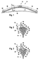
- a wiper blade 10 in a flat-beam construction is constructed from a wiper strip 14, a spoiler 32 and at least one spring rail 46. At the ends of the wiper blade 10 are end caps 58, which limit the relative mobility of the wiper strip 14 of the spring rail 46 and the spoiler 32 in the longitudinal direction relative to each other.
- a connecting element 12 is attached to the wiper blade 10. It is used for articulated connection with a wiper arm, not shown.
- the wiper blade 10 is curved concavely in the unloaded state to a vehicle window 16, so that it bears against the vehicle window 16 at its ends. In the loaded state, the wiper strip 14 is pressed over its entire length with a suitable contact pressure against the vehicle window 16.
- the wiper strip 14 comprises a wiper lip 18, which is connected via a tilting web 20 with a head strip 22. Between the tilting web 20 and the header 22 side support strips 28 are provided which favor the folding of the wiper lip 18 in the reversal positions of the wiper blade 10 during the wiping operation.
- the head strip 22 has lateral longitudinal grooves 24 into which a retaining profile 38 of the spoiler 32 engages.
- a retaining profile 38 of the spoiler 32 engages.
- the longitudinal grooves 24 form between them a web 26.
- the upper side, which faces away from the wiper lip 18, subsequent part of the header 22, is referred to as a back bar 30 and 32 includes the support profile of the spoiler 32.
- the header 22 is suitably made in a Mehrstoffxtrusions vide of a harder material than the rest of the wiper strip 14, namely the wiper lip 18 and the support strips 28. This results between the support section 38 of the spoiler and the header 22 a low friction associated with low wear. In addition, due to the higher strength, the header 22 can be made very narrow.
- the inflow profile 34 adjoining the retaining profile 38 is made of a softer material than the retaining profile 38.
- the spoiler 32 is expediently produced in a multi-material extrusion process.
- the inflow profile 34 has a cross-sectional basic structure, which is aligned with a right-angled triangle, wherein the right angle is on the holding profile 38 side facing. On the opposite side, the spoiler 32 merges into a narrow longitudinal ridge 36.
- the outer surfaces of the inflow profile 34 exposed to the airstream can be shaped concavely or convexly in accordance with the desired flow conditions on the spoiler 32 on the inflow side and / or the outflow side.
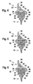
- the inflow profile 34 of the spoiler 32 has at least one first longitudinal channel 44, in which the first spring rail 46 is accommodated. It has expediently a flat, rectangular cross-section.
- first longitudinal channel 44 in the embodiment according to Fig. 2 is closed, is in the embodiment after Fig. 3 the first longitudinal channel 50 open towards the back strip 30, so that the first spring rail 46 can rest on the back strip 30 of the head strip 22.
- second longitudinal channel 48 in each case above the first spring rail 46 toward the longitudinal ridge 36, there is a second longitudinal channel 48, the inner contour of which is aligned with the outer contour of the inflow profile 34.
- the second longitudinal channel 48 may serve in addition to the first longitudinal channel 44, 50 for receiving a further second spring rail 52, 54 or as the only longitudinal channel 44, 50, a spring rail 52, 54 according to the embodiments according to Fig. 4 to Fig. 6 take up.
- the second spring rails 52, 54 as far as the desired and required spring properties of the spring rails 52, 54 permit, at least partially conform to the inner contour of the second longitudinal channel 48.
- the second spring rail 52 has after Fig. 4 a substantially trapezoidal cross-section, while the second spring rail 54 after Fig. 5 and Fig. 6 has a substantially triangular cross-section.
- the intermediate space between the second spring rail 46, 52, 54 and the longitudinal channels 44, 48 with a sponge rubber or soft rubber fill.
- a sponge rubber or soft rubber fill is expedient.
- the sponge rubber or soft rubber 56 allows the required slight longitudinal displacement at different radii of curvature, but at the same time prevents noise caused by contacts with the longitudinal channel walls.
- first and second spring rails 46, 52, 54 and the associated first and second longitudinal channels 44, 48, 50 can be applied to a wiper blade 10 individually or in combination with each other.
Landscapes
- Engineering & Computer Science (AREA)
- Mechanical Engineering (AREA)
- Physics & Mathematics (AREA)
- Fluid Mechanics (AREA)
- Quality & Reliability (AREA)
- Seal Device For Vehicle (AREA)
- Cleaning Implements For Floors, Carpets, Furniture, Walls, And The Like (AREA)
- Extrusion Moulding Of Plastics Or The Like (AREA)
- Nozzles For Electric Vacuum Cleaners (AREA)
- Bridges Or Land Bridges (AREA)
- Springs (AREA)
Description
- Die Erfindung geht von einem Wischblatt in Flachbalkenbauweise nach dem Oberbegriff des Anspruchs 1 aus.
- Aus der
DE 10 2006 020 524 A1 ist ein gattungsgemäßes Wischblatt nach dem Oberbegriff von Anspruch 1 bekannt. Seine Wischleiste besitzt eine relativ breite Kopfleiste, in der ein Längskanal zur Aufnahme einer im Querschnitt etwa rechteckigen Federschiene vorgesehen ist. Die Federschiene wird zusammen mit einem Teil der Kopfleiste von einem Halteprofil eines Spoilers umfasst, dessen einander zugewandte freie Schenkel in seitliche Längsnuten unterhalb der Federschiene in die Kopfleiste eingreifen. Auf der einer Fahrzeugscheibe abgewandten Seite der Federschiene ist im Spoiler ein weiterer Längskanal für die Aufnahme einer zweiten im Querschnitt ebenfalls rechteckigen Federschiene angeordnet. Darüber ist zu einem Längsgrat des Spoilers im Bereich eines Anströmprofils ein weiterer Längskanal vorgesehen, der zur Materialeinsparung dient. Um die Montage zu erleichtern, besitzt der im Spoiler vorgesehene Längskanal zur Aufnahme der zweiten Federschiene zur Kopfleiste hin einen Längsspalt. Der Spoiler ist im Bereich des Anströmprofils aus einem weicheren Material hergestellt, als im Bereich seines Halteprofils, wobei die Trennfläche unterhalb der zweiten Federschiene zur Kopfleiste hin verläuft. -
EP-A-1627787 offenbart den Oberbegriff des Anspruchs 1. - Nach der Erfindung ist die Kopfleiste frei von Federschienen. Die Schenkel des Spoilers können vollständig in Längsnuten des Wischerleistenkopfes eingreifen. Die Längsnuten der Kopfleiste bestehen für die Aufnahme des Halteprofils des Spoilers bildenden Teile aus einem härteren Werkstoff als die Wischlippe und/oder der Kippsteg. Durch die erfindungsgemäße Gestaltung des Wischblatts kann die Kopfleiste sehr schmal gestaltet werden, sodass sich insgesamt ein sehr schmales Wischblatt ergibt, das in seiner Breite nicht durch die in der Kopfleiste angeordneten Federschiene, sondern durch die gewünschten Strömungsverhältnisse am Spoiler bestimmt wird. Die notwendige Gestaltung und Auslegung der Tragelemente in Form von Federschienen ist auf die äußere Gestaltung des Spoilers abgestimmt. Die Federschienen passen sich im Querschnitt der zur Verfügung stehenden Innenkontur der Längskanäle an, soweit dies unter Berücksichtigung der technischen Anforderungen an die Federeigenschaften der Federschienen möglich ist. So können zweckmäßigerweise ein oder mehrere Federschienen parallel übereinander und/oder nebeneinander angeordnet werden, von denen zumindest eine im Querschnitt von der Rechteckform abweicht und auf der Anströmseite in ihrer Querschnittkontur der Innenkontur des zugeordneten Längskanals folgt. Somit kann das Spoilerprofil bis in die Nähe des Längsgrates für die Aufnahme einer Federschiene genutzt werden. Dabei ergeben sich im Wesentlichen trapezförmige oder dreieckige Querschnitte, deren Seiten auch gekrümmt verlaufen können.
- Um die Beweglichkeit der Federschienen in den Längskanälen relativ zum Spoiler zu gewährleisten, ohne dass Geräusche entstehen oder sich die Federschienen verklemmen, ist es zweckmäßig, dass die Zwischenräume zwischen den Federschienen und den Längskanälen durch Moosgummi oder Weichgummi ausgefüllt werden.
- Weitere Vorteile ergeben sich aus der folgenden Zeichnungsbeschreibung. In der Zeichnung sind Ausführungsbeispiele der Erfindung dargestellt. Die Zeichnung, die Beschreibung und die Ansprüche enthalten zahlreiche Merkmale in Kombination. Der Fachmann wird die Merkmale zweckmäßigerweise auch einzeln betrachten und zu sinnvollen weiteren Kombinationen zusammenfassen.
- Es zeigen:
-
Fig. 1 eine Seitenansicht eines erfindungsgemäßen Wischblatts, das sich ohne Belastung an einer Fahrzeugscheibe abstützt, -
Fig. 2 einen Querschnitt entsprechend der Linie II-II inFig. 1 und Fig. 3 bisFig. 6 Varianten zuFig. 2 . - Ein Wischblatt 10 in Flachbalkenbauweise ist aus einer Wischleiste 14, einem Spoiler 32 und mindestens einer Federschiene 46 aufgebaut. An den Enden des Wischblatts 10 befinden sich Endkappen 58, die die relative Beweglichkeit der Wischleiste 14 der Federschiene 46 und des Spoilers 32 in Längsrichtung relativ zueinander begrenzen. Im mittleren Bereich des Wischblatts 10 ist ein Anschlusselement 12 am Wischblatt 10 befestigt. Es dient zur gelenkigen Verbindung mit einem nicht näher dargestellten Wischarm. Das Wischblatt 10 ist in unbelastetem Zustand zu einer Fahrzeugscheibe 16 hin konkav gekrümmt, sodass es an seinen Enden an der Fahrzeugscheibe 16 anliegt. Im belasteten Zustand wird die Wischleiste 14 auf ihrer gesamten Länge mit einem geeigneten Anpressdruck an die Fahrzeugscheibe 16 angepresst.
- Die Wischleiste 14 umfasst eine Wischlippe 18, die über einen Kippsteg 20 mit einer Kopfleiste 22 verbunden ist. Zwischen dem Kippsteg 20 und der Kopfleiste 22 sind seitliche Stützleisten 28 vorgesehen, die das Umlegen der Wischlippe 18 in den Umkehrpositionen des Wischblatts 10 während des Wischbetriebs begünstigen.
- Die Kopfleiste 22 besitzt seitliche Längsnuten 24, in die ein Halteprofil 38 des Spoilers 32 eingreift. Hierzu dienen L-förmige Schenkel 40 an den Längsseiten des Halteprofils 38, die jeweils mit einem Schenkel mit einem Anströmprofil 34 des Spoilers 32 verbunden sind, während die freien Schenkel 42 nach innen gerichtet sind und in die Längsnuten 24 eingreifen. Die Längsnuten 24 bilden zwischen sich einen Steg 26. Der zur oberen Seite, die der Wischlippe 18 abgewandt ist, anschließende Teil der Kopfleiste 22, wird als Rückenleiste 30 bezeichnet und von dem Halteprofil 38 des Spoilers 32 umfasst.
- Die Kopfleiste 22 ist zweckmäßigerweise in einem Mehrstoffextrusionsverfahren aus einem härteren Werkstoff hergestellt als die übrige Wischleiste 14, nämlich die Wischlippe 18 und die Stützleisten 28. Dadurch ergibt sich zwischen dem Halteprofil 38 des Spoilers und der Kopfleiste 22 eine geringe Reibung verbunden mit einem geringen Verschleiß. Außerdem kann auf Grund der höheren Festigkeit die Kopfleiste 22 sehr schmal ausgebildet werden.
- Das sich an das Halteprofil 38 anschließende Anströmprofil 34 ist aus einem weicheren Werkstoff hergestellt, als das Halteprofil 38. Zweckmäßigerweise wird der Spoiler 32 in einem Mehrstoffextrusionsverfahren hergestellt. Das Anströmprofil 34 besitzt eine Querschnittgrundstruktur, die einem rechtwinkligen Dreieck angeglichen ist, wobei der rechte Winkel an der dem Halteprofil 38 zugewandten Seite liegt. An der gegenüberliegenden Seite läuft der Spoiler 32 zu einem schmalen Längsgrat 36 zusammen. Die dem Fahrtwind ausgesetzten Außenflächen des Anströmprofils 34 können entsprechend den gewünschten Strömungsverhältnissen am Spoiler 32 auf der Anströmseite und/oder der Abströmseite konkav oder konvex geformt sein.
- Das Anströmprofil 34 des Spoilers 32 besitzt mindestens einen ersten Längskanal 44, in dem die erste Federschiene 46 untergebracht ist. Sie besitzt zweckmäßigerweise einen flachen, rechteckigen Querschnitt. Während der erste Längskanal 44 in der Ausführung nach
Fig. 2 geschlossen ist, ist bei der Ausgestaltung nachFig. 3 der erste Längskanal 50 zur Rückenleiste 30 hin offen, sodass die erste Federschiene 46 an der Rückenleiste 30 der Kopfleiste 22 anliegen kann. Bei beiden Ausführungsformen befindet sich jeweils oberhalb der ersten Federschiene 46 zum Längsgrat 36 hin ein zweiter Längskanal 48, dessen Innenkontur der Außenkontur des Anströmprofils 34 angeglichen ist. Der zweite Längskanal 48 kann zusätzlich zum ersten Längskanal 44, 50 zur Aufnahme einer weiteren zweiten Federschiene 52, 54 dienen oder als einziger Längskanal 44, 50 eine Federschiene 52, 54 entsprechend den Ausgestaltungen nachFig. 4 bis Fig. 6 aufnehmen. Die zweiten Federschienen 52, 54 passen sich, soweit es die gewünschten und erforderlichen Federeigenschaften der Federschienen 52, 54 zulassen, der Innenkontur des zweiten Längskanals 48 zumindest teilweise an. So besitzt die zweite Federschiene 52 nachFig. 4 einen im Wesentlichen trapezförmigen Querschnitt, während die zweite Federschiene 54 nachFig. 5 und Fig. 6 einen im Wesentlichen dreieckigen Querschnitt besitzt. Um während des Wischbetriebs eine gewisse Relativbewegung zwischen den Federschienen 46, 52, 54 und den zweiten Längskanälen 44, 48 zuzulassen, ist es zweckmäßig, den Zwischenraum zwischen der zweiten Federschiene 46, 52, 54 und den Längskanälen 44, 48 mit einem Moosgummi oder Weichgummi auszufüllen. Eine solche Ausgestaltung ist beispielhaft inFig. 6 dargestellt. Das Moosgummi bzw. Weichgummi 56 erlaubt einerseits die erforderliche geringe Längsverschiebung bei unterschiedlichen Krümmungsradien, verhindert aber gleichzeitig, dass Geräusche durch Kontakte mit den Längskanalwänden entstehen. - Die in den
Fig. 2 bis Fig. 6 dargestellten ersten und zweiten Federschienen 46, 52, 54 und die zugeordneten ersten und zweiten Längskanäle 44, 48, 50 können bei einem Wischblatt 10 einzeln oder in Kombination miteinander angewendet werden.
Claims (9)
- Wischblatt (10) in Flachbalkenbauweise, das aus einer Wischleiste (14) mit einer über einen Kippsteg (20) mit einer Kopfleiste (22) verbundenen Wischlippe (18), aus mindestens einer als Tragelement dienenden, vorgebogenen, elastischen Federschiene (46, 52, 54), aus einem Anschlusselement (12) und aus einem Spoiler (32) mit einem Anströmprofil (34) und einem Halteprofil (38) aufgebaut ist, wobei der Spoiler (32) in seinem Anströmprofil (34) mindestens einen Längskanal (44, 48, 50) mit einer Federschiene (45, 52, 54) besitzt und sein Halteprofil (38) an seinen Längsseiten nach innen gerichtete, einander gegenüberliegende freie Schenkel (42) aufweist, die in entsprechende Längsnuten (24) der Kopfleiste (22) eingreifen, wobei die Kopfleiste (22) frei von Federschienen ist, insbesondere keine Federschiene (46, 52, 54) die Kopfleiste (22) berührt, dadurch gekennzeichnet, dass das Anströmprofil (34) des Spoilers (32) in Richtung des Längsgrats (36) einen zweiten Längskanal (48) besitzt, der im Querschnitt eine im Wesentlichen gleiche Kontur aufweist wie das Anströmprofil (34) und in dem eine zweite Federschiene (52, 54) vorgesehen ist, die zumindest teilweise der Innenkontur des zweiten Längskanals (48) folgt.
- Wischblatt (10) nach Anspruch 1, dadurch gekennzeichnet, dass die Wischleiste (14) zwischen dem Kippsteg (20) und der Kopfleiste (22) seitliche Stützleisten (28) besitzt, die aus dem gleichen Werkstoff bestehen wie die Wischlippe (18).
- Wischblatt (10) nach Anspruch 1 oder 2, dadurch gekennzeichnet, dass das Anströmprofil (34) des Spoilers (32) eine erste Federschiene (46) mit einem flachen Querschnitt hat, der etwa parallel zu einer Rückenleiste (30) der Kopfleiste (22) verläuft, wobei diese in einem ersten Längskanal (44, 50) nahe der Kopfleiste (22) untergebracht ist, und in Richtung eines Längsgrats (36) ein zweiter Längskanal (48) alternativ oder zusätzlich vorgesehen ist, der im Querschnitt eine im Wesentlichen gleiche Kontur aufweist wie das Anströmprofil (34).
- Wischblatt (10) nach Anspruch 3, dadurch gekennzeichnet, dass der erste Längskanal (50) zur Kopfleiste (22) hin offen ist.
- Wischblatt (10) nach einem der vorhergehenden Ansprüche, dadurch gekennzeichnet, dass der Zwischenraum zwischen dem Längskanal (44, 48, 50) und der zugeordneten Federschiene (46, 52, 54) mit Moosgummi oder Weichgummi (56) ausgefüllt ist.
- Wischblatt (10) nach einem der vorhergehenden Ansprüche, dadurch gekennzeichnet, dass an seinen Enden Endkappen (58) angeordnet sind, die die relative Bewegung zwischen dem Spoiler (32) und den Federschienen (46, 52, 54) sowie der Wischleiste (14) in Längsrichtung begrenzen.
- Wischblatt (10) nach einem der vorhergehenden Ansprüche, dadurch gekennzeichnet, dass das Halteprofil (38) aus einem härteren Werkstoff besteht als das Anströmprofil (34).
- Wischblatt (10) nach einem der vorhergehenden Ansprüche, dadurch gekennzeichnet, dass zumindest die, die Längsnuten (24) der Kopfleiste (22) zur Aufnahme des Halteprofils (38) des Spoilers (32) bildenden Teile, aus einem härteren Werkstoff bestehen als die Wischlippe (18) und/oder der Kippsteg (20).
- Wischblatt (10) nach einem der vorhergehenden Ansprüche, dadurch gekennzeichnet, dass die Schenkel (42) vollständig in die Längsnuten (24) eintauchen.
Priority Applications (1)
| Application Number | Priority Date | Filing Date | Title |
|---|---|---|---|
| PL10726037T PL2462010T3 (pl) | 2009-08-05 | 2010-06-07 | Pióro wycieraczki o konstrukcji płaskiej belki |
Applications Claiming Priority (3)
| Application Number | Priority Date | Filing Date | Title |
|---|---|---|---|
| DE102009028233 | 2009-08-05 | ||
| DE102009028910A DE102009028910A1 (de) | 2009-08-05 | 2009-08-26 | Wischblatt in Flachbalkenbauweise |
| PCT/EP2010/057870 WO2011015389A1 (de) | 2009-08-05 | 2010-06-07 | Wischblatt in flachbalkenbauweise |
Publications (2)
| Publication Number | Publication Date |
|---|---|
| EP2462010A1 EP2462010A1 (de) | 2012-06-13 |
| EP2462010B1 true EP2462010B1 (de) | 2013-11-06 |
Family
ID=43429992
Family Applications (1)
| Application Number | Title | Priority Date | Filing Date |
|---|---|---|---|
| EP10726037.4A Active EP2462010B1 (de) | 2009-08-05 | 2010-06-07 | Wischblatt in flachbalkenbauweise |
Country Status (10)
| Country | Link |
|---|---|
| US (1) | US9533657B2 (de) |
| EP (1) | EP2462010B1 (de) |
| JP (1) | JP5546634B2 (de) |
| KR (1) | KR101347732B1 (de) |
| CN (1) | CN102470826B (de) |
| DE (1) | DE102009028910A1 (de) |
| IN (1) | IN2012DN00301A (de) |
| PL (1) | PL2462010T3 (de) |
| RU (1) | RU2544068C2 (de) |
| WO (1) | WO2011015389A1 (de) |
Families Citing this family (9)
| Publication number | Priority date | Publication date | Assignee | Title |
|---|---|---|---|---|
| JP3277287B2 (ja) | 1991-07-22 | 2002-04-22 | 日本特殊陶業株式会社 | スパークプラグ |
| JP5940926B2 (ja) * | 2012-07-30 | 2016-06-29 | アスモ株式会社 | ワイパブレード |
| US20140130285A1 (en) * | 2012-11-15 | 2014-05-15 | Trico Products Corporation | Airfoil for wiper assembly |
| JP2015077864A (ja) * | 2013-10-16 | 2015-04-23 | アスモ株式会社 | ワイパケース及びワイパブレード |
| WO2015037309A1 (ja) * | 2013-09-11 | 2015-03-19 | アスモ 株式会社 | ワイパブレード及びワイパブレードの製造方法 |
| CN106103212B (zh) * | 2013-11-06 | 2018-04-06 | 费德罗-莫格尔汽车配件公司 | 挡风玻璃雨刮装置 |
| CN103879382A (zh) * | 2014-02-25 | 2014-06-25 | 厦门福来德汽配有限公司 | 雨刷 |
| JP2018008701A (ja) * | 2017-10-18 | 2018-01-18 | アスモ株式会社 | ワイパケース及びワイパブレード |
| DE102018251736A1 (de) | 2018-12-27 | 2020-07-02 | Robert Bosch Gmbh | Wischblatt |
Family Cites Families (24)
| Publication number | Priority date | Publication date | Assignee | Title |
|---|---|---|---|---|
| US3116509A (en) * | 1961-01-16 | 1964-01-07 | Gen Motors Corp | Unitary squeegee and wiper blade assembly embodying same |
| DE9104461U1 (de) * | 1991-04-12 | 1992-08-06 | Robert Bosch Gmbh, 7000 Stuttgart | Wischblatt zum pendelnden Überstreichen von Scheiben an Kraftfahrzeugen |
| FR2705299B1 (fr) * | 1993-05-17 | 1995-07-07 | Valeo Systemes Dessuyage | Lame d'essuie-glace à deux pièces coextrudées et balai d'essuie-glace équipé d'une telle lame. |
| DE19615421B4 (de) * | 1996-04-19 | 2007-11-15 | Robert Bosch Gmbh | Wischerblatt mit Polychloropren |
| DE19756879C2 (de) * | 1997-12-19 | 1999-11-04 | Bosch Gmbh Robert | Wischgummi |
| DE19805026C2 (de) * | 1998-02-09 | 2000-01-20 | Bosch Gmbh Robert | Wischerblatt |
| US6665904B1 (en) * | 2000-09-25 | 2003-12-23 | Robert B. Kerchaert | Windshield wiper clip |
| DE10106874A1 (de) * | 2001-02-14 | 2002-09-05 | Volkswagen Ag | Wischblatt für Scheiben von Fahrzeugen |
| DE10120467A1 (de) * | 2001-04-26 | 2002-10-31 | Bosch Gmbh Robert | Wischblatt zum Reinigen von Scheiben, insbesondere von Kraftfahrzeugen |
| DE10218033A1 (de) * | 2002-04-23 | 2003-11-20 | Bosch Gmbh Robert | Wischblatt |
| FR2851976B1 (fr) * | 2003-02-21 | 2007-11-09 | Bosch Gmbh Robert | Balai d'essuie-glace de vehicules automobiles |
| FR2859713B1 (fr) | 2003-09-15 | 2005-11-18 | Valeo Systemes Dessuyage | Dispositif d'emballage pour balai d'essuie-glace a lame courbe et structure flexible integree |
| US8959703B2 (en) * | 2004-06-18 | 2015-02-24 | Mitsuba Corporation | Wiper blade |
| BRMU8402004U (pt) * | 2004-08-17 | 2004-12-28 | Dyna Electromecanica | Disposição introduzida em palheta |
| FR2893290B1 (fr) * | 2005-09-13 | 2009-05-01 | Valeo Systemes Dessuyage | Dispositif de verrouillage entre une lame d'essuyage et un porte-balai d'essuie-glace |
| DE102006020524A1 (de) * | 2006-05-03 | 2007-11-08 | Robert Bosch Gmbh | Wischblatt |
| US20100064468A1 (en) | 2006-12-07 | 2010-03-18 | Dong Hun Kang | Flat wiper blade for the vehicle |
| TWM315182U (en) * | 2007-01-10 | 2007-07-11 | Chuan-Jr Jang | Windscreen wiper structure |
| JP2008254626A (ja) | 2007-04-06 | 2008-10-23 | Ichikoh Ind Ltd | ワイパーブレード |
| US20080271277A1 (en) * | 2007-04-27 | 2008-11-06 | Mitsuba Corporation | Rubber product for wiping, rubber for wiper blade, method for producing rubber for wiper blade, and wiper unit |
| DE602007012529D1 (de) * | 2007-06-27 | 2011-03-31 | Federal Mogul Sa | Scheibenwischvorrichtung |
| DE202007018131U1 (de) * | 2007-12-28 | 2008-03-27 | Chang, Chi-Hung | Aufbau eines Scheibenwischers |
| US7540062B1 (en) * | 2008-02-20 | 2009-06-02 | Shih-Hsien Huang | Structure for array combinational type of windshield wiper |
| US20100230426A1 (en) * | 2009-03-13 | 2010-09-16 | Chin Pech Co., Ltd. | Protective caps for wiper blades |
-
2009
- 2009-08-26 DE DE102009028910A patent/DE102009028910A1/de not_active Ceased
-
2010
- 2010-06-07 US US13/389,112 patent/US9533657B2/en not_active Expired - Fee Related
- 2010-06-07 IN IN301DEN2012 patent/IN2012DN00301A/en unknown
- 2010-06-07 JP JP2012523251A patent/JP5546634B2/ja not_active Expired - Fee Related
- 2010-06-07 EP EP10726037.4A patent/EP2462010B1/de active Active
- 2010-06-07 CN CN201080034512.XA patent/CN102470826B/zh not_active Expired - Fee Related
- 2010-06-07 PL PL10726037T patent/PL2462010T3/pl unknown
- 2010-06-07 WO PCT/EP2010/057870 patent/WO2011015389A1/de not_active Ceased
- 2010-06-07 RU RU2012108161/11A patent/RU2544068C2/ru active
- 2010-06-07 KR KR1020127002847A patent/KR101347732B1/ko not_active Expired - Fee Related
Also Published As
| Publication number | Publication date |
|---|---|
| KR101347732B1 (ko) | 2014-01-03 |
| IN2012DN00301A (de) | 2015-05-08 |
| CN102470826B (zh) | 2014-07-09 |
| RU2012108161A (ru) | 2013-09-10 |
| EP2462010A1 (de) | 2012-06-13 |
| CN102470826A (zh) | 2012-05-23 |
| WO2011015389A1 (de) | 2011-02-10 |
| US20120198648A1 (en) | 2012-08-09 |
| RU2544068C2 (ru) | 2015-03-10 |
| US9533657B2 (en) | 2017-01-03 |
| DE102009028910A1 (de) | 2011-02-10 |
| JP2013500898A (ja) | 2013-01-10 |
| PL2462010T3 (pl) | 2014-04-30 |
| JP5546634B2 (ja) | 2014-07-09 |
| KR20120044353A (ko) | 2012-05-07 |
Similar Documents
| Publication | Publication Date | Title |
|---|---|---|
| EP2291303B1 (de) | Wischblatt | |
| EP2462010A1 (de) | Wischblatt in flachbalkenbauweise | |
| EP2678195B1 (de) | Wischblatt | |
| EP2259954B1 (de) | Wischblatt | |
| EP2015971B1 (de) | Wischblatt | |
| DE102010042096A1 (de) | Wischblatt | |
| DE102008041405A1 (de) | Wischblatt mit einem Anschlusselement | |
| DE102008001956A1 (de) | Wischblatt | |
| WO1997021569A1 (de) | Wischblatt für scheiben von kraftfahrzeugen | |
| WO2008003675A1 (de) | Anschlusselement für ein wischblatt sowie wischblatt | |
| DE102008040063A1 (de) | Wischblatt | |
| EP2177406A2 (de) | Anschlusselement zum gelenkigen Verbinden eines Wischblatts in Flachbalkenbauweise mit einem Wischarm | |
| EP2193963B1 (de) | Wischblatt | |
| EP2714476B1 (de) | Wischblatt | |
| DE102004019158B4 (de) | Wischblatt | |
| DE102008001152B4 (de) | Wischblatt | |
| DE102004045384A1 (de) | Hilfsmittel zum Verpacken eines Wischblatts | |
| EP2303650B1 (de) | Baureihe eines wischblatts | |
| DE102011082676A1 (de) | Scheibenwischer und Tragelement einer Wischleiste | |
| DE102005059432A1 (de) | Wischgummi | |
| WO2009068266A1 (de) | Wischelement und wischerblatt für ein fahrzeug | |
| WO2013087289A1 (de) | Wischleistenvorrichtung und verfahren zur herstellung der wischleistenvorrichtung. | |
| EP3902718B1 (de) | Wischblatt | |
| WO2009056385A1 (de) | Wischblatt | |
| DE10107021A1 (de) | Vorrichtung zum Reinigen von Scheiben an Kraftfahrzeugen |
Legal Events
| Date | Code | Title | Description |
|---|---|---|---|
| PUAI | Public reference made under article 153(3) epc to a published international application that has entered the european phase |
Free format text: ORIGINAL CODE: 0009012 |
|
| 17P | Request for examination filed |
Effective date: 20120305 |
|
| AK | Designated contracting states |
Kind code of ref document: A1 Designated state(s): AL AT BE BG CH CY CZ DE DK EE ES FI FR GB GR HR HU IE IS IT LI LT LU LV MC MK MT NL NO PL PT RO SE SI SK SM TR |
|
| DAX | Request for extension of the european patent (deleted) | ||
| GRAP | Despatch of communication of intention to grant a patent |
Free format text: ORIGINAL CODE: EPIDOSNIGR1 |
|
| INTG | Intention to grant announced |
Effective date: 20130802 |
|
| RIN1 | Information on inventor provided before grant (corrected) |
Inventor name: KISSELMANN, RUDI Inventor name: WILMS, CHRISTIAN |
|
| GRAS | Grant fee paid |
Free format text: ORIGINAL CODE: EPIDOSNIGR3 |
|
| GRAA | (expected) grant |
Free format text: ORIGINAL CODE: 0009210 |
|
| AK | Designated contracting states |
Kind code of ref document: B1 Designated state(s): AL AT BE BG CH CY CZ DE DK EE ES FI FR GB GR HR HU IE IS IT LI LT LU LV MC MK MT NL NO PL PT RO SE SI SK SM TR |
|
| REG | Reference to a national code |
Ref country code: GB Ref legal event code: FG4D Free format text: NOT ENGLISH |
|
| REG | Reference to a national code |
Ref country code: CH Ref legal event code: EP |
|
| REG | Reference to a national code |
Ref country code: AT Ref legal event code: REF Ref document number: 639237 Country of ref document: AT Kind code of ref document: T Effective date: 20131215 |
|
| REG | Reference to a national code |
Ref country code: IE Ref legal event code: FG4D Free format text: LANGUAGE OF EP DOCUMENT: GERMAN |
|
| REG | Reference to a national code |
Ref country code: SE Ref legal event code: TRGR Ref country code: DE Ref legal event code: R096 Ref document number: 502010005293 Country of ref document: DE Effective date: 20140102 |
|
| REG | Reference to a national code |
Ref country code: NL Ref legal event code: VDEP Effective date: 20131106 |
|
| REG | Reference to a national code |
Ref country code: LT Ref legal event code: MG4D |
|
| PG25 | Lapsed in a contracting state [announced via postgrant information from national office to epo] |
Ref country code: NL Free format text: LAPSE BECAUSE OF FAILURE TO SUBMIT A TRANSLATION OF THE DESCRIPTION OR TO PAY THE FEE WITHIN THE PRESCRIBED TIME-LIMIT Effective date: 20131106 Ref country code: LT Free format text: LAPSE BECAUSE OF FAILURE TO SUBMIT A TRANSLATION OF THE DESCRIPTION OR TO PAY THE FEE WITHIN THE PRESCRIBED TIME-LIMIT Effective date: 20131106 Ref country code: HR Free format text: LAPSE BECAUSE OF FAILURE TO SUBMIT A TRANSLATION OF THE DESCRIPTION OR TO PAY THE FEE WITHIN THE PRESCRIBED TIME-LIMIT Effective date: 20131106 Ref country code: NO Free format text: LAPSE BECAUSE OF FAILURE TO SUBMIT A TRANSLATION OF THE DESCRIPTION OR TO PAY THE FEE WITHIN THE PRESCRIBED TIME-LIMIT Effective date: 20140206 Ref country code: FI Free format text: LAPSE BECAUSE OF FAILURE TO SUBMIT A TRANSLATION OF THE DESCRIPTION OR TO PAY THE FEE WITHIN THE PRESCRIBED TIME-LIMIT Effective date: 20131106 Ref country code: IS Free format text: LAPSE BECAUSE OF FAILURE TO SUBMIT A TRANSLATION OF THE DESCRIPTION OR TO PAY THE FEE WITHIN THE PRESCRIBED TIME-LIMIT Effective date: 20140306 |
|
| REG | Reference to a national code |
Ref country code: PL Ref legal event code: T3 |
|
| PG25 | Lapsed in a contracting state [announced via postgrant information from national office to epo] |
Ref country code: ES Free format text: LAPSE BECAUSE OF FAILURE TO SUBMIT A TRANSLATION OF THE DESCRIPTION OR TO PAY THE FEE WITHIN THE PRESCRIBED TIME-LIMIT Effective date: 20131106 Ref country code: LV Free format text: LAPSE BECAUSE OF FAILURE TO SUBMIT A TRANSLATION OF THE DESCRIPTION OR TO PAY THE FEE WITHIN THE PRESCRIBED TIME-LIMIT Effective date: 20131106 |
|
| PG25 | Lapsed in a contracting state [announced via postgrant information from national office to epo] |
Ref country code: PT Free format text: LAPSE BECAUSE OF FAILURE TO SUBMIT A TRANSLATION OF THE DESCRIPTION OR TO PAY THE FEE WITHIN THE PRESCRIBED TIME-LIMIT Effective date: 20140306 |
|
| PG25 | Lapsed in a contracting state [announced via postgrant information from national office to epo] |
Ref country code: EE Free format text: LAPSE BECAUSE OF FAILURE TO SUBMIT A TRANSLATION OF THE DESCRIPTION OR TO PAY THE FEE WITHIN THE PRESCRIBED TIME-LIMIT Effective date: 20131106 |
|
| REG | Reference to a national code |
Ref country code: DE Ref legal event code: R097 Ref document number: 502010005293 Country of ref document: DE |
|
| PG25 | Lapsed in a contracting state [announced via postgrant information from national office to epo] |
Ref country code: RO Free format text: LAPSE BECAUSE OF FAILURE TO SUBMIT A TRANSLATION OF THE DESCRIPTION OR TO PAY THE FEE WITHIN THE PRESCRIBED TIME-LIMIT Effective date: 20131106 Ref country code: CZ Free format text: LAPSE BECAUSE OF FAILURE TO SUBMIT A TRANSLATION OF THE DESCRIPTION OR TO PAY THE FEE WITHIN THE PRESCRIBED TIME-LIMIT Effective date: 20131106 Ref country code: SK Free format text: LAPSE BECAUSE OF FAILURE TO SUBMIT A TRANSLATION OF THE DESCRIPTION OR TO PAY THE FEE WITHIN THE PRESCRIBED TIME-LIMIT Effective date: 20131106 |
|
| PLBE | No opposition filed within time limit |
Free format text: ORIGINAL CODE: 0009261 |
|
| STAA | Information on the status of an ep patent application or granted ep patent |
Free format text: STATUS: NO OPPOSITION FILED WITHIN TIME LIMIT |
|
| PG25 | Lapsed in a contracting state [announced via postgrant information from national office to epo] |
Ref country code: DK Free format text: LAPSE BECAUSE OF FAILURE TO SUBMIT A TRANSLATION OF THE DESCRIPTION OR TO PAY THE FEE WITHIN THE PRESCRIBED TIME-LIMIT Effective date: 20131106 |
|
| 26N | No opposition filed |
Effective date: 20140807 |
|
| REG | Reference to a national code |
Ref country code: DE Ref legal event code: R097 Ref document number: 502010005293 Country of ref document: DE Effective date: 20140807 |
|
| PG25 | Lapsed in a contracting state [announced via postgrant information from national office to epo] |
Ref country code: MC Free format text: LAPSE BECAUSE OF FAILURE TO SUBMIT A TRANSLATION OF THE DESCRIPTION OR TO PAY THE FEE WITHIN THE PRESCRIBED TIME-LIMIT Effective date: 20131106 Ref country code: LU Free format text: LAPSE BECAUSE OF FAILURE TO SUBMIT A TRANSLATION OF THE DESCRIPTION OR TO PAY THE FEE WITHIN THE PRESCRIBED TIME-LIMIT Effective date: 20140607 |
|
| REG | Reference to a national code |
Ref country code: CH Ref legal event code: PL |
|
| PG25 | Lapsed in a contracting state [announced via postgrant information from national office to epo] |
Ref country code: SI Free format text: LAPSE BECAUSE OF FAILURE TO SUBMIT A TRANSLATION OF THE DESCRIPTION OR TO PAY THE FEE WITHIN THE PRESCRIBED TIME-LIMIT Effective date: 20131106 |
|
| REG | Reference to a national code |
Ref country code: IE Ref legal event code: MM4A |
|
| PG25 | Lapsed in a contracting state [announced via postgrant information from national office to epo] |
Ref country code: CH Free format text: LAPSE BECAUSE OF NON-PAYMENT OF DUE FEES Effective date: 20140630 Ref country code: IE Free format text: LAPSE BECAUSE OF NON-PAYMENT OF DUE FEES Effective date: 20140607 Ref country code: LI Free format text: LAPSE BECAUSE OF NON-PAYMENT OF DUE FEES Effective date: 20140630 |
|
| PG25 | Lapsed in a contracting state [announced via postgrant information from national office to epo] |
Ref country code: MT Free format text: LAPSE BECAUSE OF FAILURE TO SUBMIT A TRANSLATION OF THE DESCRIPTION OR TO PAY THE FEE WITHIN THE PRESCRIBED TIME-LIMIT Effective date: 20131106 |
|
| PG25 | Lapsed in a contracting state [announced via postgrant information from national office to epo] |
Ref country code: SM Free format text: LAPSE BECAUSE OF FAILURE TO SUBMIT A TRANSLATION OF THE DESCRIPTION OR TO PAY THE FEE WITHIN THE PRESCRIBED TIME-LIMIT Effective date: 20131106 |
|
| REG | Reference to a national code |
Ref country code: FR Ref legal event code: PLFP Year of fee payment: 7 |
|
| PG25 | Lapsed in a contracting state [announced via postgrant information from national office to epo] |
Ref country code: BG Free format text: LAPSE BECAUSE OF FAILURE TO SUBMIT A TRANSLATION OF THE DESCRIPTION OR TO PAY THE FEE WITHIN THE PRESCRIBED TIME-LIMIT Effective date: 20131106 Ref country code: GR Free format text: LAPSE BECAUSE OF FAILURE TO SUBMIT A TRANSLATION OF THE DESCRIPTION OR TO PAY THE FEE WITHIN THE PRESCRIBED TIME-LIMIT Effective date: 20140207 Ref country code: CY Free format text: LAPSE BECAUSE OF FAILURE TO SUBMIT A TRANSLATION OF THE DESCRIPTION OR TO PAY THE FEE WITHIN THE PRESCRIBED TIME-LIMIT Effective date: 20131106 |
|
| PG25 | Lapsed in a contracting state [announced via postgrant information from national office to epo] |
Ref country code: HU Free format text: LAPSE BECAUSE OF FAILURE TO SUBMIT A TRANSLATION OF THE DESCRIPTION OR TO PAY THE FEE WITHIN THE PRESCRIBED TIME-LIMIT; INVALID AB INITIO Effective date: 20100607 Ref country code: TR Free format text: LAPSE BECAUSE OF FAILURE TO SUBMIT A TRANSLATION OF THE DESCRIPTION OR TO PAY THE FEE WITHIN THE PRESCRIBED TIME-LIMIT Effective date: 20131106 Ref country code: BE Free format text: LAPSE BECAUSE OF FAILURE TO SUBMIT A TRANSLATION OF THE DESCRIPTION OR TO PAY THE FEE WITHIN THE PRESCRIBED TIME-LIMIT Effective date: 20140630 |
|
| REG | Reference to a national code |
Ref country code: AT Ref legal event code: MM01 Ref document number: 639237 Country of ref document: AT Kind code of ref document: T Effective date: 20150607 |
|
| PG25 | Lapsed in a contracting state [announced via postgrant information from national office to epo] |
Ref country code: AT Free format text: LAPSE BECAUSE OF NON-PAYMENT OF DUE FEES Effective date: 20150607 |
|
| REG | Reference to a national code |
Ref country code: FR Ref legal event code: PLFP Year of fee payment: 8 |
|
| REG | Reference to a national code |
Ref country code: FR Ref legal event code: PLFP Year of fee payment: 9 |
|
| PG25 | Lapsed in a contracting state [announced via postgrant information from national office to epo] |
Ref country code: MK Free format text: LAPSE BECAUSE OF FAILURE TO SUBMIT A TRANSLATION OF THE DESCRIPTION OR TO PAY THE FEE WITHIN THE PRESCRIBED TIME-LIMIT Effective date: 20131106 |
|
| PG25 | Lapsed in a contracting state [announced via postgrant information from national office to epo] |
Ref country code: AL Free format text: LAPSE BECAUSE OF FAILURE TO SUBMIT A TRANSLATION OF THE DESCRIPTION OR TO PAY THE FEE WITHIN THE PRESCRIBED TIME-LIMIT Effective date: 20131106 |
|
| PGFP | Annual fee paid to national office [announced via postgrant information from national office to epo] |
Ref country code: FR Payment date: 20200623 Year of fee payment: 11 |
|
| PGFP | Annual fee paid to national office [announced via postgrant information from national office to epo] |
Ref country code: SE Payment date: 20200625 Year of fee payment: 11 Ref country code: GB Payment date: 20200625 Year of fee payment: 11 |
|
| PGFP | Annual fee paid to national office [announced via postgrant information from national office to epo] |
Ref country code: IT Payment date: 20200630 Year of fee payment: 11 |
|
| PGFP | Annual fee paid to national office [announced via postgrant information from national office to epo] |
Ref country code: PL Payment date: 20210531 Year of fee payment: 12 |
|
| REG | Reference to a national code |
Ref country code: SE Ref legal event code: EUG |
|
| GBPC | Gb: european patent ceased through non-payment of renewal fee |
Effective date: 20210607 |
|
| PG25 | Lapsed in a contracting state [announced via postgrant information from national office to epo] |
Ref country code: GB Free format text: LAPSE BECAUSE OF NON-PAYMENT OF DUE FEES Effective date: 20210607 |
|
| PG25 | Lapsed in a contracting state [announced via postgrant information from national office to epo] |
Ref country code: SE Free format text: LAPSE BECAUSE OF NON-PAYMENT OF DUE FEES Effective date: 20210608 Ref country code: FR Free format text: LAPSE BECAUSE OF NON-PAYMENT OF DUE FEES Effective date: 20210630 |
|
| PG25 | Lapsed in a contracting state [announced via postgrant information from national office to epo] |
Ref country code: IT Free format text: LAPSE BECAUSE OF NON-PAYMENT OF DUE FEES Effective date: 20210607 |
|
| PG25 | Lapsed in a contracting state [announced via postgrant information from national office to epo] |
Ref country code: PL Free format text: LAPSE BECAUSE OF NON-PAYMENT OF DUE FEES Effective date: 20220607 |
|
| PGFP | Annual fee paid to national office [announced via postgrant information from national office to epo] |
Ref country code: DE Payment date: 20250814 Year of fee payment: 16 |