EP2462831A2 - Haarformzubehör - Google Patents
Haarformzubehör Download PDFInfo
- Publication number
- EP2462831A2 EP2462831A2 EP11306616A EP11306616A EP2462831A2 EP 2462831 A2 EP2462831 A2 EP 2462831A2 EP 11306616 A EP11306616 A EP 11306616A EP 11306616 A EP11306616 A EP 11306616A EP 2462831 A2 EP2462831 A2 EP 2462831A2
- Authority
- EP
- European Patent Office
- Prior art keywords
- hair
- clamping
- teeth
- comb
- accessory
- Prior art date
- Legal status (The legal status is an assumption and is not a legal conclusion. Google has not performed a legal analysis and makes no representation as to the accuracy of the status listed.)
- Granted
Links
Images


Classifications
-
- A—HUMAN NECESSITIES
- A45—HAND OR TRAVELLING ARTICLES
- A45D—HAIRDRESSING OR SHAVING EQUIPMENT; EQUIPMENT FOR COSMETICS OR COSMETIC TREATMENTS, e.g. FOR MANICURING OR PEDICURING
- A45D20/00—Hair drying devices; Accessories therefor
- A45D20/04—Hot-air producers
- A45D20/08—Hot-air producers heated electrically
- A45D20/10—Hand-held drying devices, e.g. air douches
- A45D20/12—Details thereof or accessories therefor, e.g. nozzles, stands
-
- A—HUMAN NECESSITIES
- A45—HAND OR TRAVELLING ARTICLES
- A45D—HAIRDRESSING OR SHAVING EQUIPMENT; EQUIPMENT FOR COSMETICS OR COSMETIC TREATMENTS, e.g. FOR MANICURING OR PEDICURING
- A45D20/00—Hair drying devices; Accessories therefor
- A45D20/52—Hair-drying combs or hair-drying brushes, adapted for heating by an external heating source, e.g. air stream
-
- A—HUMAN NECESSITIES
- A45—HAND OR TRAVELLING ARTICLES
- A45D—HAIRDRESSING OR SHAVING EQUIPMENT; EQUIPMENT FOR COSMETICS OR COSMETIC TREATMENTS, e.g. FOR MANICURING OR PEDICURING
- A45D2200/00—Details not otherwise provided for in A45D
- A45D2200/20—Additional enhancing means
- A45D2200/207—Vibration, e.g. ultrasound
Definitions
- the present invention relates to the technical field of electrical hand-held apparatuses used for drying and / or shaping hair by means in particular of a hot air flow or by contact heat application such as electric hair dryers. blowing brushes or smoothing or curling irons. In a preferred but not exclusive application the invention relates to the field of hair shaping accessories used with blower electric hairdressing appliances.
- a request WO00 / 25623 has proposed a hairdressing accessory that can be adapted to the output of a hair dryer.
- This hairdressing accessory comprises a hollow body provided with a proximal end for connection to the outlet of the blowing apparatus and a distal air outlet and shaping end. The distal end is then associated with a hair guide comb formed of teeth substantially parallel to a direction of air blowing.
- the accessory also includes elastic blades interposed between the guide teeth for pressing the locks of hair against the surface of the guide teeth so as to allow smoothing of the hair.
- Such a smoothing accessory gives full satisfaction for hairstyles requiring perfectly smooth hair.
- this accessory is not suitable for making hairstyles requiring a volume of hair and, in particular, a detachment of the hair root to inflate the hair.
- a shaping accessory that is likely to be associated with a hairdressing appliance and that allows a quick and effective manner "detachment" of the hair root or a setting shape of the portion of hair in the immediate vicinity of the scalp so that the user can easily and quickly achieve a hairstyle requiring "inflated” hair.
- the implementation of a clamping comb separate from the guide comb makes it possible to dissociate the guiding and clamping functions so that it is possible to achieve a set, guide comb - clamping clamp, relatively thin which can then be approached closer to the scalp so as to effectively take off the roots of hair.
- the clamping comb also makes it possible to tension the area of the hair situated between the scalp and the said clamping comb, this mechanical stress associated with heating makes it possible to obtain what is called in the field of hairdressing a detachment of avoiding the hair from being pressed against the scalp and helping to give them volume.
- each hair clamping space opens between two adjacent guide teeth.
- the shaping accessory according to the invention is engaged on a lock of hair, the latter is distributed naturally between the guide teeth and is easily engaged between the clamping teeth at which it is pinched.
- each clamping tooth is aligned with a guide tooth.
- the outer surface of the branches of the clamping teeth may have different shapes and for example be convex.
- the elastic legs of each clamping tooth have a substantially planar outer clamping surface.
- the opposite branches of two adjacent clamping teeth are in contact on a part at less than their length.
- the shaping accessory comprises means for heating the clamping comb.
- These heating means can be active, for example an electrical resistance integral with the comb or passive like a channel channeling a flow of hot air over all or part of the clamping comb.
- the shaping accessory can be implemented with a hairstyling device adapted to ensure the heating of the clamping clamp by thermal conduction and / or by feeding one or more electrical resistors integral with the clamping comb, such apparatus hairdresser not necessarily blowing.
- the shaping accessory according to the invention is intended to be adapted to a hairstyling device or hair blowing hair.
- the body of the shaping accessory is hollow, its proximal end is then intended to ensure the connection of the hollow body to an outlet of the blowing hairdressing apparatus and the distal end of the hollow body forms a air outlet.
- the heating means of the clamping comb comprise the flow of hot air generated by the hairdressing apparatus and the clamping comb is placed so as to be located partly in the stream of air circulating in the hollow body.
- the clamping teeth are made of a thermally conductive material.
- the clamping comb when the clamping comb is subjected to a flow of hot air its temperature will tend to rise to tend towards the temperature of the flow of hot air.
- the heated clamping comb will then contribute to the efficiency and fixation of the shaping performed by means of the accessory according to the invention.
- the teeth of the clamping comb can be made of any suitable material having good elasticity characteristics such as a stainless steel, a copper or aluminum alloy or even a plastic material such as polypropylene or polyamide PA combined or not with fibers for thermal resistance.
- the clamping teeth are made of metal.
- the clamping comb is made in a folded metal strip so that the clamping teeth are connected in pairs at the ends, opposite their head, of their adjacent elastic branches.
- Such an embodiment of the clamping comb makes it possible to achieve a relatively low manufacturing cost, as well as a high strength associated with a satisfactory elasticity.
- the clamping comb is fixed on the hollow body at two lateral teeth so that at least central clamping teeth have freedom of movement in translation parallel to the direction D. displacement in translation of a part of the teeth makes it possible to obtain an increase in the tightening of the wick when the forming accessory is engaged on it and conversely a reduction in the tightening of the wick when the accessory formatting is removed from it.
- the hollow body comprises at least one stop limiting the translation of the central teeth at least.
- the tops of the heads of the clamping teeth form an arcuate line.
- the latter is associated with heating means comprising an electrical resistance integral with the clamping comb.
- heating means comprising an electrical resistance integral with the clamping comb.
- Such an electrical resistance can be implemented alone or in combination with a hot air flow to heat the clamping comb.
- the shaping accessory according to the invention comprises two parallel guide combs, the clamping comb being located between the two guide combs.
- each tooth of a guide comb is connected, at its head and beyond the clamping comb, to a tooth facing the other comb. guide.
- the connecting portion between two teeth facing the guide combs may present, in cross-section view to the guide combs, a shape arched or ogival.
- tops of the tooth heads of a guide comb may also form an arcuate line.
- the hair shaping accessory may also include other means of protection of the clamping comb adapted to avoid direct contact of the clamping comb with the scalp or the skin.
- the accessory according to the invention may also comprise a bar of against-shape of the hair extending transversely to the guide teeth along a guide comb.
- a counterform bar then provides support for a portion of the lock of hair placed in tension.
- This bar allows, in addition to the detachment of the root induced by the traction of the clamping means, to give a wave shape on the part of the wick close to the root. This bar allows to form the lock of hair in the opposite direction to its natural implantation in the scalp.
- the bar against the shape of the hair may extend distally relative to the bottom F of the clamping teeth defined by the hair clamping means.
- the portion of the lock of hair in contact with this bar allows "shaping" the hair in the opposite direction to its natural implantation, even before pinching the wick and holding the part of hair tight in the clamping space of the hair. hair.
- the distal end of the accessory may comprise an air outlet on the opposite side to that of the counterform bar with respect to the clamping comb.
- the shaping accessory may include this single air outlet at its distal end.
- the accessory will preferably be used so as to place the air outlet against or on the side of the scalp during the shaping of the hair.
- the accessory may advantageously comprise contact dispensing means of a cosmetic agent fluid on the hair.
- These cosmetic contact dispensing means may comprise a cosmetic impregnated material arranged on at least partially on one of the following elements: clamping comb, clamping teeth, elastic branches, counterform bar, guide comb. This makes it possible to administer, at the same time as the shaping, a fluid cosmetic such as a fixing agent.
- This cosmetic may be for example a felt, a fabric, a silicone soaked in cosmetics that will be dropped by contact with the hair.
- This cosmetic may be a phase change material.
- the material would be solid at room temperature and as soon as the temperature is higher than the ambient temperature or at a threshold temperature higher than the ambient temperature, for example 50 ° C., the material would pass into the liquid or gaseous phase.
- These dispensing means can be refillable by applying fluid or can be replaceable.
- the cosmetic can see its properties multiplied by heat and the operation is only improved.
- the invention also relates to an assembly formed, on the one hand, of a hairdressing appliance and, on the other hand, to a shaping accessory according to the invention which is integral with the hairdressing appliance.
- the shaping accessory is removably fitted on the hairdressing appliance.
- the hairdressing appliance is adapted to generate an air flow and the shaping accessory is adapted to the hairdressing appliance so as to be traversed by the stream air.
- the heating means of the clamping comb are suitable for placing the clamping comb at a temperature of between 50 ° C. and 230 ° C., for example between 70 ° C. and 90 ° C. and preferably between 75 ° C and 85 ° C.
- the method according to the invention can be envisaged according to two different states of the hair as explained below.
- an additional step of vibrating the sub-locks of hair can be provided.
- This step can be carried out by means of the treatment surfaces driven by vibrations by a motor with an eccentric or by means of an off-axis propeller in the case where an air blast step is provided.
- each of the two preceding processes with dry hair or wet or wet hair it is possible to provide an additional simultaneous cosmetic application step on the under-wicks.
- This step may be conducted using a felt or phase change material present on at least one of the treatment surfaces.
- a phase-change material it is possible to envisage a material which would be solid at ambient temperature and as soon as the temperature is greater than a threshold at least equal to ambient temperature, the material would pass into the liquid or gaseous phase. .
- These dispensing means can be refillable by applying fluid or can be replaceable.
- the cosmetic can see its properties multiplied by heat and the operation is only improved. This makes it possible to administer, at the same time as the shaping, a fluid cosmetic such as a fixing agent.
- hair root refers to the first five centimeters of the hair.
- the counterform bar may be used with any structure providing a means of tightening lock of hair.
- the invention is then an accessory for shaping the hair, intended to be adapted to a hairdressing appliance, comprising a) a body provided with a proximal end of adaptation to the hairdressing appliance and an end distal formatting associated on the one hand with at least one hair guide comb formed of teeth substantially parallel to a direction D and secondly to clamping means of locks of hair, and b) a bar against shape of the hair extending transversely to the direction D, for example perpendicular to the direction D.
- the clamping means can take the first form: a clamping comb parallel to the guide comb and which comprises clamping teeth each having a shape of "V" or "U” formed of two connected elastic branches at the level of a core, forming the head, of each clamping tooth, oriented towards the distal end and defining two by two by their opposite branches a hair clamping space substantially parallel to the guide teeth.
- the clamping means may take a second shape and be made in the form of a first row of fixed teeth against which a second row of elastically movable teeth (by a spring, an elastic material, etc.) is moved, magnetically ... Each tooth in the second movable row of teeth pinches the bit on the tooth portion of the first fixed row.
- a pair of clamping blades may comprise a movable blade and a fixed blade, the movable blades being in this case all carried by the same player.
- a pair of clamping blades is formed by two movable blades facing each other, the moving blades of one series being carried by a walkman and the moving blades of the other series being carried by a second walkman each player being set in motion by its respective actuating system.
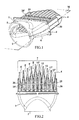
- a shaping accessory according to the invention is intended to be traversed by the air flow of a hairdressing apparatus S such as a hair dryer or a blower brush for applying air to a lock of hair to be shaped.
- the shaping accessory comprises a hollow body 1 provided with a proximal end 2 for connection to the outlet 3 of the hair-styling or hair-drying apparatus S as shown in FIG. figure 4 .
- the hollow body 1 has, opposite the proximal end 2, a distal end 4 of the air outlet and hair shaping.
- the hollow body 1 is formed by the assembly of two half-bodies 5 and 6 along a median plane M substantially parallel to a direction D of blowing the air at the outlet of the distal end 4.
- the distal end 4 is associated with at least one and, according to the example shown, two combs 7 for guiding the hair, parallel to each other and arranged on either side of the median plane M.
- the combs 7 are each integral part of the half body 5, 6 which carries it.
- Each guide comb 7 is formed of teeth 8 substantially parallel to each other and to the median plane M.
- the guide combs 7 are, according to the illustrated example, substantially symmetrical to one another with respect to the median plane M so that each guide tooth 8 of a comb 7 is disposed facing a guide tooth 8 of the other comb 7 being aligned with the latter in a direction substantially perpendicular to the median plane M.
- Each half-body 5.6 and its associated guide comb 7 are made by molding a suitable material such as a plastic or metal such as aluminum.
- a suitable material such as a plastic or metal such as aluminum.
- the half-bodies 5, 6 are made of an antistatic material such as, for example but not exclusively, a plastic material known under the name Permastat® whose antistatic properties result from a permanent surface treatment, stabilized in temperature.
- Permastat® whose antistatic properties result from a permanent surface treatment, stabilized in temperature.
- the distal end 4 is associated with hair clamping means which comprise, according to the invention, a clamping comb 10 placed between the guide combs 7 being parallel to them.
- the clamping comb 10 comprises a series of elastically deformable clamping teeth 11 which, according to the example illustrated, have a "V" shape whose tip is oriented in the blowing direction D.
- each clamping tooth 11 is formed of two elastic branches 12 which are connected at a core forming the head 13 and, here, the tip of the corresponding tooth.
- the head 13 is thus oriented towards the distal end 4 while the foot 14 of each clamping tooth 11, formed by the ends of the elastic branches 12 opposite the head, is oriented towards the proximal end 2.
- the clamping comb 10 is made in a folded metal strip, a little in the manner of an accordion, so that the clamping teeth 11 are interconnected one after the other by the ends of their resilient branches opposite their heads 13.
- the fold connecting the elastic branches 12 of two adjacent clamping teeth 11 is made so that said branches 12 are in contact with one another on at least part of their length as shown more particularly in the figure 3 .
- each head 13 of a clamping tooth 11 is aligned with two guide teeth 8, one of each guide comb 7, so that each space E of the hair clamping, defined by the branches view of two adjacent clamping teeth 11, opens between two adjacent guide teeth of each guide comb 7.
- the clamping comb 10 is, moreover, fixed to the hollow body 1 at two opposite lateral teeth 15 and 16 and more particularly at the ends of their outer branches.
- the at least 10 central clamping teeth and, in this case, all the clamping teeth 11 have a freedom of movement parallel to the median plane M and for the central teeth substantially parallel to the blowing direction D.
- the hollow body 1 comprises at least one stop, and according to the illustrated example a series of stops 17 against which the feet 14 of the clamping teeth 11 come into abutment when the clamping teeth 11 recede.
- the metal constituting the clamping comb may be of any suitable nature such as, for example, a copper or aluminum alloy or, preferably, a stainless steel. It may thus be chosen a stainless steel strip having a width of between 5 and 20 mm and a thickness of between 0.05 and 2 mm. To avoid excessive friction with the hair, the outer surface of the strip, intended to come into contact with the latter, may be subject to a surface treatment such as a fine polishing or a deposit of a coating type PTFE or enamel. The surface of the clamping teeth intended to be in contact with the hair may be flat or on the contrary present slight reliefs or pins.
- the forming accessory A thus formed can be permanently adapted to the body of the apparatus S or conversely removably by simple interlocking or by means of a bayonet fastening system for example.
- the shaping accessory of the invention can also be an integral part of the hairdressing apparatus S.
- the assembly consisting of the apparatus S and the shaping accessory is implemented in the following manner. Firstly, the apparatus is turned on so as to generate a flow of air passing through the hollow body 1 of the accessory A. If the air blown by the apparatus S is hot, the clamping comb 10 which is in the middle of the air flow will increase its temperature to reach a temperature close to that of the air directly at the exit of the apparatus S.
- the temperature of the clamping comb measured at the level of its central teeth will be able to for example, be between 50 ° C and 230 ° C, more preferably between 70 ° C and 90 ° C, or even between 75 ° C and 85 ° C.
- the guide teeth 8 are made, according to the example illustrated, so as to extend beyond the clamping teeth 11 in the direction or the blowing axis D for avoid direct contact of the clamping comb 10 with the scalp or the skin.
- the accessory A has additional means for protecting the clamping comb 10 formed here by lateral cheeks 20 preventing direct contact with the lateral clamping teeth 14 and 15.
- each tooth 8 of a guide comb 7 is connected at its head and beyond the clamping comb 10 to a tooth facing the other guide comb 7.
- each pair of guide teeth forms a kind of arch above the corresponding clamping tooth 10.
- the spacing between the adjacent teeth of the same guide comb can then be chosen to be less than one centimeter to prevent the passage of a finger between the guide teeth.
- the arch formed by the guide teeth 8 also defines a stop limiting the forward movement of the clamping teeth 11.
- Hair shaping by means of the invention will be performed after washing the hair and pre-drying the tips of the hair but not the part of the hair closest to the scalp. This formatting will also be performed on one side of the head and then on the other starting from the top of the skull.
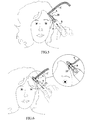
- the shaping accessory A is engaged, in the direction of the arrow F1, on a lock C of hair to be shaped which has been previously stretched as shown in FIG. figure 5 .
- This commitment is made by placing the accessory A close to the scalp or even against it.
- Engagement is advantageously performed at the base of the wick C.
- the hair of the wick C is distributed between the guide teeth and engage naturally in the clamping spaces E defined by the teeth 11 adjacent.
- the hair is sandwiched between the elastic branches 12.
- this engagement carried out in the direction of the arrow F1, has a tendency to push back the clamping teeth 11 relative to the hollow body 1 which contributes to increasing the tightening due to deformation induced on the clamping comb 10.
- the user maintains this position, illustrated figure 6 for a period of a few seconds, for example a duration greater than 2 seconds and which will be chosen according to the nature and the state of the scalp and the temperature of the clamping comb, which can be a duration greater than five seconds and, of preferably, of the order of ten seconds. As an indication, the duration is on average 5 seconds.
- the tension induced by the clamping comb 10 associated with the heating provided by the air flow, ensures a durable shaping of the hair so as to achieve an "inflated" hairstyle. The permanence of this shaping is further accentuated by the temperature of the clamping comb 10.
- the hair is then stretched and laid back, as shown.
- the shaping accessory is released from the lock of hair in the direction of arrow F2.
- the shaped wick is then folded up and the same operations are performed on a wick located below. This is done on each side of the head.
- one of the guide combs 7 may furthermore comprise a transverse counter-bar against which the hair comes into abutment during movement. A.
- the presence of the counterform bar 25 then induces an "S" type deformation between the part of the hair situated between the scalp and the bar and the part of the hair situated in the area. clamping space. This deformation contributes to the efficiency of the shaping.
- the bar will preferably be placed opposite the scalp relative to the clamping comb.
- the bar against the shape of the hair may extend distally relative to the bottom F of the hair clamping teeth defined by the hair clamping means.
- the head of the guide teeth 8 has a side view, perpendicularly in the median plane, an arched or ogival shape so that the guide teeth do not have a sharp angle at their end.
- the vertices of the heads of the guide teeth, seen along the median plane form an arched line, as shown more particularly by the figure 2 .
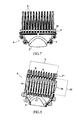
- the Figures 7 and 8 illustrate another embodiment of an accessory for shaping hair that differs from that described in connection with the Figures 1 to 6 in that the tips of the guide teeth 8 are aligned along a straight line and not along an arcuate line. According to this example, it is also not implemented two side cheeks so that the lateral teeth 15 and 16 of the clamping comb 10 are directly accessible. Moreover, according to this exemplary embodiment, the counterform bar 25 is not part of integral of the half-body that carries it as shown Figures 1 and 2 but on the contrary is reported on the teeth 8 of a guide comb 7.
- each tooth 8 of a guide comb 7 is not necessarily linked to a tooth of another guide comb.
- Figures 9 to 11 illustrate another embodiment of an accessory for shaping hair in which the heads of the guide teeth are independent of each other.
- the guide teeth 8 have a generally cylindrical shape, whereas according to the previously described examples, the guide teeth 8 have a flattened shape substantially perpendicular to the median plane M.
- the clamping teeth are generally U-shaped.
- the heads 13 of the clamping teeth 11 form an arcuate line which gives the assembly of the clamping comb a slightly arched shape in the median plane M which contributes to increasing its ability to deform parallel to the median plane M.
- the heating of the clamping comb 10 results from its contact with the air heated by the apparatus S.
- dedicated heating means such as that, for example, an electrical resistance that would be integrated.
- the clamping comb is made of metal however it could be made of any other material having good elasticity characteristics, so it could be made of plastic material such as polypropylene.
- the clamping comb 10 is preferably made of a thermally conductive material this characteristic is not strictly necessary for the production of a clamping comb according to the invention.
- the whole of the clamping comb is not necessarily made by folding but could result from the assembly of clamping teeth 11 produced individually.
Landscapes
- Cleaning And Drying Hair (AREA)
- Brushes (AREA)
Applications Claiming Priority (1)
| Application Number | Priority Date | Filing Date | Title |
|---|---|---|---|
| FR1060276A FR2968511B1 (fr) | 2010-12-08 | 2010-12-08 | Accessoire de mise en forme de cheveux |
Publications (3)
| Publication Number | Publication Date |
|---|---|
| EP2462831A2 true EP2462831A2 (de) | 2012-06-13 |
| EP2462831A3 EP2462831A3 (de) | 2012-06-27 |
| EP2462831B1 EP2462831B1 (de) | 2017-07-19 |
Family
ID=44246279
Family Applications (1)
| Application Number | Title | Priority Date | Filing Date |
|---|---|---|---|
| EP11306616.1A Active EP2462831B1 (de) | 2010-12-08 | 2011-12-06 | Haarformzubehör |
Country Status (4)
| Country | Link |
|---|---|
| EP (1) | EP2462831B1 (de) |
| CN (1) | CN102525080B (de) |
| ES (1) | ES2637946T3 (de) |
| FR (1) | FR2968511B1 (de) |
Cited By (7)
| Publication number | Priority date | Publication date | Assignee | Title |
|---|---|---|---|---|
| US10660418B2 (en) | 2017-07-14 | 2020-05-26 | Spectrum Brands, Inc. | Air-moving appliance including an attachment |
| US10835007B2 (en) | 2017-07-14 | 2020-11-17 | Spectrum Brands, Inc. | Hair dryer |
| US20210289909A1 (en) * | 2018-08-01 | 2021-09-23 | Dyson Technology Limited | Attachment for a handheld appliance |
| CN113438912A (zh) * | 2018-10-17 | 2021-09-24 | J·道金斯 | 头发定型系统 |
| US20210298445A1 (en) * | 2018-08-01 | 2021-09-30 | Dyson Technology Limited | Attachment for a handheld appliance |
| US11230021B2 (en) | 2018-02-20 | 2022-01-25 | Koninklijke Philips N.V. | Comb for a hair clipper |
| WO2025049171A1 (en) * | 2023-08-25 | 2025-03-06 | Sharkninja Operating Llc | Heated hair comb attachment |
Families Citing this family (9)
| Publication number | Priority date | Publication date | Assignee | Title |
|---|---|---|---|---|
| US11311098B2 (en) * | 2016-10-31 | 2022-04-26 | L'Oreál | Hair coloring appliance |
| EP3530139B1 (de) * | 2018-02-23 | 2020-10-07 | Kan Holding AS | Frisiervorrichtung |
| US11857052B2 (en) | 2020-04-01 | 2024-01-02 | Omachron Intellectual Property Inc. | Water separator for a hair dryer |
| GB2602283B (en) * | 2020-12-22 | 2023-11-15 | Dyson Technology Ltd | A haircare appliance |
| USD1021238S1 (en) | 2022-06-02 | 2024-04-02 | Sharkninja Operating Llc | Hair care appliance |
| USD1016390S1 (en) | 2022-11-07 | 2024-02-27 | Sharkninja Operating Llc | Comb |
| KR20250154586A (ko) | 2023-01-19 | 2025-10-28 | 샤크닌자 오퍼레이팅 엘엘씨 | 전력 공급 부착물을 갖는 헤어 케어 기기 |
| US20240245190A1 (en) | 2023-01-19 | 2024-07-25 | Sharkninja Operating Llc | Identification of hair care appliance attachments |
| KR20250129311A (ko) * | 2024-02-22 | 2025-08-29 | 엘지전자 주식회사 | 헤어 스타일링 노즐 및 헤어 드라이어 |
Citations (1)
| Publication number | Priority date | Publication date | Assignee | Title |
|---|---|---|---|---|
| EP1898740A2 (de) | 2005-07-05 | 2008-03-19 | Seb Sa | Haarbehandlungsvorrichtung und damit versehenes haarbehandlungsgerät |
Family Cites Families (8)
| Publication number | Priority date | Publication date | Assignee | Title |
|---|---|---|---|---|
| FR2785159B1 (fr) * | 1998-10-30 | 2000-12-22 | Seb Sa | Accessoire pour le lissage des cheveux |
| KR100414343B1 (ko) * | 2001-08-27 | 2004-01-07 | 박정훈 | 드라이어를 구비한 초음파 진동형 머리빗 |
| ATE372693T1 (de) * | 2005-06-13 | 2007-09-15 | Faco Sa | Vorrichtung zum ausrichten von haaren |
| JP5023145B2 (ja) * | 2006-05-18 | 2012-09-12 | バビリス ファコ ソシエテ アノニム | 改善された毛髪ストレート化装置 |
| MX2009001125A (es) * | 2006-08-01 | 2009-04-14 | Tenacta Group Spa | Dispositivo adaptado para liberar una sustancia capilar. |
| FR2916945B1 (fr) * | 2007-06-05 | 2009-07-17 | Seb Sa | Appareil de traitement des cheveux |
| US8302613B2 (en) * | 2007-07-20 | 2012-11-06 | Wahl Clipper Corporation | Conditioner applicator for hair styling device |
| FR2933852B1 (fr) * | 2008-07-21 | 2011-03-25 | Seb Sa | Dispositif de lissage des cheveux integrant des moyens de chauffage |
-
2010
- 2010-12-08 FR FR1060276A patent/FR2968511B1/fr active Active
-
2011
- 2011-12-06 EP EP11306616.1A patent/EP2462831B1/de active Active
- 2011-12-06 ES ES11306616.1T patent/ES2637946T3/es active Active
- 2011-12-07 CN CN201110404369.5A patent/CN102525080B/zh active Active
Patent Citations (1)
| Publication number | Priority date | Publication date | Assignee | Title |
|---|---|---|---|---|
| EP1898740A2 (de) | 2005-07-05 | 2008-03-19 | Seb Sa | Haarbehandlungsvorrichtung und damit versehenes haarbehandlungsgerät |
Cited By (10)
| Publication number | Priority date | Publication date | Assignee | Title |
|---|---|---|---|---|
| US10660418B2 (en) | 2017-07-14 | 2020-05-26 | Spectrum Brands, Inc. | Air-moving appliance including an attachment |
| US10835007B2 (en) | 2017-07-14 | 2020-11-17 | Spectrum Brands, Inc. | Hair dryer |
| US11311090B2 (en) | 2017-07-14 | 2022-04-26 | Spectrum Brands, Inc. | Hair dryer |
| US11330884B2 (en) | 2017-07-14 | 2022-05-17 | Spectrum Brands, Inc. | Air-moving appliance including an attachment |
| US11877638B2 (en) | 2017-07-14 | 2024-01-23 | Spectrum Brands, Inc. | Air-moving appliance including an attachment |
| US11230021B2 (en) | 2018-02-20 | 2022-01-25 | Koninklijke Philips N.V. | Comb for a hair clipper |
| US20210289909A1 (en) * | 2018-08-01 | 2021-09-23 | Dyson Technology Limited | Attachment for a handheld appliance |
| US20210298445A1 (en) * | 2018-08-01 | 2021-09-30 | Dyson Technology Limited | Attachment for a handheld appliance |
| CN113438912A (zh) * | 2018-10-17 | 2021-09-24 | J·道金斯 | 头发定型系统 |
| WO2025049171A1 (en) * | 2023-08-25 | 2025-03-06 | Sharkninja Operating Llc | Heated hair comb attachment |
Also Published As
| Publication number | Publication date |
|---|---|
| FR2968511B1 (fr) | 2013-10-18 |
| CN102525080A (zh) | 2012-07-04 |
| CN102525080B (zh) | 2016-12-21 |
| EP2462831B1 (de) | 2017-07-19 |
| FR2968511A1 (fr) | 2012-06-15 |
| EP2462831A3 (de) | 2012-06-27 |
| ES2637946T3 (es) | 2017-10-18 |
Similar Documents
| Publication | Publication Date | Title |
|---|---|---|
| EP2462831B1 (de) | Haarformzubehör | |
| EP2378916B1 (de) | Frisiervorrichtung mit klammern | |
| EP2757922B1 (de) | Frisierzubehör für einen haartrockner | |
| EP0659363B1 (de) | Vorrichtung zur Behandlung von Haaren mit Dampf | |
| FR3049830B1 (fr) | Accessoire de coiffure ouvert et appareil de coiffure equipe d'un tel accessoire | |
| EP1124466B1 (de) | Zubehör zum glätten von haaren | |
| WO2015173507A1 (fr) | Appareil de coiffure a vapeur via surface de traitement et avec peigne | |
| EP2836094B1 (de) | Backenartige frisiervorrichtung mit einziehbarem kamm | |
| FR2782904A1 (fr) | Seche-cheveux a air chaud et a air froid simultanes | |
| EP3727076B1 (de) | Haarbehandlungsgerät mit dampfeinschluss | |
| EP3220769B1 (de) | Frisiergerät mit wärmeisolationsmittel | |
| FR2978332A1 (fr) | Brosse a cheveux electrique avec accessoire evolutif | |
| EP2312967A2 (de) | Haarglättungsvorrichtung mit einem eingebauten heizmittel | |
| EP1139813B1 (de) | Haarspange | |
| FR3134694A1 (fr) | Dispositif de traitement de la chevelure | |
| EP3478116B1 (de) | Haarglättvorrichtung mit optimierter bürste | |
| EP2584930B1 (de) | Vorrichtung für haarstyling mit backen | |
| EP0107748A1 (de) | Kombiniertes Saug- und Trockenverfahren sowie Vorrichtung zur Haarformung | |
| FR3134692A1 (fr) | Procédé de traitement des cheveux | |
| CH661419A5 (fr) | Brosse a brushing. | |
| FR2998143A1 (fr) | Gant de protection | |
| BE508449A (de) |
Legal Events
| Date | Code | Title | Description |
|---|---|---|---|
| PUAL | Search report despatched |
Free format text: ORIGINAL CODE: 0009013 |
|
| PUAI | Public reference made under article 153(3) epc to a published international application that has entered the european phase |
Free format text: ORIGINAL CODE: 0009012 |
|
| AK | Designated contracting states |
Kind code of ref document: A2 Designated state(s): AL AT BE BG CH CY CZ DE DK EE ES FI FR GB GR HR HU IE IS IT LI LT LU LV MC MK MT NL NO PL PT RO RS SE SI SK SM TR |
|
| AX | Request for extension of the european patent |
Extension state: BA ME |
|
| AK | Designated contracting states |
Kind code of ref document: A3 Designated state(s): AL AT BE BG CH CY CZ DE DK EE ES FI FR GB GR HR HU IE IS IT LI LT LU LV MC MK MT NL NO PL PT RO RS SE SI SK SM TR |
|
| AX | Request for extension of the european patent |
Extension state: BA ME |
|
| RIC1 | Information provided on ipc code assigned before grant |
Ipc: A45D 20/52 20060101ALI20120521BHEP Ipc: A45D 20/12 20060101AFI20120521BHEP |
|
| 17P | Request for examination filed |
Effective date: 20121219 |
|
| RAP1 | Party data changed (applicant data changed or rights of an application transferred) |
Owner name: SEB S.A. |
|
| GRAP | Despatch of communication of intention to grant a patent |
Free format text: ORIGINAL CODE: EPIDOSNIGR1 |
|
| INTG | Intention to grant announced |
Effective date: 20170206 |
|
| GRAS | Grant fee paid |
Free format text: ORIGINAL CODE: EPIDOSNIGR3 |
|
| GRAA | (expected) grant |
Free format text: ORIGINAL CODE: 0009210 |
|
| AK | Designated contracting states |
Kind code of ref document: B1 Designated state(s): AL AT BE BG CH CY CZ DE DK EE ES FI FR GB GR HR HU IE IS IT LI LT LU LV MC MK MT NL NO PL PT RO RS SE SI SK SM TR |
|
| REG | Reference to a national code |
Ref country code: GB Ref legal event code: FG4D Free format text: NOT ENGLISH |
|
| REG | Reference to a national code |
Ref country code: CH Ref legal event code: EP |
|
| REG | Reference to a national code |
Ref country code: IE Ref legal event code: FG4D Free format text: LANGUAGE OF EP DOCUMENT: FRENCH |
|
| REG | Reference to a national code |
Ref country code: AT Ref legal event code: REF Ref document number: 909514 Country of ref document: AT Kind code of ref document: T Effective date: 20170815 |
|
| REG | Reference to a national code |
Ref country code: DE Ref legal event code: R096 Ref document number: 602011039662 Country of ref document: DE |
|
| REG | Reference to a national code |
Ref country code: ES Ref legal event code: FG2A Ref document number: 2637946 Country of ref document: ES Kind code of ref document: T3 Effective date: 20171018 |
|
| REG | Reference to a national code |
Ref country code: NL Ref legal event code: MP Effective date: 20170719 |
|
| REG | Reference to a national code |
Ref country code: LT Ref legal event code: MG4D |
|
| REG | Reference to a national code |
Ref country code: AT Ref legal event code: MK05 Ref document number: 909514 Country of ref document: AT Kind code of ref document: T Effective date: 20170719 |
|
| REG | Reference to a national code |
Ref country code: FR Ref legal event code: PLFP Year of fee payment: 7 |
|
| PG25 | Lapsed in a contracting state [announced via postgrant information from national office to epo] |
Ref country code: HR Free format text: LAPSE BECAUSE OF FAILURE TO SUBMIT A TRANSLATION OF THE DESCRIPTION OR TO PAY THE FEE WITHIN THE PRESCRIBED TIME-LIMIT Effective date: 20170719 Ref country code: LT Free format text: LAPSE BECAUSE OF FAILURE TO SUBMIT A TRANSLATION OF THE DESCRIPTION OR TO PAY THE FEE WITHIN THE PRESCRIBED TIME-LIMIT Effective date: 20170719 Ref country code: SE Free format text: LAPSE BECAUSE OF FAILURE TO SUBMIT A TRANSLATION OF THE DESCRIPTION OR TO PAY THE FEE WITHIN THE PRESCRIBED TIME-LIMIT Effective date: 20170719 Ref country code: FI Free format text: LAPSE BECAUSE OF FAILURE TO SUBMIT A TRANSLATION OF THE DESCRIPTION OR TO PAY THE FEE WITHIN THE PRESCRIBED TIME-LIMIT Effective date: 20170719 Ref country code: NL Free format text: LAPSE BECAUSE OF FAILURE TO SUBMIT A TRANSLATION OF THE DESCRIPTION OR TO PAY THE FEE WITHIN THE PRESCRIBED TIME-LIMIT Effective date: 20170719 Ref country code: AT Free format text: LAPSE BECAUSE OF FAILURE TO SUBMIT A TRANSLATION OF THE DESCRIPTION OR TO PAY THE FEE WITHIN THE PRESCRIBED TIME-LIMIT Effective date: 20170719 Ref country code: NO Free format text: LAPSE BECAUSE OF FAILURE TO SUBMIT A TRANSLATION OF THE DESCRIPTION OR TO PAY THE FEE WITHIN THE PRESCRIBED TIME-LIMIT Effective date: 20171019 |
|
| PG25 | Lapsed in a contracting state [announced via postgrant information from national office to epo] |
Ref country code: BG Free format text: LAPSE BECAUSE OF FAILURE TO SUBMIT A TRANSLATION OF THE DESCRIPTION OR TO PAY THE FEE WITHIN THE PRESCRIBED TIME-LIMIT Effective date: 20171019 Ref country code: LV Free format text: LAPSE BECAUSE OF FAILURE TO SUBMIT A TRANSLATION OF THE DESCRIPTION OR TO PAY THE FEE WITHIN THE PRESCRIBED TIME-LIMIT Effective date: 20170719 Ref country code: GR Free format text: LAPSE BECAUSE OF FAILURE TO SUBMIT A TRANSLATION OF THE DESCRIPTION OR TO PAY THE FEE WITHIN THE PRESCRIBED TIME-LIMIT Effective date: 20171020 Ref country code: IS Free format text: LAPSE BECAUSE OF FAILURE TO SUBMIT A TRANSLATION OF THE DESCRIPTION OR TO PAY THE FEE WITHIN THE PRESCRIBED TIME-LIMIT Effective date: 20171119 Ref country code: PL Free format text: LAPSE BECAUSE OF FAILURE TO SUBMIT A TRANSLATION OF THE DESCRIPTION OR TO PAY THE FEE WITHIN THE PRESCRIBED TIME-LIMIT Effective date: 20170719 Ref country code: RS Free format text: LAPSE BECAUSE OF FAILURE TO SUBMIT A TRANSLATION OF THE DESCRIPTION OR TO PAY THE FEE WITHIN THE PRESCRIBED TIME-LIMIT Effective date: 20170719 |
|
| REG | Reference to a national code |
Ref country code: DE Ref legal event code: R097 Ref document number: 602011039662 Country of ref document: DE |
|
| PG25 | Lapsed in a contracting state [announced via postgrant information from national office to epo] |
Ref country code: DK Free format text: LAPSE BECAUSE OF FAILURE TO SUBMIT A TRANSLATION OF THE DESCRIPTION OR TO PAY THE FEE WITHIN THE PRESCRIBED TIME-LIMIT Effective date: 20170719 Ref country code: RO Free format text: LAPSE BECAUSE OF FAILURE TO SUBMIT A TRANSLATION OF THE DESCRIPTION OR TO PAY THE FEE WITHIN THE PRESCRIBED TIME-LIMIT Effective date: 20170719 Ref country code: CZ Free format text: LAPSE BECAUSE OF FAILURE TO SUBMIT A TRANSLATION OF THE DESCRIPTION OR TO PAY THE FEE WITHIN THE PRESCRIBED TIME-LIMIT Effective date: 20170719 |
|
| PLBE | No opposition filed within time limit |
Free format text: ORIGINAL CODE: 0009261 |
|
| STAA | Information on the status of an ep patent application or granted ep patent |
Free format text: STATUS: NO OPPOSITION FILED WITHIN TIME LIMIT |
|
| PG25 | Lapsed in a contracting state [announced via postgrant information from national office to epo] |
Ref country code: SM Free format text: LAPSE BECAUSE OF FAILURE TO SUBMIT A TRANSLATION OF THE DESCRIPTION OR TO PAY THE FEE WITHIN THE PRESCRIBED TIME-LIMIT Effective date: 20170719 Ref country code: EE Free format text: LAPSE BECAUSE OF FAILURE TO SUBMIT A TRANSLATION OF THE DESCRIPTION OR TO PAY THE FEE WITHIN THE PRESCRIBED TIME-LIMIT Effective date: 20170719 Ref country code: SK Free format text: LAPSE BECAUSE OF FAILURE TO SUBMIT A TRANSLATION OF THE DESCRIPTION OR TO PAY THE FEE WITHIN THE PRESCRIBED TIME-LIMIT Effective date: 20170719 |
|
| 26N | No opposition filed |
Effective date: 20180420 |
|
| REG | Reference to a national code |
Ref country code: CH Ref legal event code: PL |
|
| GBPC | Gb: european patent ceased through non-payment of renewal fee |
Effective date: 20171206 |
|
| PG25 | Lapsed in a contracting state [announced via postgrant information from national office to epo] |
Ref country code: SI Free format text: LAPSE BECAUSE OF FAILURE TO SUBMIT A TRANSLATION OF THE DESCRIPTION OR TO PAY THE FEE WITHIN THE PRESCRIBED TIME-LIMIT Effective date: 20170719 |
|
| REG | Reference to a national code |
Ref country code: IE Ref legal event code: MM4A |
|
| PG25 | Lapsed in a contracting state [announced via postgrant information from national office to epo] |
Ref country code: MT Free format text: LAPSE BECAUSE OF FAILURE TO SUBMIT A TRANSLATION OF THE DESCRIPTION OR TO PAY THE FEE WITHIN THE PRESCRIBED TIME-LIMIT Effective date: 20170719 Ref country code: LU Free format text: LAPSE BECAUSE OF NON-PAYMENT OF DUE FEES Effective date: 20171206 |
|
| REG | Reference to a national code |
Ref country code: BE Ref legal event code: MM Effective date: 20171231 |
|
| PG25 | Lapsed in a contracting state [announced via postgrant information from national office to epo] |
Ref country code: IE Free format text: LAPSE BECAUSE OF NON-PAYMENT OF DUE FEES Effective date: 20171206 |
|
| PG25 | Lapsed in a contracting state [announced via postgrant information from national office to epo] |
Ref country code: GB Free format text: LAPSE BECAUSE OF NON-PAYMENT OF DUE FEES Effective date: 20171206 Ref country code: BE Free format text: LAPSE BECAUSE OF NON-PAYMENT OF DUE FEES Effective date: 20171231 Ref country code: LI Free format text: LAPSE BECAUSE OF NON-PAYMENT OF DUE FEES Effective date: 20171231 Ref country code: CH Free format text: LAPSE BECAUSE OF NON-PAYMENT OF DUE FEES Effective date: 20171231 |
|
| PG25 | Lapsed in a contracting state [announced via postgrant information from national office to epo] |
Ref country code: MC Free format text: LAPSE BECAUSE OF FAILURE TO SUBMIT A TRANSLATION OF THE DESCRIPTION OR TO PAY THE FEE WITHIN THE PRESCRIBED TIME-LIMIT Effective date: 20170719 Ref country code: HU Free format text: LAPSE BECAUSE OF FAILURE TO SUBMIT A TRANSLATION OF THE DESCRIPTION OR TO PAY THE FEE WITHIN THE PRESCRIBED TIME-LIMIT; INVALID AB INITIO Effective date: 20111206 |
|
| PG25 | Lapsed in a contracting state [announced via postgrant information from national office to epo] |
Ref country code: CY Free format text: LAPSE BECAUSE OF NON-PAYMENT OF DUE FEES Effective date: 20170719 |
|
| PG25 | Lapsed in a contracting state [announced via postgrant information from national office to epo] |
Ref country code: MK Free format text: LAPSE BECAUSE OF FAILURE TO SUBMIT A TRANSLATION OF THE DESCRIPTION OR TO PAY THE FEE WITHIN THE PRESCRIBED TIME-LIMIT Effective date: 20170719 |
|
| PG25 | Lapsed in a contracting state [announced via postgrant information from national office to epo] |
Ref country code: TR Free format text: LAPSE BECAUSE OF FAILURE TO SUBMIT A TRANSLATION OF THE DESCRIPTION OR TO PAY THE FEE WITHIN THE PRESCRIBED TIME-LIMIT Effective date: 20170719 |
|
| PG25 | Lapsed in a contracting state [announced via postgrant information from national office to epo] |
Ref country code: PT Free format text: LAPSE BECAUSE OF FAILURE TO SUBMIT A TRANSLATION OF THE DESCRIPTION OR TO PAY THE FEE WITHIN THE PRESCRIBED TIME-LIMIT Effective date: 20170719 |
|
| PG25 | Lapsed in a contracting state [announced via postgrant information from national office to epo] |
Ref country code: AL Free format text: LAPSE BECAUSE OF FAILURE TO SUBMIT A TRANSLATION OF THE DESCRIPTION OR TO PAY THE FEE WITHIN THE PRESCRIBED TIME-LIMIT Effective date: 20170719 |
|
| PGFP | Annual fee paid to national office [announced via postgrant information from national office to epo] |
Ref country code: IT Payment date: 20201214 Year of fee payment: 10 |
|
| PG25 | Lapsed in a contracting state [announced via postgrant information from national office to epo] |
Ref country code: IT Free format text: LAPSE BECAUSE OF NON-PAYMENT OF DUE FEES Effective date: 20211206 |
|
| PGFP | Annual fee paid to national office [announced via postgrant information from national office to epo] |
Ref country code: DE Payment date: 20241211 Year of fee payment: 14 |
|
| PGFP | Annual fee paid to national office [announced via postgrant information from national office to epo] |
Ref country code: FR Payment date: 20251230 Year of fee payment: 15 |
|
| PGFP | Annual fee paid to national office [announced via postgrant information from national office to epo] |
Ref country code: ES Payment date: 20260112 Year of fee payment: 15 |