EP2462955A2 - Appareil et procédé de désodorisation et de stérilisation - Google Patents
Appareil et procédé de désodorisation et de stérilisation Download PDFInfo
- Publication number
- EP2462955A2 EP2462955A2 EP11191821A EP11191821A EP2462955A2 EP 2462955 A2 EP2462955 A2 EP 2462955A2 EP 11191821 A EP11191821 A EP 11191821A EP 11191821 A EP11191821 A EP 11191821A EP 2462955 A2 EP2462955 A2 EP 2462955A2
- Authority
- EP
- European Patent Office
- Prior art keywords
- fluid passage
- absorption member
- deodorization
- passage holes
- absorption
- Prior art date
- Legal status (The legal status is an assumption and is not a legal conclusion. Google has not performed a legal analysis and makes no representation as to the accuracy of the status listed.)
- Granted
Links
Images








Classifications
-
- A—HUMAN NECESSITIES
- A61—MEDICAL OR VETERINARY SCIENCE; HYGIENE
- A61L—METHODS OR APPARATUS FOR STERILISING MATERIALS OR OBJECTS IN GENERAL; DISINFECTION, STERILISATION OR DEODORISATION OF AIR; CHEMICAL ASPECTS OF BANDAGES, DRESSINGS, ABSORBENT PADS OR SURGICAL ARTICLES; MATERIALS FOR BANDAGES, DRESSINGS, ABSORBENT PADS OR SURGICAL ARTICLES
- A61L9/00—Disinfection, sterilisation or deodorisation of air
- A61L9/16—Disinfection, sterilisation or deodorisation of air using physical phenomena
- A61L9/22—Ionisation
-
- A—HUMAN NECESSITIES
- A61—MEDICAL OR VETERINARY SCIENCE; HYGIENE
- A61L—METHODS OR APPARATUS FOR STERILISING MATERIALS OR OBJECTS IN GENERAL; DISINFECTION, STERILISATION OR DEODORISATION OF AIR; CHEMICAL ASPECTS OF BANDAGES, DRESSINGS, ABSORBENT PADS OR SURGICAL ARTICLES; MATERIALS FOR BANDAGES, DRESSINGS, ABSORBENT PADS OR SURGICAL ARTICLES
- A61L9/00—Disinfection, sterilisation or deodorisation of air
- A61L9/01—Deodorant compositions
- A61L9/014—Deodorant compositions containing sorbent material, e.g. activated carbon
-
- B—PERFORMING OPERATIONS; TRANSPORTING
- B03—SEPARATION OF SOLID MATERIALS USING LIQUIDS OR USING PNEUMATIC TABLES OR JIGS; MAGNETIC OR ELECTROSTATIC SEPARATION OF SOLID MATERIALS FROM SOLID MATERIALS OR FLUIDS; SEPARATION BY HIGH-VOLTAGE ELECTRIC FIELDS
- B03C—MAGNETIC OR ELECTROSTATIC SEPARATION OF SOLID MATERIALS FROM SOLID MATERIALS OR FLUIDS; SEPARATION BY HIGH-VOLTAGE ELECTRIC FIELDS
- B03C3/00—Separating dispersed particles from gases or vapour, e.g. air, by electrostatic effect
- B03C3/34—Constructional details or accessories or operation thereof
- B03C3/38—Particle charging or ionising stations, e.g. using electric discharge, radioactive radiation or flames
-
- F—MECHANICAL ENGINEERING; LIGHTING; HEATING; WEAPONS; BLASTING
- F24—HEATING; RANGES; VENTILATING
- F24F—AIR-CONDITIONING; AIR-HUMIDIFICATION; VENTILATION; USE OF AIR CURRENTS FOR SCREENING
- F24F3/00—Air-conditioning systems in which conditioned primary air is supplied from one or more central stations to distributing units in the rooms or spaces where it may receive secondary treatment; Apparatus specially designed for such systems
- F24F3/12—Air-conditioning systems in which conditioned primary air is supplied from one or more central stations to distributing units in the rooms or spaces where it may receive secondary treatment; Apparatus specially designed for such systems characterised by the treatment of the air otherwise than by heating and cooling
- F24F3/16—Air-conditioning systems in which conditioned primary air is supplied from one or more central stations to distributing units in the rooms or spaces where it may receive secondary treatment; Apparatus specially designed for such systems characterised by the treatment of the air otherwise than by heating and cooling by purification, e.g. by filtering; by sterilisation; by ozonisation
-
- F—MECHANICAL ENGINEERING; LIGHTING; HEATING; WEAPONS; BLASTING
- F24—HEATING; RANGES; VENTILATING
- F24F—AIR-CONDITIONING; AIR-HUMIDIFICATION; VENTILATION; USE OF AIR CURRENTS FOR SCREENING
- F24F8/00—Treatment, e.g. purification, of air supplied to human living or working spaces otherwise than by heating, cooling, humidifying or drying
- F24F8/20—Treatment, e.g. purification, of air supplied to human living or working spaces otherwise than by heating, cooling, humidifying or drying by sterilisation
-
- F—MECHANICAL ENGINEERING; LIGHTING; HEATING; WEAPONS; BLASTING
- F24—HEATING; RANGES; VENTILATING
- F24F—AIR-CONDITIONING; AIR-HUMIDIFICATION; VENTILATION; USE OF AIR CURRENTS FOR SCREENING
- F24F8/00—Treatment, e.g. purification, of air supplied to human living or working spaces otherwise than by heating, cooling, humidifying or drying
- F24F8/20—Treatment, e.g. purification, of air supplied to human living or working spaces otherwise than by heating, cooling, humidifying or drying by sterilisation
- F24F8/22—Treatment, e.g. purification, of air supplied to human living or working spaces otherwise than by heating, cooling, humidifying or drying by sterilisation using UV light
-
- F—MECHANICAL ENGINEERING; LIGHTING; HEATING; WEAPONS; BLASTING
- F24—HEATING; RANGES; VENTILATING
- F24F—AIR-CONDITIONING; AIR-HUMIDIFICATION; VENTILATION; USE OF AIR CURRENTS FOR SCREENING
- F24F8/00—Treatment, e.g. purification, of air supplied to human living or working spaces otherwise than by heating, cooling, humidifying or drying
- F24F8/30—Treatment, e.g. purification, of air supplied to human living or working spaces otherwise than by heating, cooling, humidifying or drying by ionisation
-
- H—ELECTRICITY
- H01—ELECTRIC ELEMENTS
- H01T—SPARK GAPS; OVERVOLTAGE ARRESTERS USING SPARK GAPS; SPARKING PLUGS; CORONA DEVICES; GENERATING IONS TO BE INTRODUCED INTO NON-ENCLOSED GASES
- H01T23/00—Apparatus for generating ions to be introduced into non-enclosed gases, e.g. into the atmosphere
-
- H—ELECTRICITY
- H05—ELECTRIC TECHNIQUES NOT OTHERWISE PROVIDED FOR
- H05H—PLASMA TECHNIQUE; PRODUCTION OF ACCELERATED ELECTRICALLY-CHARGED PARTICLES OR OF NEUTRONS; PRODUCTION OR ACCELERATION OF NEUTRAL MOLECULAR OR ATOMIC BEAMS
- H05H1/00—Generating plasma; Handling plasma
- H05H1/24—Generating plasma
- H05H1/2406—Generating plasma using dielectric barrier discharges, i.e. with a dielectric interposed between the electrodes
-
- A—HUMAN NECESSITIES
- A61—MEDICAL OR VETERINARY SCIENCE; HYGIENE
- A61L—METHODS OR APPARATUS FOR STERILISING MATERIALS OR OBJECTS IN GENERAL; DISINFECTION, STERILISATION OR DEODORISATION OF AIR; CHEMICAL ASPECTS OF BANDAGES, DRESSINGS, ABSORBENT PADS OR SURGICAL ARTICLES; MATERIALS FOR BANDAGES, DRESSINGS, ABSORBENT PADS OR SURGICAL ARTICLES
- A61L2209/00—Aspects relating to disinfection, sterilisation or deodorisation of air
- A61L2209/10—Apparatus features
-
- A—HUMAN NECESSITIES
- A61—MEDICAL OR VETERINARY SCIENCE; HYGIENE
- A61L—METHODS OR APPARATUS FOR STERILISING MATERIALS OR OBJECTS IN GENERAL; DISINFECTION, STERILISATION OR DEODORISATION OF AIR; CHEMICAL ASPECTS OF BANDAGES, DRESSINGS, ABSORBENT PADS OR SURGICAL ARTICLES; MATERIALS FOR BANDAGES, DRESSINGS, ABSORBENT PADS OR SURGICAL ARTICLES
- A61L2209/00—Aspects relating to disinfection, sterilisation or deodorisation of air
- A61L2209/20—Method-related aspects
- A61L2209/22—Treatment by sorption, e.g. absorption, adsorption, chemisorption, scrubbing, wet cleaning
-
- F—MECHANICAL ENGINEERING; LIGHTING; HEATING; WEAPONS; BLASTING
- F24—HEATING; RANGES; VENTILATING
- F24F—AIR-CONDITIONING; AIR-HUMIDIFICATION; VENTILATION; USE OF AIR CURRENTS FOR SCREENING
- F24F8/00—Treatment, e.g. purification, of air supplied to human living or working spaces otherwise than by heating, cooling, humidifying or drying
- F24F8/50—Treatment, e.g. purification, of air supplied to human living or working spaces otherwise than by heating, cooling, humidifying or drying by odorisation
-
- H—ELECTRICITY
- H05—ELECTRIC TECHNIQUES NOT OTHERWISE PROVIDED FOR
- H05H—PLASMA TECHNIQUE; PRODUCTION OF ACCELERATED ELECTRICALLY-CHARGED PARTICLES OR OF NEUTRONS; PRODUCTION OR ACCELERATION OF NEUTRAL MOLECULAR OR ATOMIC BEAMS
- H05H2245/00—Applications of plasma devices
- H05H2245/30—Medical applications
- H05H2245/36—Sterilisation of objects, liquids, volumes or surfaces
Definitions
- the present invention relates to a deodorization and sterilization apparatus and method, and more particularly, a deodorization and sterilization apparatus and method, which increases an amount of generated active species and collects floating bacteria or odor materials in air at one place, such that the active species make contact with the collected floating bacteria or odor materials to achieve high-efficiency sterilization and deodorization.
- active species ions or radicals
- the passive plasma generation apparatus may be advantageous in that high sterilization and deodorization effects are expected through generation of active species of a high concentration due to generation of plasma in a small volume.
- the passive plasma generation apparatus may be disadvantageous in that the floating bacteria or odors need to be introduced into the apparatus, and thus, the size of the apparatus is increased, ozone as a byproduct due to plasma generation is generated, and separate installation of a filter to absorb or decompose ozone to prevent ozone from leaking to the outside of the apparatus is required.
- the active plasma generation apparatus may be advantageous in that the size of the apparatus is relatively decreased and sterilization of bacteria attached to the surfaces of clothes or household goods (hereinafter, referred to as attached bacteria) or decomposition of odors absorbed to the surfaces is expected, in addition to sterilization of floating bacteria or decomposition of odors in air.
- attached bacteria bacteria attached to the surfaces of clothes or household goods
- decomposition of odors absorbed to the surfaces is expected, in addition to sterilization of floating bacteria or decomposition of odors in air.
- the active plasma generation apparatus may be disadvantageous in that the concentration of active species is decreased due to diffusion of the active species into a considerably large closed space as compared with the volume of the apparatus, and thus, sterilization and deodorization are expected only upon active species having a long life. Consequently, deodorization effects are scarcely expected in a space having a high concentration of odors (concentration 10,000 times greater than the concentration of the active species).
- the passive plasma generation apparatus exhibits effects restricted to floating bacteria or odors contained in an air flow introduced into the apparatus, and the active plasma generation apparatus exhibits effects only upon floating bacteria, attached bacteria and odors having a low concentration. That is, the conventional plasma generation apparatuses may achieve either sterilization of floating bacteria and deodorization, or sterilization of floating bacteria and attached bacteria having a low concentration and deodorization of attached odors having a low concentration.
- a deodorization and sterilization apparatus and method which increases an amount of generated active species and collects floating bacteria or odor materials in air at one place, such that the active species make contact with the collected floating bacteria or odor materials to achieve high-efficiency sterilization and deodorization.
- a deodorization and sterilization apparatus which includes a pair of electrodes, plasma discharge being carried out by applying designated voltage between the pair of electrodes, wherein fluid passage holes are provided at corresponding parts of respective electrodes so as to communicate with each other, and at least one absorption member to absorb floating bacteria or odor materials is disposed at the downstream of a fluid passing through the fluid passage holes.
- the corresponding parts mean that the respective fluid holes formed on the electrodes are located at the same positions as seen from the plane directions of the electrodes, and are located at approximately the same x and y coordinate positions of the electrodes as the pair of electrodes on an x-y plane is observed in the z axis direction in a rectangular coordinate system.
- a contact area between plasma generated from the respective fluid passage holes and the fluid may be increased, thereby increasing an amount of generated active species.
- the absorption member is disposed at the downstream of the fluid passage holes, even if air having passed through the fluid passage holes includes floating bacteria which are not non-activated or odor materials which are not decomposed, the floating bacteria and the odor materials may be collected at one place through absorption via the absorption member, and thus, high-efficiency sterilization and deodorization of the floating bacteria and the odor materials may be achieved by contact of the active species with the absorption member.
- an air ion number density on the surface of the absorption member or around the surface of the absorption member is approximately 10,000/cm 3 or more.
- the absorption member may be installed in the direction of the air current.
- the deodorization and sterilization apparatus may further include an air blowing device to forcibly blow air toward the fluid passage holes and to generate an air current from the fluid passage holes toward the absorption member.
- the air blowing device may forcibly blow air in a direction opposite to the fluid passage holes and generate an air current from the fluid passage holes in a direction opposite to the absorption member.
- the absorption member may include a plurality of through holes formed in the air blowing direction. If through holes are not formed on the absorption member, ventilation is low and pressure loss is high, and thus an amount of air blown by the air blowing device is reduced. On the other hand, if the absorption member includes through holes, a sufficient amount of air blown by the air blowing device may be obtained and effective reaction with the surface of the absorption member may be obtained. Further, a reaction state on the surface of the absorption member serving as a deodorization and sterilization field may be indirectly detected by analyzing air having passed through the through holes.
- a sensor may be provided at the downstream of the through holes to detect a progress state of deodorization or a state representing lowering of an absorbing capacity, thus increasing an amount of generated active species, promoting decomposition due to an external subsidiary factor, such as, ultraviolet rays or a light source, or achieving feedback control.
- the absorption member may include an absorbent formed of silica gel, activated carbon, zeolite, mesoporous silica, or combinations thereof. Further, the absorption member may be coated or impregnated with various materials. For example, as to such materials, fine particles of photocatalysts, such as titanium oxide and manganese oxide, metal complexes, and precious metals, such as platinum, palladium, rhodium, etc., may be considered. Of course, these materials may be mixed. By impregnating the absorption member with these materials, sterilization or deodorization performance may be further improved.
- the absorption member may be formed by retaining an absorbent on a mesh-type base.
- the deodorization and sterilization apparatus may further include an explosion proof device, including protective covers disposed at the outside of the pair of the electrodes to prevent flames generated from the combustible gas introduced into the fluid passage holes by the plasma from propagating to the outside over the protective covers.
- the absorbent may be disposed on the protective covers.
- each of the protective covers may include a metal mesh disposed at the outside of the pair of the electrodes, and the metal mesh may have a wire diameter of approximately 1.5mm or less and an aperture ratio of approximately 30% or more.
- the odor materials may be divided into materials having a large molecule diameter and materials having a small molecule diameter.
- the molecule diameter of methylmercaptan is about 0.18nm and the molecule diameter of trimethylamine is about 0.30nm, i.e., twice the molecule diameter of methylmercaptan.
- terpenes having a large molecular volume have a molecule diameter of about 1nm.
- plural kinds of absorbents having different absorption characteristics due to a difference of particular pore sizes may be provided. In this case, a plurality of absorption members having different absorption characteristics is provided.
- odor materials or floating bacteria have different affinities to the absorbents, according to these molecular characteristics or surface characteristics.
- hydrophilic and hydrophobic properties of the surfaces of the absorbents may be controlled, or polarity charging potentials or charge amounts may be controlled, according to characteristics of the odor materials and the floating bacteria.
- voltage in a pulse mode may be applied to the respective electrodes and have a peak value within the range of approximately 100V to 5,000V and a pulse width in the range of approximately 0.1 ⁇ s to 300 ⁇ s.
- DC bias voltage in the range of approximately -500V to +500V may be applied to the voltage applied to the respective electrodes.
- a plurality of fluid passage holes corresponding to the pair of electrodes may be provided, a path formation member forming a path to communicate the plurality of fluid passage holes with each other may be provided, air may pass through the plurality of communicating fluid passage holes, a fluid passage hole at one end of the path formed by the path formation member may face the upstream in the air blowing direction and another fluid passage hole at the other end of the path formed by the path formation member may face the absorption member.
- An introduction path formation member to guide active species generated via the fluid passage holes to the absorption member may be disposed between the fluid passage holes and the absorption member, and the introduction path formation member has a retaining structure to retain the active species. Floating bacteria, odor materials and active species generated by the plasma electrode unit may be retained in the retaining structure, and thus, the introduction path formation member having the retaining structure may have a long reaction time, as compared with a rectilinear path without a retaining part, thereby increasing sterilization and deodorization efficiency.
- an absorption mode in which application of voltage to the plasma electrode unit is stopped to allow the absorption member to absorb floating bacteria or odor materials, and a decomposition mode in which voltage is applied to the plasma electrode unit after the absorption mode to supply active species generated by plasma to the absorption member, may be used.
- the present invention may provide a method for deodorization and sterilization, the method comprising: increasing an amount of generated active species; mixing the generated active species with floating bacteria or odor material, such that the active species make contact with the floating bacteria or odor materials; and collecting the floating bacteria or odor materials in air at one location, in order to sterilize and deodorize.
- the one location comprises an absorption member disposed downstream of a fluid passing through fluid passage holes.
- a deodorization and sterilization apparatus 100 in accordance with one embodiment of the present disclosure is used in a home appliance, for example, a refrigerator, a washing machine, a laundry dryer, a cleaner, an air conditioner or an air cleaner, and is employed to achieve deodorization of air at the inside or outside of the home appliance or sterilization of floating bacteria or attached bacteria at the inside or outside of the home appliance and deodorization of odor materials.
- a home appliance for example, a refrigerator, a washing machine, a laundry dryer, a cleaner, an air conditioner or an air cleaner
- the deodorization and sterilization apparatus 100 includes a plasma electrode unit 2 to generate active species, such as ions or radicals, through micro gap plasma, an air blowing device 3 provided at the outside of the plasma electrode unit 2 to forcibly blow air (an air current) to the plasma electrode unit 2, an absorption member 4 installed at a side of the plasma electrode unit 2 opposite to the air blowing device 3 to absorb floating bacteria or odor materials, an explosion proof device 5 provided at the outside of the plasma electrode unit 2 to prevent flames generated by the plasma electrode unit 2 from propagating to the outside, and a power supply 6 to apply high voltage to the plasma electrode unit 2.
- active species such as ions or radicals
- the plasma electrode unit 2 as shown in FIGS. 2 to 6B , includes a pair of electrodes 21 and 22 provided with dielectric films 21a and 22a on opposite surfaces thereof, and designated voltage is applied between the electrodes 21 and 22, thereby executing plasma discharge.
- the respective electrodes 21 and 22, particularly as shown in FIG. 3 have an approximately rectangular shape as seen from the top (the plane direction of the electrodes 21 and 22), and are formed of, for example, stainless steel, such as SUS403.
- Application terminals 2T to which voltage from the power supply 6 is applied are formed at the edges of the electrodes 21 and 22 of the electrode unit 2 (with reference to FIG. 3 ).
- a peak value of the voltage is within the range of 100V to 5,000V, and a pulse width of the voltage is within the range of 0.1 ⁇ s to 300 ⁇ s. Accordingly, an amount of generated ozone is suppressed, and thus, active species generated by plasma may be effectively discharged without loss due to a conventional filter, and sterilization of attached bacteria may be achieved for a short period of time.
- the dielectric films 21a and 22a are formed on the opposite surfaces of the electrodes 21 and 22 by applying a dielectric, for example, barium titanate, to the opposite surfaces of the electrodes 21 and 22.
- Surface roughness (arithmetic average roughness Ra in this embodiment) of the dielectric films 21a and 22a is more than 0.1 ⁇ m and less than 100 ⁇ m. Otherwise, maximum height Ry and ten-point average roughness Rz may be used as the surface roughness.
- the dielectric applied to the electrodes 21 and 22 may use aluminum oxide, titanium oxide, magnesium oxide, strontium titanate, silicon oxide, silver phosphate, lead zirconate titanate, silicon carbide, indium oxide, cadmium oxide, bismuth oxide, zinc oxide, iron oxide, carbon nano-tubes, or any combination thereof.
- fluid passage holes 21b and 22b are provided at corresponding parts of the respective electrodes 21 and 22 so as to communicate with each other, and are configured, such that at least parts of the outlines of the fluid passage holes 21b and 22b are located at different positions as seen from the plane direction of the electrodes 21 and 22 (as seen from the top).
- the shape of the fluid passage holes 21b formed on one electrode 21 as seen from the top and the shape of the fluid passage holes 22b formed on the other electrode 22 as seen from the top are different.
- the fluid passage holes 21b and 22b formed at the corresponding parts of the respective electrodes 21 and 22 have an approximately circular shape as seen from the top (with reference to FIGS. 3 , 6A and 6B ), and an opening size (an opening diameter) of the fluid passage holes 21b formed on the electrode 21 is smaller than an opening size (an opening diameter) of the fluid passage holes 22b formed on the electrode 22 by, for example, approximately 10 ⁇ m or more.
- the fluid passage holes 21b formed on the electrode 21 and the fluid passage holes 22b formed on the electrode 22 are concentric. Further, in this embodiment, all of the plural fluid passage holes 21b formed on the electrode 21 have the same shape, all of the plural fluid passage holes 22b formed on the electrode 22 have the same shape, and all of the fluid passage holes 21b formed on the electrode 21 are smaller than the fluid passage holes 22b formed on the electrode 22.
- this embodiment illustrates the fluid passage holes 21b and 22b as having an approximately circular shape, the fluid passage holes 21b and 22b are not limited to the circular shape, as long as at least parts of the outlines of the fluid passage holes 21b and 22b are located at different positions as seen from the top.
- the plasma electrode unit 2 is configured, such that through holes 21c are provided on one electrode 21 separately from the fluid passage holes 21b and 22b and openings of the through holes 21c on the opposite surface of the electrode 21 are closed by the other electrode 22.
- the fluid passage holes 21b and 22b formed on the respective electrodes 21 and 22 are referred to as complete opening parts, and for comparison with the complete opening parts, the through holes 21c are referred to as half opening parts.
- An opening size of the through holes 21c is smaller than the opening size of the fluid passage holes 21b by approximately 10 ⁇ m or more.
- the through holes 21c are formed as substitutes for some of the regularly provided fluid passage holes 21b, and are provided around the fluid passage holes 21b (with reference to FIG. 3 ).
- the air blowing device 3 is disposed adjacent to the other electrode 22 of the plasma electrode unit 2, and is provided with an air blowing fan which forcibly supplies air toward the fluid passage holes (complete opening parts) 21b and 22b formed on the plasma electrode unit 2.
- the air blowing device 3 generates an air current from the fluid passage holes 21b and 22b toward the absorption member 4.
- a flow velocity of air blown by the air blowing device 3 and passing through the fluid passage holes 21b and 22b is in the range of approximately 0.1m/s to 10m/s.
- the air blowing device 3 functions to forcibly blow air toward a position opposite to the fluid passage holes 21b and 22b.
- the air blowing device 3 may reverse an air blowing direction.
- the air blowing device 3 generates an air current from fluid passage holes 21b and 22b in the direction opposite to the absorption member 40. Accordingly, active species are discharged from the plasma electrode unit 2 to a space in front of the plasma electrode unit 2, thus being capable of sterilizing bacteria attached to an object located in front of the plasma electrode unit 2.
- a change unit to change the air blowing direction of the air blowing fan or a plurality of air blowing fans having different air blowing directions may be provided.
- the absorption member 4 is disposed at the downstream of a fluid passing through the fluid passage holes 21b and 22b adjacent to one electrode 21 of the plasma electrode unit 2.
- the absorption member 4 includes an absorbent formed of a porous material, such as silica gel, activated carbon, zeolite or mesoporous silica, or combinations thereof.
- the absorption member 4 has an approximately circular shape as seen from the top. Since odor materials (odor molecules), absorbed by the surface of the porous material become more stable in terms of energy than when they are independently present in air, absorption of these materials is spontaneously carried out without external electrical/mechanical force.
- the absorption member 4 includes a plurality of through holes 4h formed in the air blowing direction. Accordingly, an air current generated from the air blowing device 3 easily contacts the absorption member 4 to effectively achieve deodorization and sterilization on the surface of the absorption member 4.
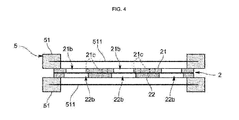
- the explosion proof device 5 includes protective covers 51 disposed at the outside of the pair of the electrodes 21 and 22, as shown in FIG. 4 , and prevents flames generated from a combustible gas, introduced into the fluid passage holes 21b and 22b, by plasma from propagating to the outside over the protective covers 51.
- each of the protective covers 51 of the explosion proof device 5 includes a metal mesh 511 disposed at the outside of the pair of the electrodes 21 and 22, and the metal mesh 511 has a wire diameter of approximately 1.5mm or less and an aperture ratio of approximately 30% or more.
- FIG. 7 is a graph illustrating distance dependency of negative ion number density measured by an air ion measurement instrument. From among active species generated by plasma, most of ions detected as air ions are ions having relatively long life and low activity, and in this test example, air ion concentration is used as an index using relations between an amount of generated active species and detected ions. As shown in FIG. 7 , the concentration of ions generated by the electrode unit 2 is highest at a position separated from the electrodes by a distance of several centimetres and tends to decrease as the distance from the electrodes increases.
- the distance at which the highest concentration of ions is detected depends on an air velocity or other environmental factors, but installation of the surface of the absorption member 4, within the distance at which the highest concentration of ions is detected, is important.
- the surface of the absorption member 4 needs to be installed at a position of more than the lowest ion number density (10,000/cm 3 ) required for a sterilizing capacity, which will be described later.
- deodorization using a combination of characteristics of the two deodorization methods i.e., deodorization due to absorption and deodorization due to active species
- deodorization due to absorption and deodorization due to active species reduces time taken to achieve deodorization and does not lower a deodorizing capacity even if the absorption member and the active species are repeatedly exposed to odors.
- saturation absorption which is a drawback of deodorization due to absorption continuously exhibits absorption performance through decomposition due to the active species.
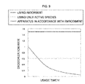
- deodorization efficiency of a case using only the absorbent is gradually lowered, as compared with the deodorization and sterilization apparatus 100 in accordance with the embodiment exhibiting uniform deodorization efficiency, as shown in FIG. 9 .
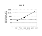
- FIG. 10 illustrates sterilization rates calculated after 12 hours, as a result of the test. It is understood from FIG. 10 that the sterilization rate depends on an amount of generated active species and nearly complete sterilization, e.g., a sterilization rate of 99%, is achieved in a condition of an air ion number density of about 10,000/ cm 3 or more.
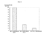
- FIG. 11 is a graph illustrating differences of sterilization rates among a case in which the absorbent member 4 is disposed at a position separated from the electrode unit 2 by a distance of 2cm (within the range of the above-described lowest ion number density), a case in which the absorbent member 4 is disposed at a position separated from the electrode unit 2 by a distance of 5cm (at the outside of the range of the above-described lowest ion number density), and a case in which the absorbent member 4 is not used.
- an object to be sterilized is colon bacilli
- active species are discharged under the condition that the absorption member 4 is disposed at the downstream of an air current from the electrodes, and then, the number of live bacteria on the surface of the absorption member 4 is measured.
- a sterilization rate of 99% is achieved after 6 hours
- a sterilization rate is remarkably reduced to 25%.
- a sterilization rate is further reduced to 10%. Accordingly, it is understood that the sterilization rate is remarkably improved by disposing the absorption member 4, and further, a sterilizing capacity depends on the amount of generated active species (the distance of the absorption member from the electrodes).
- FIG. 12 is a graph illustrating pulse width dependency of ion number density and ozone concentration.
- pulse width dependency of ion number density and ozone concentration is measured when only a pulse width is changed, while allowing a repetition frequency and a peak voltage value of a pulse to be uniformly maintained at approximately 1k.
- the ion number is measured and an ozone concentration is lowered at a pulse width of approximately 100 ⁇ s or less, and as a pulse width is decreased, the ion number is increased and the ozone concentration is decreased. Consequently, the ozone concentration may be suppressed by lowering the pulse to approximately 100 ⁇ s or less.
- a method of controlling balance between polarity of generated ions and an amount of the generated ions by applying bias of a DC component to applied voltage It is expected that kinds of active species optimal to decompose odor materials or absorbed to the absorption member 4 or floating bacteria are different. Therefore, increase of generation of active species most greatly contributing to deodorization or sterilization, by controlling the polarity or amount of ions, is effective in increasing the deodorization efficiency and sterilization rate.
- a ratio of generated ions may be controlled from among a condition in which a large amount of positive ions is generated, a condition in which a large amount of negative ions is generated, and a condition in which both positive ions and negative ions are generated.
- a contact area between plasma generated from the respective corresponding fluid passage holes 21b and 22b and a fluid is increased, thereby increasing an amount of generated active species.
- the absorption member 4 is disposed at the downstream of the fluid passage holes 21b and 22b, even if air having passed through the fluid passage holes 21b and 22b includes floating bacteria, which are not non-activated or odor materials which are not decomposed, the floating bacteria and the odor materials may be collected at one place through absorption via the absorption member 4 and high-efficiency sterilization and deodorization of the floating bacteria and the odor materials may be achieved by contact of the active species with the absorption member 4.
- the disclosure is not limited to the above embodiment of the present disclosure.
- a plurality of absorption members corresponding to one electrode may be disposed, or a plurality of plasma electrode units corresponding to one absorption member may be disposed.
- disposition of absorption members 4 having different absorbing capacities may be considered, as shown in FIGS. 14 and 15 .
- the plural absorption members 4 may be disposed in parallel, as shown in FIG. 14 , or be disposed in series, as shown in FIG. 15 . If the plural absorption members 4 are disposed in series, the absorption member 4 having an absorbing capacity optimized for absorption of large diameter particles and the absorption member having an absorbing capacity optimized for absorption of small diameter particles may be sequentially disposed from the plasma electrode unit 2.
- a rectifying plate may be provided at the upstream of the absorption members.
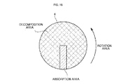
- a circular absorption member 4 may be provided to be rotated, as shown in FIG. 16 .
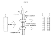
- the absorption member 4 is rotated once, floating bacteria and odor materials absorbed to the absorption member 4 moves between an absorption area which air containing floating bacteria and odor materials contacts, and a decomposition area in which sterilization and deodorization due to active species generated from the electrodes is executed, thus being sterilized.
- a sheet-type absorption member may be circulated by a circulation device so that an absorption area and a decomposition area are alternated.
- the absorption member may have various shapes, such as a rectangular shape and a polygonal shape, as seen from the top, in addition to a circular shape, as described in the above embodiment.
- the absorption member may be formed by retaining an absorbent on a mesh-type base, in addition to application of the absorbent to the flat plate.
- the absorbent may be retained on the metal meshes of the explosion proof device to form the absorption member, thereby simplifying the configuration of the apparatus.
- an ultraviolet lamp may be disposed adjacent to the absorption member and be used as a subsidiary unit for sterilization and deodorization, or the surface of the absorption member may be impregnated with a photocatalyst and an ultraviolet lamp may irradiate ultraviolet rays thereto.
- a path formation member 7 forming a path, through which plural fluid passage holes A to C communicate with each other such that the fluid passage hole A at one end of the path formed by the path formation member 7 faces the upstream in the air blowing direction and the fluid passage hole C at the other end of the path formed by the path formation member 7 faces the absorption member 4, may be provided, as shown in FIG. 17 .
- the path formation member 7 includes at least a first path formation part 71 installed at one electrode 21 of the plasma electrode unit 2 and a second path formation part 72 installed at the other electrode 22.
- the first path formation part 71 communicates the fluid passage holes A with the fluid passage hole B adjacent to the fluid passage hole A.
- the second path formation part 72 communicates the fluid passage holes B with the fluid passage hole C.
- An opening at the upstream of the fluid passage hole A and an opening at the downstream of the fluid passage hole C communicate with each other by the path formation member 71 and 72.
- the first path formation part 71 may communicate a through hole D formed on the electrode 21 with the fluid passage holes A and B as well as communicate the fluid passage hole A and the fluid passage hole B with each other
- the second path formation part 72 may communicate a through hole E formed on the electrode 22 with the fluid passage holes B and C as well as communicate the fluid passage hole B and the fluid passage hole C with each other.
- an absorbent may be provided on the inner surface of the path formation member 71 and 72 to absorb floating bacteria and odor materials in air. Thereby, the deodorizing capacity may be further improved.
- an introduction path formation member 8 to guide active species generated via the fluid passage holes 21 and 21b to the absorption member 4 may be provided between the plasma electrode unit 2 (the fluid passage holes 21 and 22b) and the absorption member 4.
- the introduction path formation member 8 has a retaining structure 8A to retain the active species.
- a part of the introduction path formation member 8 may be enlarged to have an increased cross-sectional area of a path to retain an air current, as shown in FIG. 19 .
- the introduction path formation member 8 having the retaining structure 8A elongates reaction time, as compared with a rectilinear path without a retaining part, thus increasing sterilization and deodorization efficiency.
- an eddy-shaped or maze-shaped introduction path may be provided to enlarge contact time between active species and odor materials/floating bacteria, thereby increasing sterilization and deodorization efficiency.
- an absorbent may be provided on the inner surface of the introduction path formation member to absorb floating bacteria and odor materials in air. Accordingly, the deodorizing capacity may be further improved.
- this embodiment illustrates that generation of ozone is reduced by applying pulse voltage
- ozone may be actively utilized.
- an ozone decomposition catalyst 9 is disposed adjacent to the absorption member 4 at the downstream of the plasma electrode unit 2. Accordingly, deodorization and sterilization effects due to ozone may be obtained, and thus, the apparatus may exhibit more effective deodorization and sterilization effects.
- the deodorization and sterilization apparatus in accordance with this embodiment may have a refresh function.
- a refresh function may be obtained by a heating device 10 to heat the absorption member 4, as shown in FIG. 21 .
- the heating device 10 includes, for example, a heater 10a to heat the absorption member 4 and a temperature regulator 10b to control the heater 10a.
- the heating device 10 periodically heats the absorption member 4, thereby re-discharging odor materials accumulated on the surface of the absorption member 4.
- the plasma electrode unit 2 supplies active species using the air blowing device 3, thereby achieving deodorization and sterilization of the re-discharged odor materials and floating bacteria. Accordingly, the absorbing capacity of the absorption member 4 may be recovered.
- the deodorization and sterilization apparatus 100 in accordance with this embodiment may be configured to individually exhibit an absorption function and a decomposition function.
- an absorption mode in which application of voltage to the plasma electrode unit 2 is stopped and air blown by the air blowing device 3 is executed simultaneously to allow the absorption member 4 to absorb floating bacteria or odor materials
- a decomposition mode in which voltage is applied to the plasma electrode unit 2 after the absorption mode to supply active species generated by plasma to the absorption member 4, may be provided to be switched.
- a sensor (not shown) may be provided at the downstream of the absorption member 4 so as to detect the absorbing capacity of the absorption member 4 and to execute mode switching between the absorption mode and the decomposition mode using a result of the detection. Further, feedback control of an amount of air blown by the air blowing device 3 may be carried out using the result of the detection.
- the air blowing device may be omitted if the deodorization and sterilization apparatus is used at a place where an air current is generated (for example, the inside of a tub of a washing machine, an air blowing unit of an electric fan, etc.).
- the plasma electrode unit may be disposed at the upstream side of the air current and the absorption member may be disposed at the downstream side of the air current.
- the apparatus is configured with a fluid flow direction, and the absorption member is located downstream of the electrodes along the fluid flow direction.
- the absorbent may be provided on the entirety or a portion of the air blowing device so that the air blowing device itself has an absorbing capacity.
- this embodiment illustrates the plural fluid passage holes 21b of the electrode 21 as having the same shape and the plural fluid passage holes 22b of the electrode 22 as having the same shape, the plural fluid passage holes 21b and the plural fluid passage holes 22b may have different shapes.
- this embodiment illustrates all of the fluid passage holes 21b of the electrode 21 as being larger or smaller than all of the fluid passage holes 22b of the electrode 22, some of the fluid passage holes 21b of the electrode 21 may be smaller than the fluid passage holes 22b of the electrode 22, and the remaining fluid passage holes 21b may be larger than the fluid passage holes 22b of the electrode 22.
- this embodiment illustrates the through holes as being formed on either of the electrodes 21 and 22, the through holes (half opening parts) may be formed on both the electrodes 21 and 22.
- the fluid passage holes 21b and 22b formed on the respective electrodes 21 and 22 may have various shapes, including, but not limited to, a shape having a tapered plane, a mortar shape or a bowl shape, i.e., a shape having a diameter decreased or increased from one opening to the other opening.
- fluid passage holes 21b and 22b may have various shapes other than a circle, including, but not limited to, shapes of an oval, a rectangle, a rectilinear slit, a concentric slit, a wave-shaped slit, a crescent moon, a comb, a honeycomb, or a star.
- a deodorization and sterilization apparatus and method in accordance with one embodiment of the present disclosure increases an amount of generated active species and collects floating bacteria or odor materials in air at one place such that the active species contact the collected floating bacteria or odor materials to achieve high-efficiency sterilization and deodorization.
Landscapes
- Engineering & Computer Science (AREA)
- Chemical & Material Sciences (AREA)
- Combustion & Propulsion (AREA)
- General Engineering & Computer Science (AREA)
- Mechanical Engineering (AREA)
- Health & Medical Sciences (AREA)
- Plasma & Fusion (AREA)
- Physics & Mathematics (AREA)
- Life Sciences & Earth Sciences (AREA)
- Animal Behavior & Ethology (AREA)
- Epidemiology (AREA)
- Veterinary Medicine (AREA)
- Public Health (AREA)
- General Health & Medical Sciences (AREA)
- Spectroscopy & Molecular Physics (AREA)
- Materials Engineering (AREA)
- Disinfection, Sterilisation Or Deodorisation Of Air (AREA)
- Treating Waste Gases (AREA)
Applications Claiming Priority (1)
| Application Number | Priority Date | Filing Date | Title |
|---|---|---|---|
| JP2010275509A JP2012120768A (ja) | 2010-12-10 | 2010-12-10 | 脱臭殺菌装置及び脱臭殺菌方法 |
Publications (3)
| Publication Number | Publication Date |
|---|---|
| EP2462955A2 true EP2462955A2 (fr) | 2012-06-13 |
| EP2462955A3 EP2462955A3 (fr) | 2012-08-22 |
| EP2462955B1 EP2462955B1 (fr) | 2020-02-26 |
Family
ID=45098937
Family Applications (1)
| Application Number | Title | Priority Date | Filing Date |
|---|---|---|---|
| EP11191821.5A Active EP2462955B1 (fr) | 2010-12-10 | 2011-12-02 | Appareil et procédé de désodorisation et de stérilisation |
Country Status (4)
| Country | Link |
|---|---|
| US (1) | US9717816B2 (fr) |
| EP (1) | EP2462955B1 (fr) |
| JP (1) | JP2012120768A (fr) |
| KR (1) | KR101893004B1 (fr) |
Cited By (6)
| Publication number | Priority date | Publication date | Assignee | Title |
|---|---|---|---|---|
| CN104756334A (zh) * | 2012-07-13 | 2015-07-01 | Sp技术有限公司 | 在电极上设有导电体突出部的介质阻挡放电式的等离子产生电极结构 |
| CN109821406A (zh) * | 2019-02-27 | 2019-05-31 | 天津市可帮化工产品有限公司 | 一种吸附-光解一体式废气处理设备 |
| CN109847577A (zh) * | 2019-02-27 | 2019-06-07 | 天津市可帮化工产品有限公司 | 一种等离子和炭吸附相结合的废气净化设备 |
| CN110935270A (zh) * | 2019-12-13 | 2020-03-31 | 西安润川环保科技有限公司 | 等离子光催化空气净化方法 |
| CN110935269A (zh) * | 2019-12-13 | 2020-03-31 | 西安润川环保科技有限公司 | 一种等离子光氧分解空气净化箱 |
| CN113680183A (zh) * | 2021-08-19 | 2021-11-23 | 四川大学 | 一种基于压电的自供电臭气处理及检测一体化设备 |
Families Citing this family (11)
| Publication number | Priority date | Publication date | Assignee | Title |
|---|---|---|---|---|
| JP6138441B2 (ja) * | 2011-09-21 | 2017-05-31 | 株式会社Nbcメッシュテック | 浮遊ウイルス除去ユニット |
| GB201313850D0 (en) * | 2013-08-02 | 2013-09-18 | Johnson Matthey Plc | Getter composition |
| WO2015058122A1 (fr) * | 2013-10-18 | 2015-04-23 | Thagard Selema Mededovic | Procédés et systèmes d'inactivation de bactéries dans un liquide à l'aide de plasmas à décharge électrique en phase liquide |
| KR101533396B1 (ko) * | 2014-03-27 | 2015-07-01 | 김두환 | 통풍 관로가 구비된 플라즈마 이온 발생 장치 |
| KR102818234B1 (ko) * | 2020-06-30 | 2025-06-10 | 캐논 가부시끼가이샤 | 제균 장치, 제균 방법, 활성 산소 공급 장치 및 활성 산소에 의한 처리 장치 |
| CN112503689B (zh) * | 2020-12-10 | 2022-03-25 | 广州金鹏环保工程有限公司 | 一种移动扫描式动态过滤静态杀菌消毒系统及方法 |
| CN112807472B (zh) * | 2021-01-14 | 2023-01-17 | 水木清研生态环保(山东)有限公司 | 医院中心吸引系统排气在线实时消毒灭菌除味的处理方法 |
| DE102022213109A1 (de) * | 2022-12-06 | 2024-06-06 | Robert Bosch Gesellschaft mit beschränkter Haftung | Raumluftfiltersystem |
| KR102712188B1 (ko) * | 2023-05-11 | 2024-09-30 | 주식회사 코드스테리 | 플라스마를 이용한 전자 데오드란트 기기 |
| EP4649967A1 (fr) * | 2023-03-09 | 2025-11-19 | Codesteri Inc. | Dispositif déodorant électronique utilisant du plasma |
| KR102827378B1 (ko) * | 2023-03-09 | 2025-07-01 | 주식회사 코드스테리 | 플라스마를 이용한 전자 데오드란트 기기 |
Citations (2)
| Publication number | Priority date | Publication date | Assignee | Title |
|---|---|---|---|---|
| JP2002224211A (ja) | 2000-05-18 | 2002-08-13 | Sharp Corp | 殺菌方法、イオン発生装置及び空気調節装置 |
| JP2003079714A (ja) | 2001-09-14 | 2003-03-18 | Matsushita Electric Works Ltd | 空気清浄機 |
Family Cites Families (15)
| Publication number | Priority date | Publication date | Assignee | Title |
|---|---|---|---|---|
| IT942698B (it) * | 1970-11-28 | 1973-04-02 | Buderus Eisenwerk | Filtro elettrostatico per aria ed altri gas |
| JPH11137654A (ja) * | 1997-11-07 | 1999-05-25 | Hitachi Ltd | エアクリーナ |
| JP2002204822A (ja) * | 2001-01-10 | 2002-07-23 | Ricoh Elemex Corp | 空気清浄機 |
| JP4371607B2 (ja) * | 2001-05-17 | 2009-11-25 | 株式会社東芝 | 光触媒反応装置 |
| TWI264313B (en) * | 2002-08-07 | 2006-10-21 | Access Business Group Int Llc | Nonthermal plasma air treatment system |
| JP2004350891A (ja) * | 2003-05-29 | 2004-12-16 | Matsushita Electric Ind Co Ltd | 浄化方法および浄化装置 |
| JP2005013554A (ja) * | 2003-06-27 | 2005-01-20 | Matsushita Electric Ind Co Ltd | 空気浄化装置 |
| WO2006013620A1 (fr) * | 2004-08-03 | 2006-02-09 | Mitsubishi Denki Kabushiki Kaisha | Purificateur d’air |
| JP2006164767A (ja) * | 2004-12-08 | 2006-06-22 | Sharp Corp | イオン発生装置 |
| US7740810B2 (en) * | 2004-12-14 | 2010-06-22 | Carrier Corporation | Photocatalyst protection |
| JP4251199B2 (ja) * | 2006-07-05 | 2009-04-08 | ダイキン工業株式会社 | 空気清浄機 |
| WO2008117817A1 (fr) * | 2007-03-28 | 2008-10-02 | Mitsubishi Electric Corporation | Echangeur thermique et appareil à cycle de réfrigération |
| JP4947807B2 (ja) * | 2007-09-09 | 2012-06-06 | 一男 清水 | プラズマを用いた流体浄化方法および流体浄化装置 |
| JP4460014B2 (ja) * | 2007-09-09 | 2010-05-12 | 一男 清水 | プラズマ電極 |
| FR2921867B1 (fr) * | 2007-10-08 | 2011-03-11 | Renault Sas | Systeme de chauffage/climatisation a regeneration de filtre pour vehicule automobile et procede de controle et filtre associes |
-
2010
- 2010-12-10 JP JP2010275509A patent/JP2012120768A/ja active Pending
-
2011
- 2011-11-02 KR KR1020110113203A patent/KR101893004B1/ko not_active Expired - Fee Related
- 2011-12-02 EP EP11191821.5A patent/EP2462955B1/fr active Active
- 2011-12-06 US US13/312,236 patent/US9717816B2/en active Active
Patent Citations (2)
| Publication number | Priority date | Publication date | Assignee | Title |
|---|---|---|---|---|
| JP2002224211A (ja) | 2000-05-18 | 2002-08-13 | Sharp Corp | 殺菌方法、イオン発生装置及び空気調節装置 |
| JP2003079714A (ja) | 2001-09-14 | 2003-03-18 | Matsushita Electric Works Ltd | 空気清浄機 |
Cited By (8)
| Publication number | Priority date | Publication date | Assignee | Title |
|---|---|---|---|---|
| CN104756334A (zh) * | 2012-07-13 | 2015-07-01 | Sp技术有限公司 | 在电极上设有导电体突出部的介质阻挡放电式的等离子产生电极结构 |
| CN104756334B (zh) * | 2012-07-13 | 2017-05-10 | Sp技术有限公司 | 在电极上设有导电体突出部的介质阻挡放电式的等离子产生电极结构 |
| CN109821406A (zh) * | 2019-02-27 | 2019-05-31 | 天津市可帮化工产品有限公司 | 一种吸附-光解一体式废气处理设备 |
| CN109847577A (zh) * | 2019-02-27 | 2019-06-07 | 天津市可帮化工产品有限公司 | 一种等离子和炭吸附相结合的废气净化设备 |
| CN110935270A (zh) * | 2019-12-13 | 2020-03-31 | 西安润川环保科技有限公司 | 等离子光催化空气净化方法 |
| CN110935269A (zh) * | 2019-12-13 | 2020-03-31 | 西安润川环保科技有限公司 | 一种等离子光氧分解空气净化箱 |
| CN113680183A (zh) * | 2021-08-19 | 2021-11-23 | 四川大学 | 一种基于压电的自供电臭气处理及检测一体化设备 |
| CN113680183B (zh) * | 2021-08-19 | 2022-08-26 | 四川大学 | 一种基于压电的自供电臭气处理及检测一体化设备 |
Also Published As
| Publication number | Publication date |
|---|---|
| US20120148445A1 (en) | 2012-06-14 |
| KR101893004B1 (ko) | 2018-08-29 |
| KR20120065224A (ko) | 2012-06-20 |
| EP2462955A3 (fr) | 2012-08-22 |
| EP2462955B1 (fr) | 2020-02-26 |
| JP2012120768A (ja) | 2012-06-28 |
| US9717816B2 (en) | 2017-08-01 |
Similar Documents
| Publication | Publication Date | Title |
|---|---|---|
| EP2462955B1 (fr) | Appareil et procédé de désodorisation et de stérilisation | |
| EP2462954B1 (fr) | Procédé et appareil de génération de plasma | |
| KR101500420B1 (ko) | 전극상에 도전체 돌출부를 갖는 유전체장벽 방전 방식의 플라즈마 발생 전극 구조체 | |
| KR101601654B1 (ko) | 플라즈마 발생 장치, 플라즈마 발생 방법, 및 오존 발생 억제 방법 | |
| US20150359922A1 (en) | Air purifying apparatus using ultra violet light emitting diode | |
| GB2494296A (en) | Photocatalytic oxidising assembly | |
| CA2783866A1 (fr) | Cellule d'electrofiltre avec module corona amovible | |
| JP2008289801A (ja) | ガス浄化装置 | |
| JPWO2013051730A1 (ja) | プラズマ発生装置 | |
| KR100949797B1 (ko) | 플라스마를 이용한 탈취 및 살균장치 | |
| EP2638959A1 (fr) | Générateur de plasma et procédé de génération de plasma | |
| JP3445468B2 (ja) | 空気清浄装置及び同装置用の集塵電極 | |
| JP3717033B2 (ja) | 空気清浄化装置及び空気清浄化方法 | |
| JP2006097982A (ja) | レンジフード | |
| JP2006167190A (ja) | 空気浄化装置 | |
| JP2009233106A (ja) | 脱臭装置 | |
| JP2008014527A (ja) | 空気調和機 | |
| JP2012075487A (ja) | 除菌装置及びこの除菌装置を備えた調湿装置 | |
| JP2007268165A (ja) | 脱臭装置の制御方法 | |
| CN223760153U (zh) | 一种杀菌净味功能模块及冰箱 | |
| JP2008228831A (ja) | 脱臭装置 | |
| JP2009165546A (ja) | 脱臭装置 | |
| KR20200030241A (ko) | 이온발생기를 이용하는 공기청정기 | |
| JP2008173296A (ja) | 脱臭装置 | |
| CN120212681A (zh) | 冰箱 |
Legal Events
| Date | Code | Title | Description |
|---|---|---|---|
| PUAI | Public reference made under article 153(3) epc to a published international application that has entered the european phase |
Free format text: ORIGINAL CODE: 0009012 |
|
| AK | Designated contracting states |
Kind code of ref document: A2 Designated state(s): AL AT BE BG CH CY CZ DE DK EE ES FI FR GB GR HR HU IE IS IT LI LT LU LV MC MK MT NL NO PL PT RO RS SE SI SK SM TR |
|
| AX | Request for extension of the european patent |
Extension state: BA ME |
|
| PUAL | Search report despatched |
Free format text: ORIGINAL CODE: 0009013 |
|
| AK | Designated contracting states |
Kind code of ref document: A3 Designated state(s): AL AT BE BG CH CY CZ DE DK EE ES FI FR GB GR HR HU IE IS IT LI LT LU LV MC MK MT NL NO PL PT RO RS SE SI SK SM TR |
|
| AX | Request for extension of the european patent |
Extension state: BA ME |
|
| RIC1 | Information provided on ipc code assigned before grant |
Ipc: B01J 19/08 20060101ALI20120716BHEP Ipc: F24F 3/16 20060101ALI20120716BHEP Ipc: B01D 53/32 20060101ALI20120716BHEP Ipc: A61L 9/22 20060101AFI20120716BHEP Ipc: H05H 1/24 20060101ALI20120716BHEP |
|
| RAP1 | Party data changed (applicant data changed or rights of an application transferred) |
Owner name: SAMSUNG ELECTRONICS CO., LTD. |
|
| 17P | Request for examination filed |
Effective date: 20130222 |
|
| 17Q | First examination report despatched |
Effective date: 20160525 |
|
| STAA | Information on the status of an ep patent application or granted ep patent |
Free format text: STATUS: EXAMINATION IS IN PROGRESS |
|
| GRAP | Despatch of communication of intention to grant a patent |
Free format text: ORIGINAL CODE: EPIDOSNIGR1 |
|
| STAA | Information on the status of an ep patent application or granted ep patent |
Free format text: STATUS: GRANT OF PATENT IS INTENDED |
|
| INTG | Intention to grant announced |
Effective date: 20190723 |
|
| GRAJ | Information related to disapproval of communication of intention to grant by the applicant or resumption of examination proceedings by the epo deleted |
Free format text: ORIGINAL CODE: EPIDOSDIGR1 |
|
| STAA | Information on the status of an ep patent application or granted ep patent |
Free format text: STATUS: EXAMINATION IS IN PROGRESS |
|
| INTC | Intention to grant announced (deleted) | ||
| GRAR | Information related to intention to grant a patent recorded |
Free format text: ORIGINAL CODE: EPIDOSNIGR71 |
|
| GRAS | Grant fee paid |
Free format text: ORIGINAL CODE: EPIDOSNIGR3 |
|
| STAA | Information on the status of an ep patent application or granted ep patent |
Free format text: STATUS: GRANT OF PATENT IS INTENDED |
|
| GRAA | (expected) grant |
Free format text: ORIGINAL CODE: 0009210 |
|
| STAA | Information on the status of an ep patent application or granted ep patent |
Free format text: STATUS: THE PATENT HAS BEEN GRANTED |
|
| AK | Designated contracting states |
Kind code of ref document: B1 Designated state(s): AL AT BE BG CH CY CZ DE DK EE ES FI FR GB GR HR HU IE IS IT LI LT LU LV MC MK MT NL NO PL PT RO RS SE SI SK SM TR |
|
| INTG | Intention to grant announced |
Effective date: 20200122 |
|
| REG | Reference to a national code |
Ref country code: GB Ref legal event code: FG4D |
|
| REG | Reference to a national code |
Ref country code: CH Ref legal event code: EP |
|
| REG | Reference to a national code |
Ref country code: DE Ref legal event code: R096 Ref document number: 602011065193 Country of ref document: DE |
|
| REG | Reference to a national code |
Ref country code: AT Ref legal event code: REF Ref document number: 1236848 Country of ref document: AT Kind code of ref document: T Effective date: 20200315 |
|
| REG | Reference to a national code |
Ref country code: IE Ref legal event code: FG4D |
|
| PG25 | Lapsed in a contracting state [announced via postgrant information from national office to epo] |
Ref country code: RS Free format text: LAPSE BECAUSE OF FAILURE TO SUBMIT A TRANSLATION OF THE DESCRIPTION OR TO PAY THE FEE WITHIN THE PRESCRIBED TIME-LIMIT Effective date: 20200226 Ref country code: FI Free format text: LAPSE BECAUSE OF FAILURE TO SUBMIT A TRANSLATION OF THE DESCRIPTION OR TO PAY THE FEE WITHIN THE PRESCRIBED TIME-LIMIT Effective date: 20200226 Ref country code: NO Free format text: LAPSE BECAUSE OF FAILURE TO SUBMIT A TRANSLATION OF THE DESCRIPTION OR TO PAY THE FEE WITHIN THE PRESCRIBED TIME-LIMIT Effective date: 20200526 |
|
| REG | Reference to a national code |
Ref country code: NL Ref legal event code: MP Effective date: 20200226 |
|
| REG | Reference to a national code |
Ref country code: LT Ref legal event code: MG4D |
|
| PG25 | Lapsed in a contracting state [announced via postgrant information from national office to epo] |
Ref country code: HR Free format text: LAPSE BECAUSE OF FAILURE TO SUBMIT A TRANSLATION OF THE DESCRIPTION OR TO PAY THE FEE WITHIN THE PRESCRIBED TIME-LIMIT Effective date: 20200226 Ref country code: SE Free format text: LAPSE BECAUSE OF FAILURE TO SUBMIT A TRANSLATION OF THE DESCRIPTION OR TO PAY THE FEE WITHIN THE PRESCRIBED TIME-LIMIT Effective date: 20200226 Ref country code: LV Free format text: LAPSE BECAUSE OF FAILURE TO SUBMIT A TRANSLATION OF THE DESCRIPTION OR TO PAY THE FEE WITHIN THE PRESCRIBED TIME-LIMIT Effective date: 20200226 Ref country code: GR Free format text: LAPSE BECAUSE OF FAILURE TO SUBMIT A TRANSLATION OF THE DESCRIPTION OR TO PAY THE FEE WITHIN THE PRESCRIBED TIME-LIMIT Effective date: 20200527 Ref country code: IS Free format text: LAPSE BECAUSE OF FAILURE TO SUBMIT A TRANSLATION OF THE DESCRIPTION OR TO PAY THE FEE WITHIN THE PRESCRIBED TIME-LIMIT Effective date: 20200626 Ref country code: BG Free format text: LAPSE BECAUSE OF FAILURE TO SUBMIT A TRANSLATION OF THE DESCRIPTION OR TO PAY THE FEE WITHIN THE PRESCRIBED TIME-LIMIT Effective date: 20200526 |
|
| PG25 | Lapsed in a contracting state [announced via postgrant information from national office to epo] |
Ref country code: NL Free format text: LAPSE BECAUSE OF FAILURE TO SUBMIT A TRANSLATION OF THE DESCRIPTION OR TO PAY THE FEE WITHIN THE PRESCRIBED TIME-LIMIT Effective date: 20200226 |
|
| PG25 | Lapsed in a contracting state [announced via postgrant information from national office to epo] |
Ref country code: SK Free format text: LAPSE BECAUSE OF FAILURE TO SUBMIT A TRANSLATION OF THE DESCRIPTION OR TO PAY THE FEE WITHIN THE PRESCRIBED TIME-LIMIT Effective date: 20200226 Ref country code: RO Free format text: LAPSE BECAUSE OF FAILURE TO SUBMIT A TRANSLATION OF THE DESCRIPTION OR TO PAY THE FEE WITHIN THE PRESCRIBED TIME-LIMIT Effective date: 20200226 Ref country code: SM Free format text: LAPSE BECAUSE OF FAILURE TO SUBMIT A TRANSLATION OF THE DESCRIPTION OR TO PAY THE FEE WITHIN THE PRESCRIBED TIME-LIMIT Effective date: 20200226 Ref country code: CZ Free format text: LAPSE BECAUSE OF FAILURE TO SUBMIT A TRANSLATION OF THE DESCRIPTION OR TO PAY THE FEE WITHIN THE PRESCRIBED TIME-LIMIT Effective date: 20200226 Ref country code: EE Free format text: LAPSE BECAUSE OF FAILURE TO SUBMIT A TRANSLATION OF THE DESCRIPTION OR TO PAY THE FEE WITHIN THE PRESCRIBED TIME-LIMIT Effective date: 20200226 Ref country code: LT Free format text: LAPSE BECAUSE OF FAILURE TO SUBMIT A TRANSLATION OF THE DESCRIPTION OR TO PAY THE FEE WITHIN THE PRESCRIBED TIME-LIMIT Effective date: 20200226 Ref country code: PT Free format text: LAPSE BECAUSE OF FAILURE TO SUBMIT A TRANSLATION OF THE DESCRIPTION OR TO PAY THE FEE WITHIN THE PRESCRIBED TIME-LIMIT Effective date: 20200719 Ref country code: DK Free format text: LAPSE BECAUSE OF FAILURE TO SUBMIT A TRANSLATION OF THE DESCRIPTION OR TO PAY THE FEE WITHIN THE PRESCRIBED TIME-LIMIT Effective date: 20200226 Ref country code: ES Free format text: LAPSE BECAUSE OF FAILURE TO SUBMIT A TRANSLATION OF THE DESCRIPTION OR TO PAY THE FEE WITHIN THE PRESCRIBED TIME-LIMIT Effective date: 20200226 |
|
| REG | Reference to a national code |
Ref country code: AT Ref legal event code: MK05 Ref document number: 1236848 Country of ref document: AT Kind code of ref document: T Effective date: 20200226 |
|
| REG | Reference to a national code |
Ref country code: DE Ref legal event code: R097 Ref document number: 602011065193 Country of ref document: DE |
|
| PLBE | No opposition filed within time limit |
Free format text: ORIGINAL CODE: 0009261 |
|
| STAA | Information on the status of an ep patent application or granted ep patent |
Free format text: STATUS: NO OPPOSITION FILED WITHIN TIME LIMIT |
|
| PG25 | Lapsed in a contracting state [announced via postgrant information from national office to epo] |
Ref country code: AT Free format text: LAPSE BECAUSE OF FAILURE TO SUBMIT A TRANSLATION OF THE DESCRIPTION OR TO PAY THE FEE WITHIN THE PRESCRIBED TIME-LIMIT Effective date: 20200226 Ref country code: IT Free format text: LAPSE BECAUSE OF FAILURE TO SUBMIT A TRANSLATION OF THE DESCRIPTION OR TO PAY THE FEE WITHIN THE PRESCRIBED TIME-LIMIT Effective date: 20200226 |
|
| 26N | No opposition filed |
Effective date: 20201127 |
|
| PG25 | Lapsed in a contracting state [announced via postgrant information from national office to epo] |
Ref country code: SI Free format text: LAPSE BECAUSE OF FAILURE TO SUBMIT A TRANSLATION OF THE DESCRIPTION OR TO PAY THE FEE WITHIN THE PRESCRIBED TIME-LIMIT Effective date: 20200226 Ref country code: PL Free format text: LAPSE BECAUSE OF FAILURE TO SUBMIT A TRANSLATION OF THE DESCRIPTION OR TO PAY THE FEE WITHIN THE PRESCRIBED TIME-LIMIT Effective date: 20200226 |
|
| REG | Reference to a national code |
Ref country code: CH Ref legal event code: PL |
|
| PG25 | Lapsed in a contracting state [announced via postgrant information from national office to epo] |
Ref country code: MC Free format text: LAPSE BECAUSE OF FAILURE TO SUBMIT A TRANSLATION OF THE DESCRIPTION OR TO PAY THE FEE WITHIN THE PRESCRIBED TIME-LIMIT Effective date: 20200226 |
|
| REG | Reference to a national code |
Ref country code: BE Ref legal event code: MM Effective date: 20201231 |
|
| PG25 | Lapsed in a contracting state [announced via postgrant information from national office to epo] |
Ref country code: FR Free format text: LAPSE BECAUSE OF NON-PAYMENT OF DUE FEES Effective date: 20201231 Ref country code: LU Free format text: LAPSE BECAUSE OF NON-PAYMENT OF DUE FEES Effective date: 20201202 Ref country code: IE Free format text: LAPSE BECAUSE OF NON-PAYMENT OF DUE FEES Effective date: 20201202 |
|
| PG25 | Lapsed in a contracting state [announced via postgrant information from national office to epo] |
Ref country code: CH Free format text: LAPSE BECAUSE OF NON-PAYMENT OF DUE FEES Effective date: 20201231 Ref country code: LI Free format text: LAPSE BECAUSE OF NON-PAYMENT OF DUE FEES Effective date: 20201231 |
|
| PGFP | Annual fee paid to national office [announced via postgrant information from national office to epo] |
Ref country code: GB Payment date: 20211122 Year of fee payment: 11 Ref country code: DE Payment date: 20211122 Year of fee payment: 11 |
|
| PG25 | Lapsed in a contracting state [announced via postgrant information from national office to epo] |
Ref country code: TR Free format text: LAPSE BECAUSE OF FAILURE TO SUBMIT A TRANSLATION OF THE DESCRIPTION OR TO PAY THE FEE WITHIN THE PRESCRIBED TIME-LIMIT Effective date: 20200226 Ref country code: MT Free format text: LAPSE BECAUSE OF FAILURE TO SUBMIT A TRANSLATION OF THE DESCRIPTION OR TO PAY THE FEE WITHIN THE PRESCRIBED TIME-LIMIT Effective date: 20200226 Ref country code: CY Free format text: LAPSE BECAUSE OF FAILURE TO SUBMIT A TRANSLATION OF THE DESCRIPTION OR TO PAY THE FEE WITHIN THE PRESCRIBED TIME-LIMIT Effective date: 20200226 |
|
| PG25 | Lapsed in a contracting state [announced via postgrant information from national office to epo] |
Ref country code: MK Free format text: LAPSE BECAUSE OF FAILURE TO SUBMIT A TRANSLATION OF THE DESCRIPTION OR TO PAY THE FEE WITHIN THE PRESCRIBED TIME-LIMIT Effective date: 20200226 Ref country code: AL Free format text: LAPSE BECAUSE OF FAILURE TO SUBMIT A TRANSLATION OF THE DESCRIPTION OR TO PAY THE FEE WITHIN THE PRESCRIBED TIME-LIMIT Effective date: 20200226 |
|
| PG25 | Lapsed in a contracting state [announced via postgrant information from national office to epo] |
Ref country code: BE Free format text: LAPSE BECAUSE OF NON-PAYMENT OF DUE FEES Effective date: 20201231 |
|
| REG | Reference to a national code |
Ref country code: DE Ref legal event code: R119 Ref document number: 602011065193 Country of ref document: DE |
|
| GBPC | Gb: european patent ceased through non-payment of renewal fee |
Effective date: 20221202 |
|
| PG25 | Lapsed in a contracting state [announced via postgrant information from national office to epo] |
Ref country code: GB Free format text: LAPSE BECAUSE OF NON-PAYMENT OF DUE FEES Effective date: 20221202 Ref country code: DE Free format text: LAPSE BECAUSE OF NON-PAYMENT OF DUE FEES Effective date: 20230701 |