EP2463059A2 - Arbeitssparende Zange - Google Patents
Arbeitssparende Zange Download PDFInfo
- Publication number
- EP2463059A2 EP2463059A2 EP11009594A EP11009594A EP2463059A2 EP 2463059 A2 EP2463059 A2 EP 2463059A2 EP 11009594 A EP11009594 A EP 11009594A EP 11009594 A EP11009594 A EP 11009594A EP 2463059 A2 EP2463059 A2 EP 2463059A2
- Authority
- EP
- European Patent Office
- Prior art keywords
- working portion
- combining member
- combining
- handle
- jaw
- Prior art date
- Legal status (The legal status is an assumption and is not a legal conclusion. Google has not performed a legal analysis and makes no representation as to the accuracy of the status listed.)
- Withdrawn
Links
Images



Classifications
-
- B—PERFORMING OPERATIONS; TRANSPORTING
- B25—HAND TOOLS; PORTABLE POWER-DRIVEN TOOLS; MANIPULATORS
- B25B—TOOLS OR BENCH DEVICES NOT OTHERWISE PROVIDED FOR, FOR FASTENING, CONNECTING, DISENGAGING, OR HOLDING
- B25B7/00—Pliers; Other hand-held gripping tools with jaws on pivoted limbs; Details applicable generally to pivoted-limb hand tools
- B25B7/12—Pliers; Other hand-held gripping tools with jaws on pivoted limbs; Details applicable generally to pivoted-limb hand tools involving special transmission means between the handles and the jaws, e.g. toggle levers, gears
Definitions
- This invention relates to pliers, particularly to laborsaving pliers.
- Conventional pliers contain two opposite pliers portions respectively formed with a working end and a grasping end. After the two pliers portions are intersected with each other and pivotally combined together to make up a pair of pliers. Then the two grasping ends of the pliers can be opened or closed to carry out movement of opening and closing of the two working ends. Therefore, the working ends of the pliers can be operated in different modes for attaining different functions, such as cutting, compression and the like in accordance with practical needs. Based on the principle of a lever, the working ends of the pliers are regarded as resistive force arms while the grasping ends regarded as motive force arms. If the working ends need greater force, the grasping ends must be longer accordingly.
- a floating fulcrum is provided on a working handle, and through the floating fulcrum, the force arms of the handle can be lengthened and the force applied to the working ends can be increased.
- the objective of this invention is to offer laborsaving pliers mainly containing a first main body 10, a second working portion 20 and a second handle 30.
- the first main body 10 is composed of a first handle 11 at a lower end and a first working portion 12 positioned opposite to the topside of the first handle 11.
- the first working portion 12 is provided thereon with a first combining member 121 having one side of its upper end formed with a first jaw 123, and an arcuate slide groove 13 is bored between the first combining member 121 and the first handle 11.
- the second working portion 20 relative to the first working portion 12 is disposed with a second combining member 21 to be combined with the first combining member 121 to enable the first working portion 12 and the second working portion 20 to produce movement of relative rotation.
- the second working portion 20 has one side of its upper end formed with a second jaw 22 opposite to the first jaw 123, and the second combining member 21 of the second working portion 20 has a lower side fixed with a combining rod 23.
- the second handle 30 has an upper end secured with a sliding rod 31 to slidably move in the arcuate slide groove 13 and has a slide-joint groove 32 bored at a location adjacent to the center for the combining rod 23 to slide therein.
- the laborsaving pliers in the present invention is provided with floating fulcrums to have the sliding rod 31 sliding in the arcuate slide groove 13 and have the combining rod 23 sliding in the slide-joint groove 32, able to increase the length of the force arms and relatively increase the force between the first jaw 123 and the second jaw 22.
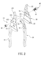
- a first preferred embodiment of laborsaving pliers in the present invention includes a first main body 10, a second working portion 20, a second handle 30 and a fixing member 50 as main components combined together.
- the first main body 10 has its lower end formed with a first handle 11 having its upper end formed with a first working portion 12 provided thereon with a first combining member 121 with a disc surface bored with a through hole 122 in the center.
- the first working portion 12 has one side of its upper end disposed with a first jaw 123, and an arcuate slide groove 13 is bored at a location between the first combining member 121 and the first handle 11.
- the second working portion 20 relative to the first working portion 12 is provided with a second combining member 21 to be coincided with the first combining member 121.
- the second combination 21 is also a disc surface opposite to the first combining member 121 and is bored with a through hole 211 in the center to enable the first working portion 12 and the second working portion 20 to produce movement of relative rotation.
- the second working portion 20 has one side of its upper end formed with a second jaw 22 to correspond with the first jaw 123.
- the first jaw 123 and the second jaw 22 can be driven to move close to each other or keep away from each other at a great distance via mutual rotation of the first working portion 12 and the second working portion 20.
- the second combining member 21 of the second working portion 20 is fixed with a combining rod 23 protruding out at a lower side.
- the second handle 30 is a shank having its upper end provided with a protruding sliding rod 31 slidably moving in the arcuate slide groove 13 and is disposed with a slide-joint groove 32 at a location adjacent to the center for the combining rod 23 of the second combination portion 21 to slide therein.
- the fixing member 40 is composed of a bolt 41 and a nut 42 and can be a rivet. After the bolt 41 is inserted through the through hole 122 of the first combining member 121 and the through hole 211 of the second combining member 21, the end of the bolt 41 is locked with the nut 42.
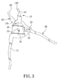
- the first handle 11 and the second handle 30 are respectively and oppositely moved outward and at this time, the sliding rod 31 is positioned at the lower side of the arcuate slide groove 13, and the combining rod 23 also comes to the lower side of the slide-joint groove 32, thus forming a maximum interval between the first jaw 123 and the second jaw 22.
- Such a design is able to enlarge the opening of the first jaw 123 and the second jaw 22 for receiving a work piece with a greater breadth.
- the force applied to both the first handle 11 and the second handle 30 can be greatly added, and thus the force applied to a work piece by both the first jaw 123 and the second jaw 22 will be increased not a little.
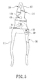
- a second preferred embodiment of laborsaving pliers in the present invention has almost the same structure as that of the first preferred embodiment, except that a position-limiting groove 131 is additionally provided at the upper end of the arcuate slide groove 13 for restrictedly positioning the sliding rod 31.
- the sliding rod 31 can be restrictedly positioned in the position-limiting groove 131 and it only needs a force arm produced between the combination rod 23 and the fixing member 40.
Landscapes
- Engineering & Computer Science (AREA)
- Mechanical Engineering (AREA)
- Gripping Jigs, Holding Jigs, And Positioning Jigs (AREA)
Applications Claiming Priority (1)
| Application Number | Priority Date | Filing Date | Title |
|---|---|---|---|
| TW099224119U TWM417996U (en) | 2010-12-13 | 2010-12-13 | Labor saving cutting plier |
Publications (1)
| Publication Number | Publication Date |
|---|---|
| EP2463059A2 true EP2463059A2 (de) | 2012-06-13 |
Family
ID=45218183
Family Applications (1)
| Application Number | Title | Priority Date | Filing Date |
|---|---|---|---|
| EP11009594A Withdrawn EP2463059A2 (de) | 2010-12-13 | 2011-12-05 | Arbeitssparende Zange |
Country Status (3)
| Country | Link |
|---|---|
| US (1) | US20120144963A1 (de) |
| EP (1) | EP2463059A2 (de) |
| TW (1) | TWM417996U (de) |
Cited By (1)
| Publication number | Priority date | Publication date | Assignee | Title |
|---|---|---|---|---|
| EP3284560A4 (de) * | 2015-04-15 | 2019-02-20 | Hangzhou Great Star Tools Co., Ltd. | Handbetriebenes werkzeug |
Families Citing this family (9)
| Publication number | Priority date | Publication date | Assignee | Title |
|---|---|---|---|---|
| USD753455S1 (en) | 2014-07-30 | 2016-04-12 | Milwaukee Electric Tool Corporation | Cutting tool |
| CN106141947B (zh) * | 2015-04-15 | 2025-02-11 | 杭州巨星工具有限公司 | 一种手动工具 |
| TWI615248B (zh) * | 2016-05-03 | 2018-02-21 | 可自動夾固之鉗子 | |
| WO2018161325A1 (zh) * | 2017-03-09 | 2018-09-13 | 杭州巨星科技股份有限公司 | 一种张合装置 |
| CN107685178A (zh) * | 2017-09-27 | 2018-02-13 | 威海市威力高档工具有限公司 | 具有三杠杆省力功能的铁皮剪 |
| US10493601B2 (en) * | 2018-01-17 | 2019-12-03 | Zhang Ruqian | Compound pliers |
| TWI717949B (zh) * | 2019-12-24 | 2021-02-01 | 游再順 | 剪鉗 |
| CN111438711A (zh) * | 2020-05-12 | 2020-07-24 | 张家港威尔斯五金科技有限公司 | 一种可变形的曲柄斜口钳 |
| JP7203801B2 (ja) * | 2020-11-06 | 2023-01-13 | 横河電機株式会社 | ハンドグリップ機構、駆動機構及び空気ポンプ |
Family Cites Families (5)
| Publication number | Priority date | Publication date | Assignee | Title |
|---|---|---|---|---|
| US1227372A (en) * | 1916-10-06 | 1917-05-22 | Yancy M Bledsoe | Wrench. |
| US1836473A (en) * | 1930-05-26 | 1931-12-15 | Kob Henry Howard | Wrench |
| US3685097A (en) * | 1970-08-03 | 1972-08-22 | Scott Mach Dev Corp | Clam opener tools |
| US5033338A (en) * | 1990-03-21 | 1991-07-23 | Ford Jr Vernon J G | Self-locking device |
| US6532847B2 (en) * | 1999-08-02 | 2003-03-18 | Mou-Tang Liou | Force-saving pliers |
-
2010
- 2010-12-13 TW TW099224119U patent/TWM417996U/zh not_active IP Right Cessation
-
2011
- 2011-12-05 EP EP11009594A patent/EP2463059A2/de not_active Withdrawn
- 2011-12-07 US US13/313,590 patent/US20120144963A1/en not_active Abandoned
Non-Patent Citations (1)
| Title |
|---|
| None |
Cited By (2)
| Publication number | Priority date | Publication date | Assignee | Title |
|---|---|---|---|---|
| EP3284560A4 (de) * | 2015-04-15 | 2019-02-20 | Hangzhou Great Star Tools Co., Ltd. | Handbetriebenes werkzeug |
| US10940576B2 (en) | 2015-04-15 | 2021-03-09 | Hangzhou Great Star Tools Co., Ltd. | Hand tool |
Also Published As
| Publication number | Publication date |
|---|---|
| TWM417996U (en) | 2011-12-11 |
| US20120144963A1 (en) | 2012-06-14 |
Similar Documents
| Publication | Publication Date | Title |
|---|---|---|
| EP2463059A2 (de) | Arbeitssparende Zange | |
| US8656813B1 (en) | Locking pliers | |
| US9027447B2 (en) | Locking pliers with handle locking mechanism | |
| US20090007733A1 (en) | Clamping and cutting apparatus with adjustable head | |
| US20170215346A1 (en) | Control Device of Cutting Tool | |
| KR870009821A (ko) | 절첩식 연장 | |
| TWM418532U (en) | Improved structure of flower shears | |
| US20080295341A1 (en) | Hand operated cutting tool | |
| US20120096994A1 (en) | Hand tool with compound leverage mechanism | |
| EP0893209A1 (de) | Aufklappbares Werkzeug wie aufklappbarem Messer | |
| CN103711393B (zh) | 一种可锁定缓冲开关位置的铰链装置 | |
| TWI633834B (zh) | Gardening shears that increase structural strength | |
| US20080173143A1 (en) | Universal Pliers | |
| US1850664A (en) | Pliers | |
| US9848539B2 (en) | Control device of cutting tool | |
| US20110296694A1 (en) | Clipper | |
| JP3159703U (ja) | 鋏 | |
| CN108262699A (zh) | 一种错位锁紧和释放的棘轮机构和一种棘轮夹 | |
| CN206605394U (zh) | 一种张合装置 | |
| JP6583835B2 (ja) | ロック機能付きピンセット | |
| CN108568759A (zh) | 一种张合装置 | |
| US20170157747A1 (en) | Hand tool | |
| US7044032B2 (en) | Locking pliers and method of use | |
| US20060117570A1 (en) | Utility Knife with Cam Clamp Means | |
| GB2498829A (en) | Garden shears having a gear rotatable in a toothed slot |
Legal Events
| Date | Code | Title | Description |
|---|---|---|---|
| PUAI | Public reference made under article 153(3) epc to a published international application that has entered the european phase |
Free format text: ORIGINAL CODE: 0009012 |
|
| AK | Designated contracting states |
Kind code of ref document: A2 Designated state(s): AL AT BE BG CH CY CZ DE DK EE ES FI FR GB GR HR HU IE IS IT LI LT LU LV MC MK MT NL NO PL PT RO RS SE SI SK SM TR |
|
| AX | Request for extension of the european patent |
Extension state: BA ME |
|
| STAA | Information on the status of an ep patent application or granted ep patent |
Free format text: STATUS: THE APPLICATION IS DEEMED TO BE WITHDRAWN |
|
| 18D | Application deemed to be withdrawn |
Effective date: 20140701 |