EP2463183A2 - Dispositif de positionnement de pièce et système de production l'utilisant - Google Patents
Dispositif de positionnement de pièce et système de production l'utilisant Download PDFInfo
- Publication number
- EP2463183A2 EP2463183A2 EP11192500A EP11192500A EP2463183A2 EP 2463183 A2 EP2463183 A2 EP 2463183A2 EP 11192500 A EP11192500 A EP 11192500A EP 11192500 A EP11192500 A EP 11192500A EP 2463183 A2 EP2463183 A2 EP 2463183A2
- Authority
- EP
- European Patent Office
- Prior art keywords
- workpiece
- axis
- workpiece positioning
- moving
- moving unit
- Prior art date
- Legal status (The legal status is an assumption and is not a legal conclusion. Google has not performed a legal analysis and makes no representation as to the accuracy of the status listed.)
- Granted
Links
Images


Classifications
-
- B—PERFORMING OPERATIONS; TRANSPORTING
- B62—LAND VEHICLES FOR TRAVELLING OTHERWISE THAN ON RAILS
- B62D—MOTOR VEHICLES; TRAILERS
- B62D65/00—Designing, manufacturing, e.g. assembling, facilitating disassembly, or structurally modifying motor vehicles or trailers, not otherwise provided for
- B62D65/02—Joining sub-units or components to, or positioning sub-units or components with respect to, body shell or other sub-units or components
- B62D65/024—Positioning of sub-units or components with respect to body shell or other sub-units or components
-
- B—PERFORMING OPERATIONS; TRANSPORTING
- B23—MACHINE TOOLS; METAL-WORKING NOT OTHERWISE PROVIDED FOR
- B23P—METAL-WORKING NOT OTHERWISE PROVIDED FOR; COMBINED OPERATIONS; UNIVERSAL MACHINE TOOLS
- B23P19/00—Machines for simply fitting together or separating metal parts or objects, or metal and non-metal parts, whether or not involving some deformation; Tools or devices therefor so far as not provided for in other classes
-
- B—PERFORMING OPERATIONS; TRANSPORTING
- B23—MACHINE TOOLS; METAL-WORKING NOT OTHERWISE PROVIDED FOR
- B23P—METAL-WORKING NOT OTHERWISE PROVIDED FOR; COMBINED OPERATIONS; UNIVERSAL MACHINE TOOLS
- B23P21/00—Machines for assembling a multiplicity of different parts to compose units, with or without preceding or subsequent working of such parts, e.g. with program control
-
- B—PERFORMING OPERATIONS; TRANSPORTING
- B62—LAND VEHICLES FOR TRAVELLING OTHERWISE THAN ON RAILS
- B62D—MOTOR VEHICLES; TRAILERS
- B62D65/00—Designing, manufacturing, e.g. assembling, facilitating disassembly, or structurally modifying motor vehicles or trailers, not otherwise provided for
- B62D65/02—Joining sub-units or components to, or positioning sub-units or components with respect to, body shell or other sub-units or components
- B62D65/18—Transportation, conveyor or haulage systems specially adapted for motor vehicle or trailer assembly lines
-
- Y—GENERAL TAGGING OF NEW TECHNOLOGICAL DEVELOPMENTS; GENERAL TAGGING OF CROSS-SECTIONAL TECHNOLOGIES SPANNING OVER SEVERAL SECTIONS OF THE IPC; TECHNICAL SUBJECTS COVERED BY FORMER USPC CROSS-REFERENCE ART COLLECTIONS [XRACs] AND DIGESTS
- Y10—TECHNICAL SUBJECTS COVERED BY FORMER USPC
- Y10T—TECHNICAL SUBJECTS COVERED BY FORMER US CLASSIFICATION
- Y10T29/00—Metal working
- Y10T29/53—Means to assemble or disassemble
- Y10T29/534—Multiple station assembly or disassembly apparatus
Definitions
- the embodiment discussed herein is directed to a workpiece positioning device and a production system using the device.
- Industrial robots are conventionally provided on production lines of a factory in manufacturing industries. In order to make such the industrial robot accurately perform the same repetitive task on conveyed workpieces, it is necessary to fix the workpieces at a determined location each time. In order to make one production line correspond to the fixation of various kinds of workpieces, a workpiece positioning device disclosed in Japanese Laid-open Patent Publication No. 2002-263965 employs an orthogonal three-axis mechanism.
- a production line on which a plurality of orthogonal three-axis workpiece positioning devices jointly performs a work task, has a problem in that it is difficult to save a space and thus to reduce a footprint for a process area.
- An object of an aspect of the embodiment is to provide a workpiece positioning device that can be used for reducing a footprint for a process area.
- a workpiece positioning device includes a first moving unit that is movable in a horizontal direction, a second moving unit that is movable in a vertical direction, and a rotating unit that is placed on either an upper end or a lower end of the second moving unit.
- the second moving unit and the rotating unit are kept within a width of the first moving unit that is perpendicular to a moving direction of the first moving unit on a horizontal plane.
- the workpiece positioning device can be used for reducing a footprint for a process area.
- a workpiece positioning device includes a first moving unit that is movable in a horizontal direction, a second moving unit that is movable in a vertical direction, and a rotating unit that is placed on either an upper end or a lower end of the second moving unit.
- the second moving unit and the rotating unit are kept within a width of the first moving unit that is perpendicular to a moving direction of the first moving unit on a horizontal plane.
- FIG. 1 is a plan view of a workpiece positioning device 15 according to the embodiment.
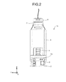
- FIG. 2 is a side view of the workpiece positioning device 15 according to the embodiment.
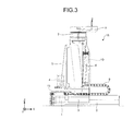
- FIG. 3 is a front view of the workpiece positioning device 15 according to the embodiment.
- the workpiece positioning device 15 includes an X-axis frame 2 and an X-axis movable unit 3.
- the X-axis frame 2 is fixed on a floor.
- the X-axis frame 2 is provided with a ball screw not illustrated (hereinafter, "X-axis ball screw”) and an X-axis guide rail not illustrated (hereinafter, "X-axis guide rail”).
- the X-axis movable unit 3 is attached to a nut of the X-axis ball screw to be guided by the X-axis guide rail in an X-axis direction.
- a connector box 13 is placed at one end of the X-axis frame 2 and below a Z-axis frame 5.
- the connector box 13 includes therein an X-axis motor 1 that acts as a driving source for rotating the X-axis ball screw.
- a rotational motion of the X-axis motor 1 is converted into a linear motion of the X-axis direction by the X-axis ball screw and the X-axis guide rail.
- the X-axis movable unit 3 moves in the X-axis direction.
- the workpiece positioning device 15 includes a first moving unit that includes the X-axis frame 2 and the X-axis movable unit 3 and is movable in a horizontal X-axis direction.
- a Y-axis direction which is a direction perpendicular to the moving direction (X-axis direction) of the X-axis movable unit 3 on a horizontal plane, is the width direction of the X-axis frame 2 and the X-axis movable unit 3.
- the X-axis frame 2 and the X-axis movable unit 3 are formed to have the same width.
- the Z-axis frame 5 is placed on the X-axis movable unit 3. Moreover, the Z-axis frame 5 is formed in such a manner that the width of the Z-axis frame 5 for the X-axis direction that is the traveling direction of the X-axis movable unit 3 is the same as that of the X-axis frame 2 or is smaller than that of the X-axis frame 2. In other words, when a Y-axis direction is a width direction of the Z-axis frame 5, the width of the Z-axis frame 5 is kept within the width of the X-axis frame 2.
- the Z-axis frame 5 is provided with a ball screw not illustrated (hereinafter, "Z-axis ball screw”) and a guide rail not illustrated (hereinafter, "Z-axis guide rail”).
- Z-axis ball screw ball screw
- Z-axis guide rail guide rail not illustrated
- a Z-axis movable unit 6 is attached to a nut of the Z-axis ball screw to be guided by the Z-axis guide rail in a Z-axis direction.
- the Z-axis movable unit 6 is attached to the foreside of the Z-axis frame 5.
- a Z-axis motor 4 that acts as a driving source for rotating the Z-axis ball screw is placed at the backside of the Z-axis frame 5.
- the workpiece positioning device 15 further includes a second moving unit that includes the Z-axis frame 5 and the Z-axis movable unit 6 and is movable in a vertical Z-axis direction.
- a hollow actuator 7 as disclosed in International Publication Pamphlet No. WO2009/034817 is placed on an upper end of the Z-axis movable unit 6 as a rotating unit.
- An output shaft of the hollow actuator 7 is a rotation axis parallel to the Z-axis.
- the diameter of the hollow actuator 7 is the same as or smaller than the width-direction length of the X-axis frame 2, in which the width direction is a direction against the traveling direction of the X-axis movable unit 3 when the traveling direction is the X-axis direction.
- a flange 8 is attached to the output shaft of the hollow actuator 7. Along with a rotation of the output shaft of the hollow actuator 7, the flange 8 revolves around an axis parallel to Z-axis.
- the original point of the hollow actuator 7 is a position at which the longitudinal direction axis line of the flange 8 and the traveling direction axis line of the X-axis movable unit 3 have the same direction, in which the traveling direction of the X-axis movable unit 3 is the X-axis direction.
- the position of the flange 8 becomes an initial state position.
- the width-direction length of the flange 8 is the same as or smaller than the width-direction length of the X-axis frame 2, in which the width direction is a direction against the traveling direction of the X-axis movable unit 3 when the traveling direction is the X-axis direction. In other words, when the width direction of the flange 8 located at the initial state is the Y-axis direction, the width of the flange 8 is kept within the width of the X-axis frame 2.
- the longitudinal length of the flange 8 is one-half of the movable range of Y-axis.
- One end of the flange 8 is fixed to the output shaft of the hollow actuator 7 and the other end has an opening to which a jig that includes a contact sensor, a proximity switch, and the like is attached.
- a cable of the X-axis motor 1, a cable of the Z-axis motor 4, and a cable of the hollow actuator 7, witch drive the shafts from a control panel not illustrated, are attached to the connector box 13.
- the cable of the X-axis motor 1 is directly connected to a connector area of the X-axis motor 1.
- the cable of the Z-axis motor 4 is connected to a connector area of the Z-axis motor 4 via an X-axis cableveyor 9 attached to the top of the X-axis frame 2.
- the cable of the hollow actuator 7 is connected to a connector area of the hollow actuator 7 via the X-axis cableveyor 9 similarly to the cable of the Z-axis motor 4 and then a Z-axis cableveyor 10 fixed to the Z-axis frame 5.
- a cable for activating the jig attached to the flange 8 passes through a hollow part of the hollow actuator 7.
- a horizontal operation is performed by causing the X-axis ball screw engaged with the X-axis motor 1 by an X-axis coupling to slide the X-axis movable unit 3 in the X-axis direction when the X-axis motor 1 is driven.
- the horizontal operation is performed when X-axis direction positioning is performed.
- a raising and lowering operation is performed by causing the Z-axis ball screw to raise and lower the Z-axis movable unit 6 by using a belt by which a pulley of the Z-axis motor 4 is engaged with a pulley of the Z-axis ball screw when the Z-axis motor 4 is driven.
- the raising and lowering operation is performed when Z-axis direction positioning is performed.
- a rotation operation is performed by making the hollow actuator 7 rotate the flange 8 attached to its top in order to enable the Y-axis direction movement.
- the rotation operation is performed when Y-axis direction positioning is performed.
- the workpiece positioning device 15 described above has a configuration that the device size is not larger than the width of the X-axis frame 2 and the Y-axis direction movement is realized by a rotation operation. Therefore, a footprint can be reduced.
- the workpiece positioning device 15 has a configuration that the width of the second moving unit including the Z-axis frame 5 and the Z-axis movable unit 6 and the width of the hollow actuator 7 are kept within the width of the first moving unit that includes the X-axis frame 2 and the X-axis movable unit 3, a footprint can be reduced.
- the workpiece positioning device 15 has a configuration that the width of the Z-axis frame 5 and the width of the hollow actuator 7 are kept within the width of the X-axis movable unit 3 when the width of the X-axis frame 2 is smaller than that of the X-axis movable unit 3, a footprint can be reduced.
- the workpiece positioning device can be realized by a configuration that the hollow actuator is placed on the X-axis frame, the Z-axis frame is placed on the hollow actuator, and the flange is attached to the distal end of the Z-axis frame.
- each of the X-axis movable unit 3 and the Z-axis movable unit 6 includes a motor and a ball screw.
- the X-axis movable unit 3 and the Z-axis movable unit 6 can be replaced by, for example, a linear motor.
- FIG. 4 is a plan view of a production system 11 according to the embodiment.
- FIG. 5 is a side view of the production system 11 according to the embodiment. It will be explained about the production system that positions a body of an automobile corresponding to a workpiece 14 by using a workpiece conveying device 16.
- the production system 11 has a configuration that the workpiece conveying device 16 that conveys the workpiece 14 extends in the X-axis direction and the workpiece positioning devices 15 are arranged at symmetric positions with a central focus on an X-axis direction axis line 12 in such a manner that the longitudinal direction of the X-axis frame 2 of each of the workpiece positioning devices 15 is the same as the conveyance direction of the workpiece 14 and the X-axis direction.
- the present embodiment has a configuration that the six workpiece positioning devices 15 are arranged at symmetric positions with a central focus on the X-axis direction axis line 12 in which the three devices are located at one side of the symmetric positions.
- the workpiece positioning device 15 has a configuration that a workpiece positioning jig 17 is attached to the flange 8. In an initial state, the height of the workpiece positioning jig 17 is lower than that of the workpiece conveying device 16.
- the workpiece positioning device 15 is placed in such a manner that the longitudinal direction of the X-axis frame 2 is the same as the conveyance direction of the workpiece 14 and the X-axis direction.
- the workpiece positioning jig 17 is placed near the workpiece conveying device 16 in a state where the workpiece positioning jig 17 does not contact the workpiece conveying device 16.
- the workpiece positioning devices 15 are arranged at symmetric positions because a symmetric workpiece is used.
- the embodiment is not limited to this.
- the workpiece positioning devices 15 may be appropriately arranged in such a manner that a centroid balance is located at the central portion of a workpiece.
- the number of the workpiece positioning devices 15 located at one side of symmetric sides may be different from the number of the workpiece positioning devices 15 located at the other side.
- the workpiece 14 is mounted on and conveyed by the workpiece conveying device 16.
- the workpiece conveying device 16 is, for example, a conveyer or a movable carriage.
- the hollow actuator 7 rotates at a predetermined angle and thus the workpiece positioning jig 17 is placed below the workpiece 14.
- the X-axis movable unit 3 drives to operate horizontally and thus the workpiece positioning jig 17 is placed below the attachment position of the workpiece 14.
- the Z-axis movable unit 6 drives to operate vertically and thus the workpiece positioning jig 17 is mounted at the attachment position of the workpiece 14.
- Each of the workpiece positioning devices 15 drives the X-axis movable unit 3, the Z-axis movable unit 6, and the hollow actuator 7 to the set positions in accordance with commands of a controller not illustrated if desired, in order to adjust and determine the position of the workpiece 14.
- the six workpiece positioning devices 15 employed in the present embodiment sequentially perform a series of operations for mounting the workpiece positioning jigs 17 on the workpiece 14 but synchronously perform the operations of the Z-axis movable units 6 for mounting the workpiece positioning jigs 17 on the workpiece 14. Therefore, the workpiece positioning jigs 17 are activated to be substantially simultaneously mounted on the workpiece 14. As a result, the workpiece 14 is positioned by the workpiece positioning devices 15.
- the workpiece positioning devices 15 can appropriately position the workpiece in such a manner that a centroid balance is located at the central portion of the workpiece by performing operations as described above even when a workpiece has an asymmetric shape or has a space in its edge.
- the workpiece 14 is processed by a robot such as a welding robot or a sealing robot that is placed at the periphery of the workpiece.
- a robot such as a welding robot or a sealing robot that is placed at the periphery of the workpiece.
- the workpiece positioning devices 15 are detached from the workpiece 14 and are transferred by the workpiece conveying device 16 to the following process.
- the production system has the configuration that the workpiece positioning devices 15 are arranged to position a workpiece, the production system can reduce a footprint. Moreover, because the workpiece positioning device 15 according to the embodiment performs a movement in a direction (Y-axis direction) perpendicular to the conveyance direction of the workpiece 14 on a horizontal plane by using a rolling mechanism, the production system can be constituted by the same type workpiece positioning devices. On the other hand, when orthogonal three-axis workpiece positioning devices are employed as before, two-type units having different configurations are prepared to arrange the devices at facing positions against the traveling direction of a workpiece.
Landscapes
- Engineering & Computer Science (AREA)
- Mechanical Engineering (AREA)
- Manufacturing & Machinery (AREA)
- Chemical & Material Sciences (AREA)
- Combustion & Propulsion (AREA)
- Transportation (AREA)
- Automatic Assembly (AREA)
- Manipulator (AREA)
Applications Claiming Priority (1)
| Application Number | Priority Date | Filing Date | Title |
|---|---|---|---|
| JP2010275312A JP5170225B2 (ja) | 2010-12-10 | 2010-12-10 | ワーク位置決め装置およびそれを用いた生産システム |
Publications (3)
| Publication Number | Publication Date |
|---|---|
| EP2463183A2 true EP2463183A2 (fr) | 2012-06-13 |
| EP2463183A3 EP2463183A3 (fr) | 2012-07-11 |
| EP2463183B1 EP2463183B1 (fr) | 2015-04-08 |
Family
ID=45349366
Family Applications (1)
| Application Number | Title | Priority Date | Filing Date |
|---|---|---|---|
| EP11192500.4A Not-in-force EP2463183B1 (fr) | 2010-12-10 | 2011-12-08 | Dispositif de positionnement de pièce et système de production l'utilisant |
Country Status (5)
| Country | Link |
|---|---|
| US (1) | US8991037B2 (fr) |
| EP (1) | EP2463183B1 (fr) |
| JP (1) | JP5170225B2 (fr) |
| KR (1) | KR20120065250A (fr) |
| CN (1) | CN102554911A (fr) |
Families Citing this family (3)
| Publication number | Priority date | Publication date | Assignee | Title |
|---|---|---|---|---|
| CN103170784B (zh) * | 2013-03-07 | 2015-11-04 | 广州明珞汽车装备有限公司 | 一种白车身智能定位系统 |
| CN107052751A (zh) * | 2017-04-27 | 2017-08-18 | 嘉善金亿精密铸件有限公司 | 一种工件铆压装置 |
| CN117769513A (zh) * | 2021-08-05 | 2024-03-26 | 日产自动车株式会社 | 模块的安装方法 |
Citations (2)
| Publication number | Priority date | Publication date | Assignee | Title |
|---|---|---|---|---|
| JP2002263965A (ja) | 2001-03-12 | 2002-09-17 | Nissan Motor Co Ltd | 車体搬送装置 |
| WO2009034817A1 (fr) | 2007-09-11 | 2009-03-19 | Kabushiki Kaisha Yaskawa Denki | Actionneur creux |
Family Cites Families (13)
| Publication number | Priority date | Publication date | Assignee | Title |
|---|---|---|---|---|
| JPH0659856B2 (ja) * | 1985-11-14 | 1994-08-10 | 関東自動車工業株式会社 | 部品取り付け治具 |
| JPH0413529A (ja) * | 1990-04-27 | 1992-01-17 | Hitachi Ltd | 加工又は組立装置 |
| JP3249717B2 (ja) * | 1995-06-22 | 2002-01-21 | キヤノン株式会社 | 汎用位置決めクランプ装置 |
| JP3663984B2 (ja) | 1999-08-06 | 2005-06-22 | 日産自動車株式会社 | 車体組立方法および車体組立装置 |
| FR2804929B1 (fr) * | 2000-02-11 | 2002-05-31 | Genus Technologies | Dispositif de centrage et de serrage, notamment de pieces pour carrosserie automobile |
| JP4039114B2 (ja) | 2001-09-26 | 2008-01-30 | 日産自動車株式会社 | 自動車の車体組立方法および車体組立装置 |
| JP4270041B2 (ja) * | 2004-06-24 | 2009-05-27 | 株式会社安川電機 | ロボットの手首装置とこれを備えたロボット |
| DE202004017881U1 (de) | 2004-11-17 | 2006-03-23 | Kuka Schweissanlagen Gmbh | Handlingvorrichtung |
| US7429035B2 (en) * | 2005-09-29 | 2008-09-30 | Wprwmdm, L.L.C. | Equipment handling apparatus |
| US20080000068A1 (en) | 2006-06-28 | 2008-01-03 | Savoy Mark A | Adjustment of work pallets for vehicle body assembly lines |
| WO2008002749A2 (fr) * | 2006-06-28 | 2008-01-03 | Utica Enterprises, Inc. | Positionnement d'une caisse de véhicule sur une chaîne de montage |
| US8066259B2 (en) * | 2006-10-04 | 2011-11-29 | Larin Corporation | Hydraulic jack with lowering control means |
| JP5239402B2 (ja) * | 2008-03-03 | 2013-07-17 | 日産自動車株式会社 | 位置決めテーブル、位置決めクランプ装置、及びメインボディ用位置決め装置。 |
-
2010
- 2010-12-10 JP JP2010275312A patent/JP5170225B2/ja active Active
-
2011
- 2011-11-22 US US13/301,790 patent/US8991037B2/en active Active
- 2011-12-07 CN CN2011104041488A patent/CN102554911A/zh active Pending
- 2011-12-08 EP EP11192500.4A patent/EP2463183B1/fr not_active Not-in-force
- 2011-12-08 KR KR1020110131001A patent/KR20120065250A/ko not_active Ceased
Patent Citations (2)
| Publication number | Priority date | Publication date | Assignee | Title |
|---|---|---|---|---|
| JP2002263965A (ja) | 2001-03-12 | 2002-09-17 | Nissan Motor Co Ltd | 車体搬送装置 |
| WO2009034817A1 (fr) | 2007-09-11 | 2009-03-19 | Kabushiki Kaisha Yaskawa Denki | Actionneur creux |
Also Published As
| Publication number | Publication date |
|---|---|
| CN102554911A (zh) | 2012-07-11 |
| KR20120065250A (ko) | 2012-06-20 |
| US20120148377A1 (en) | 2012-06-14 |
| EP2463183B1 (fr) | 2015-04-08 |
| EP2463183A3 (fr) | 2012-07-11 |
| JP2012121111A (ja) | 2012-06-28 |
| JP5170225B2 (ja) | 2013-03-27 |
| US8991037B2 (en) | 2015-03-31 |
Similar Documents
| Publication | Publication Date | Title |
|---|---|---|
| CN109079044B (zh) | 压力机的工件输送装置 | |
| EP3238885B1 (fr) | Robot à deux bras | |
| EP2783807A2 (fr) | Système de robot, procédé d'étalonnage et procédé de production d'une pièce à traiter | |
| KR101558676B1 (ko) | 리스폿 지그 | |
| US10252413B2 (en) | Robot and robot system | |
| CN106863266B (zh) | 机器人、控制装置以及机器人系统 | |
| CN106002931B (zh) | 机器人系统 | |
| KR101472266B1 (ko) | 다축 그리퍼 장치 | |
| EP2401118B1 (fr) | Dispositif d'outillage destiné à un manipulateur | |
| US11247329B2 (en) | Work device and dual-arm work device | |
| US10549433B2 (en) | Robot device | |
| US10857674B2 (en) | Robot system and robot | |
| KR101095690B1 (ko) | 3축 로봇 및 이를 이용한 갠트리형 공작 시스템 | |
| CN107053252B (zh) | 机器人 | |
| US20160288341A1 (en) | Robot system | |
| US20160318179A1 (en) | Robot system | |
| CN106002932A (zh) | 机器人系统 | |
| US10814440B1 (en) | Method of assembling an automated modular tool | |
| CN103149880A (zh) | 加工装置 | |
| TW201617192A (zh) | 機器人及機器人系統 | |
| EP0500309A2 (fr) | Dispositif de fixation pour les pièces | |
| EP2463183B1 (fr) | Dispositif de positionnement de pièce et système de production l'utilisant | |
| JP2019520224A5 (fr) | ||
| CN108393866B (zh) | 机器人系统 | |
| JP2019520224A (ja) | 組立装置および組立装置の制御方法 |
Legal Events
| Date | Code | Title | Description |
|---|---|---|---|
| PUAL | Search report despatched |
Free format text: ORIGINAL CODE: 0009013 |
|
| PUAI | Public reference made under article 153(3) epc to a published international application that has entered the european phase |
Free format text: ORIGINAL CODE: 0009012 |
|
| AK | Designated contracting states |
Kind code of ref document: A2 Designated state(s): AL AT BE BG CH CY CZ DE DK EE ES FI FR GB GR HR HU IE IS IT LI LT LU LV MC MK MT NL NO PL PT RO RS SE SI SK SM TR |
|
| AX | Request for extension of the european patent |
Extension state: BA ME |
|
| AK | Designated contracting states |
Kind code of ref document: A3 Designated state(s): AL AT BE BG CH CY CZ DE DK EE ES FI FR GB GR HR HU IE IS IT LI LT LU LV MC MK MT NL NO PL PT RO RS SE SI SK SM TR |
|
| AX | Request for extension of the european patent |
Extension state: BA ME |
|
| RIC1 | Information provided on ipc code assigned before grant |
Ipc: B62D 65/18 20060101AFI20120607BHEP |
|
| 17P | Request for examination filed |
Effective date: 20121122 |
|
| GRAP | Despatch of communication of intention to grant a patent |
Free format text: ORIGINAL CODE: EPIDOSNIGR1 |
|
| INTG | Intention to grant announced |
Effective date: 20141103 |
|
| GRAS | Grant fee paid |
Free format text: ORIGINAL CODE: EPIDOSNIGR3 |
|
| GRAA | (expected) grant |
Free format text: ORIGINAL CODE: 0009210 |
|
| AK | Designated contracting states |
Kind code of ref document: B1 Designated state(s): AL AT BE BG CH CY CZ DE DK EE ES FI FR GB GR HR HU IE IS IT LI LT LU LV MC MK MT NL NO PL PT RO RS SE SI SK SM TR |
|
| REG | Reference to a national code |
Ref country code: GB Ref legal event code: FG4D |
|
| REG | Reference to a national code |
Ref country code: CH Ref legal event code: EP |
|
| REG | Reference to a national code |
Ref country code: IE Ref legal event code: FG4D |
|
| REG | Reference to a national code |
Ref country code: AT Ref legal event code: REF Ref document number: 720331 Country of ref document: AT Kind code of ref document: T Effective date: 20150515 |
|
| REG | Reference to a national code |
Ref country code: DE Ref legal event code: R096 Ref document number: 602011015402 Country of ref document: DE Effective date: 20150521 |
|
| REG | Reference to a national code |
Ref country code: AT Ref legal event code: MK05 Ref document number: 720331 Country of ref document: AT Kind code of ref document: T Effective date: 20150408 |
|
| REG | Reference to a national code |
Ref country code: NL Ref legal event code: VDEP Effective date: 20150408 |
|
| REG | Reference to a national code |
Ref country code: LT Ref legal event code: MG4D |
|
| PG25 | Lapsed in a contracting state [announced via postgrant information from national office to epo] |
Ref country code: NL Free format text: LAPSE BECAUSE OF FAILURE TO SUBMIT A TRANSLATION OF THE DESCRIPTION OR TO PAY THE FEE WITHIN THE PRESCRIBED TIME-LIMIT Effective date: 20150408 |
|
| PG25 | Lapsed in a contracting state [announced via postgrant information from national office to epo] |
Ref country code: LT Free format text: LAPSE BECAUSE OF FAILURE TO SUBMIT A TRANSLATION OF THE DESCRIPTION OR TO PAY THE FEE WITHIN THE PRESCRIBED TIME-LIMIT Effective date: 20150408 Ref country code: HR Free format text: LAPSE BECAUSE OF FAILURE TO SUBMIT A TRANSLATION OF THE DESCRIPTION OR TO PAY THE FEE WITHIN THE PRESCRIBED TIME-LIMIT Effective date: 20150408 Ref country code: ES Free format text: LAPSE BECAUSE OF FAILURE TO SUBMIT A TRANSLATION OF THE DESCRIPTION OR TO PAY THE FEE WITHIN THE PRESCRIBED TIME-LIMIT Effective date: 20150408 Ref country code: PT Free format text: LAPSE BECAUSE OF FAILURE TO SUBMIT A TRANSLATION OF THE DESCRIPTION OR TO PAY THE FEE WITHIN THE PRESCRIBED TIME-LIMIT Effective date: 20150810 Ref country code: FI Free format text: LAPSE BECAUSE OF FAILURE TO SUBMIT A TRANSLATION OF THE DESCRIPTION OR TO PAY THE FEE WITHIN THE PRESCRIBED TIME-LIMIT Effective date: 20150408 Ref country code: NO Free format text: LAPSE BECAUSE OF FAILURE TO SUBMIT A TRANSLATION OF THE DESCRIPTION OR TO PAY THE FEE WITHIN THE PRESCRIBED TIME-LIMIT Effective date: 20150708 |
|
| PG25 | Lapsed in a contracting state [announced via postgrant information from national office to epo] |
Ref country code: GR Free format text: LAPSE BECAUSE OF FAILURE TO SUBMIT A TRANSLATION OF THE DESCRIPTION OR TO PAY THE FEE WITHIN THE PRESCRIBED TIME-LIMIT Effective date: 20150709 Ref country code: LV Free format text: LAPSE BECAUSE OF FAILURE TO SUBMIT A TRANSLATION OF THE DESCRIPTION OR TO PAY THE FEE WITHIN THE PRESCRIBED TIME-LIMIT Effective date: 20150408 Ref country code: RS Free format text: LAPSE BECAUSE OF FAILURE TO SUBMIT A TRANSLATION OF THE DESCRIPTION OR TO PAY THE FEE WITHIN THE PRESCRIBED TIME-LIMIT Effective date: 20150408 Ref country code: AT Free format text: LAPSE BECAUSE OF FAILURE TO SUBMIT A TRANSLATION OF THE DESCRIPTION OR TO PAY THE FEE WITHIN THE PRESCRIBED TIME-LIMIT Effective date: 20150408 Ref country code: IS Free format text: LAPSE BECAUSE OF FAILURE TO SUBMIT A TRANSLATION OF THE DESCRIPTION OR TO PAY THE FEE WITHIN THE PRESCRIBED TIME-LIMIT Effective date: 20150808 |
|
| REG | Reference to a national code |
Ref country code: DE Ref legal event code: R097 Ref document number: 602011015402 Country of ref document: DE |
|
| PG25 | Lapsed in a contracting state [announced via postgrant information from national office to epo] |
Ref country code: DK Free format text: LAPSE BECAUSE OF FAILURE TO SUBMIT A TRANSLATION OF THE DESCRIPTION OR TO PAY THE FEE WITHIN THE PRESCRIBED TIME-LIMIT Effective date: 20150408 Ref country code: EE Free format text: LAPSE BECAUSE OF FAILURE TO SUBMIT A TRANSLATION OF THE DESCRIPTION OR TO PAY THE FEE WITHIN THE PRESCRIBED TIME-LIMIT Effective date: 20150408 |
|
| PLBE | No opposition filed within time limit |
Free format text: ORIGINAL CODE: 0009261 |
|
| STAA | Information on the status of an ep patent application or granted ep patent |
Free format text: STATUS: NO OPPOSITION FILED WITHIN TIME LIMIT |
|
| PG25 | Lapsed in a contracting state [announced via postgrant information from national office to epo] |
Ref country code: PL Free format text: LAPSE BECAUSE OF FAILURE TO SUBMIT A TRANSLATION OF THE DESCRIPTION OR TO PAY THE FEE WITHIN THE PRESCRIBED TIME-LIMIT Effective date: 20150408 Ref country code: CZ Free format text: LAPSE BECAUSE OF FAILURE TO SUBMIT A TRANSLATION OF THE DESCRIPTION OR TO PAY THE FEE WITHIN THE PRESCRIBED TIME-LIMIT Effective date: 20150408 Ref country code: RO Free format text: LAPSE BECAUSE OF NON-PAYMENT OF DUE FEES Effective date: 20150408 Ref country code: SK Free format text: LAPSE BECAUSE OF FAILURE TO SUBMIT A TRANSLATION OF THE DESCRIPTION OR TO PAY THE FEE WITHIN THE PRESCRIBED TIME-LIMIT Effective date: 20150408 |
|
| 26N | No opposition filed |
Effective date: 20160111 |
|
| PG25 | Lapsed in a contracting state [announced via postgrant information from national office to epo] |
Ref country code: IT Free format text: LAPSE BECAUSE OF FAILURE TO SUBMIT A TRANSLATION OF THE DESCRIPTION OR TO PAY THE FEE WITHIN THE PRESCRIBED TIME-LIMIT Effective date: 20150408 |
|
| PGFP | Annual fee paid to national office [announced via postgrant information from national office to epo] |
Ref country code: DE Payment date: 20151223 Year of fee payment: 5 |
|
| PG25 | Lapsed in a contracting state [announced via postgrant information from national office to epo] |
Ref country code: BE Free format text: LAPSE BECAUSE OF NON-PAYMENT OF DUE FEES Effective date: 20151231 Ref country code: SI Free format text: LAPSE BECAUSE OF FAILURE TO SUBMIT A TRANSLATION OF THE DESCRIPTION OR TO PAY THE FEE WITHIN THE PRESCRIBED TIME-LIMIT Effective date: 20150408 |
|
| PG25 | Lapsed in a contracting state [announced via postgrant information from national office to epo] |
Ref country code: MC Free format text: LAPSE BECAUSE OF FAILURE TO SUBMIT A TRANSLATION OF THE DESCRIPTION OR TO PAY THE FEE WITHIN THE PRESCRIBED TIME-LIMIT Effective date: 20150408 Ref country code: LU Free format text: LAPSE BECAUSE OF FAILURE TO SUBMIT A TRANSLATION OF THE DESCRIPTION OR TO PAY THE FEE WITHIN THE PRESCRIBED TIME-LIMIT Effective date: 20151208 |
|
| REG | Reference to a national code |
Ref country code: CH Ref legal event code: PL |
|
| GBPC | Gb: european patent ceased through non-payment of renewal fee |
Effective date: 20151208 |
|
| PG25 | Lapsed in a contracting state [announced via postgrant information from national office to epo] |
Ref country code: BE Free format text: LAPSE BECAUSE OF FAILURE TO SUBMIT A TRANSLATION OF THE DESCRIPTION OR TO PAY THE FEE WITHIN THE PRESCRIBED TIME-LIMIT Effective date: 20150408 |
|
| REG | Reference to a national code |
Ref country code: IE Ref legal event code: MM4A |
|
| REG | Reference to a national code |
Ref country code: FR Ref legal event code: ST Effective date: 20160831 |
|
| PG25 | Lapsed in a contracting state [announced via postgrant information from national office to epo] |
Ref country code: CH Free format text: LAPSE BECAUSE OF NON-PAYMENT OF DUE FEES Effective date: 20151231 Ref country code: LI Free format text: LAPSE BECAUSE OF NON-PAYMENT OF DUE FEES Effective date: 20151231 Ref country code: GB Free format text: LAPSE BECAUSE OF NON-PAYMENT OF DUE FEES Effective date: 20151208 Ref country code: IE Free format text: LAPSE BECAUSE OF NON-PAYMENT OF DUE FEES Effective date: 20151208 |
|
| PG25 | Lapsed in a contracting state [announced via postgrant information from national office to epo] |
Ref country code: FR Free format text: LAPSE BECAUSE OF NON-PAYMENT OF DUE FEES Effective date: 20151231 |
|
| PG25 | Lapsed in a contracting state [announced via postgrant information from national office to epo] |
Ref country code: SM Free format text: LAPSE BECAUSE OF FAILURE TO SUBMIT A TRANSLATION OF THE DESCRIPTION OR TO PAY THE FEE WITHIN THE PRESCRIBED TIME-LIMIT Effective date: 20150408 Ref country code: HU Free format text: LAPSE BECAUSE OF FAILURE TO SUBMIT A TRANSLATION OF THE DESCRIPTION OR TO PAY THE FEE WITHIN THE PRESCRIBED TIME-LIMIT; INVALID AB INITIO Effective date: 20111208 Ref country code: BG Free format text: LAPSE BECAUSE OF FAILURE TO SUBMIT A TRANSLATION OF THE DESCRIPTION OR TO PAY THE FEE WITHIN THE PRESCRIBED TIME-LIMIT Effective date: 20150408 |
|
| PG25 | Lapsed in a contracting state [announced via postgrant information from national office to epo] |
Ref country code: SE Free format text: LAPSE BECAUSE OF FAILURE TO SUBMIT A TRANSLATION OF THE DESCRIPTION OR TO PAY THE FEE WITHIN THE PRESCRIBED TIME-LIMIT Effective date: 20150408 Ref country code: CY Free format text: LAPSE BECAUSE OF FAILURE TO SUBMIT A TRANSLATION OF THE DESCRIPTION OR TO PAY THE FEE WITHIN THE PRESCRIBED TIME-LIMIT Effective date: 20150408 |
|
| REG | Reference to a national code |
Ref country code: DE Ref legal event code: R119 Ref document number: 602011015402 Country of ref document: DE |
|
| PG25 | Lapsed in a contracting state [announced via postgrant information from national office to epo] |
Ref country code: TR Free format text: LAPSE BECAUSE OF FAILURE TO SUBMIT A TRANSLATION OF THE DESCRIPTION OR TO PAY THE FEE WITHIN THE PRESCRIBED TIME-LIMIT Effective date: 20150408 Ref country code: MT Free format text: LAPSE BECAUSE OF FAILURE TO SUBMIT A TRANSLATION OF THE DESCRIPTION OR TO PAY THE FEE WITHIN THE PRESCRIBED TIME-LIMIT Effective date: 20150408 |
|
| PG25 | Lapsed in a contracting state [announced via postgrant information from national office to epo] |
Ref country code: DE Free format text: LAPSE BECAUSE OF NON-PAYMENT OF DUE FEES Effective date: 20170701 |
|
| PG25 | Lapsed in a contracting state [announced via postgrant information from national office to epo] |
Ref country code: MK Free format text: LAPSE BECAUSE OF FAILURE TO SUBMIT A TRANSLATION OF THE DESCRIPTION OR TO PAY THE FEE WITHIN THE PRESCRIBED TIME-LIMIT Effective date: 20150408 |
|
| PG25 | Lapsed in a contracting state [announced via postgrant information from national office to epo] |
Ref country code: AL Free format text: LAPSE BECAUSE OF FAILURE TO SUBMIT A TRANSLATION OF THE DESCRIPTION OR TO PAY THE FEE WITHIN THE PRESCRIBED TIME-LIMIT Effective date: 20150408 |