EP2463429A2 - Appareil de couture de boucle de ceinture et procédé de commande correspondant - Google Patents
Appareil de couture de boucle de ceinture et procédé de commande correspondant Download PDFInfo
- Publication number
- EP2463429A2 EP2463429A2 EP20110192509 EP11192509A EP2463429A2 EP 2463429 A2 EP2463429 A2 EP 2463429A2 EP 20110192509 EP20110192509 EP 20110192509 EP 11192509 A EP11192509 A EP 11192509A EP 2463429 A2 EP2463429 A2 EP 2463429A2
- Authority
- EP
- European Patent Office
- Prior art keywords
- belt loop
- loop
- clamp
- belt
- longitudinal direction
- Prior art date
- Legal status (The legal status is an assumption and is not a legal conclusion. Google has not performed a legal analysis and makes no representation as to the accuracy of the status listed.)
- Granted
Links
Images




Classifications
-
- D—TEXTILES; PAPER
- D05—SEWING; EMBROIDERING; TUFTING
- D05B—SEWING
- D05B35/00—Work-feeding or -handling elements not otherwise provided for
- D05B35/06—Work-feeding or -handling elements not otherwise provided for for attaching bands, ribbons, strips, or tapes or for binding
- D05B35/066—Work-feeding or -handling elements not otherwise provided for for attaching bands, ribbons, strips, or tapes or for binding for attaching small textile pieces, e.g. labels, belt loops
- D05B35/068—Work-feeding or -handling elements not otherwise provided for for attaching bands, ribbons, strips, or tapes or for binding for attaching small textile pieces, e.g. labels, belt loops for attaching belt loops
-
- D—TEXTILES; PAPER
- D05—SEWING; EMBROIDERING; TUFTING
- D05B—SEWING
- D05B35/00—Work-feeding or -handling elements not otherwise provided for
- D05B35/06—Work-feeding or -handling elements not otherwise provided for for attaching bands, ribbons, strips, or tapes or for binding
- D05B35/066—Work-feeding or -handling elements not otherwise provided for for attaching bands, ribbons, strips, or tapes or for binding for attaching small textile pieces, e.g. labels, belt loops
Definitions
- the present invention relates to a belt loop sewing apparatus for feeding, to a sewing machine, a belt loop for inserting a belt therethrough which is to be sewn onto a waist part of pants or skirts, and a method of controlling the belt loop sewing apparatus.
- JP-A-2000-167282 in some cases in which a belt loop is formed by a raw material which is hard to fold back in a desirable direction, for example, a raw material having an oblique texture and such a characteristic as to be bent obliquely along the texture, an end of the belt loop is protruded beyond a guide member, resulting in an occurrence of a dog ear even if a portion to be folded back in the belt loop is regulated by the guide member.
- a first aspect of the invention is directed to a belt loop sewing apparatus including: a holding unit configured to hold one of ends in a longitudinal direction of a belt loop disposed in the longitudinal direction; a clamp unit including a loop clamp capable of clamping or releasing the other end of the belt loop from a holding position set by the holding unit, the clamp unit configured to move the loop clamp in a direction crossing the longitudinal direction; a fork unit including, on a tip thereof, a fork formed into a forked shape and interposing the belt loop provided between the holding unit and the loop clamp, the fork unit configured to be rotatable around an axis in the direction crossing the longitudinal direction and movable in the direction crossing the longitudinal direction together with the loop clamp to fold one of the ends of the belt loop back toward a central side of the belt loop by a rotation of the fork unit; and a controller configured to control the rotation of the fork unit to fold the one of the ends of the belt loop back toward the central side of the belt loop, wherein the held belt loop is moved in the direction crossing the
- the "predetermined amount” represents a value having a size and an orientation together and determines a moving amount for the movement of the loop clamp, and may include a moving direction thereof (a positive direction or a negative direction).
- a second aspect of the invention has the same structure as the structure according to the first aspect, and the controller may be configured to move the loop clamp holding the belt loop by the predetermined amount in the direction crossing the longitudinal direction and then to rotate the fork unit to fold the other end of the belt loop back toward the central side of the belt loop in a state in which the one end side of the belt loop is sewn onto a cloth by the sewing machine and the other end side of the belt loop is clamped by the loop clamp.
- a third aspect of the invention has the same structure as the structure according to the first or second aspect, and the sewing machine may further includes: an operating unit configured to previously set and input a direction crossing the longitudinal direction and a moving amount in the direction.
- a fourth aspect of the invention has the same structure as the structure according to the first aspect, and the controller may be configured to set a moving direction of the loop clamp to be the direction crossing the longitudinal direction and a direction in which one of the ends of the belt loop is protruded from the belt loop when the one of the ends is folded back.
- a fifth aspect of the invention has the same structure as the structure according to the second aspect, and the controller may be configured to set a moving direction of the loop clamp to be the direction crossing the longitudinal direction and a reverse direction to a direction in which the other end of the belt loop is protruded from the belt loop when the other end is folded back.
- the loop clamp interposing the belt loop is moved by the predetermined amount in a reverse direction to the direction in which the other end is protruded, thereby regulating the orientation of the belt loop and then folding back the other end of the belt loop by means of the fork unit.
- the direction crossing the longitudinal direction and the moving amount in the direction can be previously set and input. Therefore, it is possible to continuously carry out an operation from a serial fold-back work to a work for sewing the belt loop.
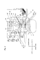
- a belt loop sewing apparatus 10 includes a belt loop sewing machine 1 having a sewing machine body 2 and a belt loop feeding apparatus 100.
- the belt loop feeding apparatus 100 constituting a main part of the present invention includes holding unit (a loop holding pawl 66, a loop pull-in portion 60b) for holding one of ends in a longitudinal direction of a belt loop B disposed in the longitudinal direction, a clamp unit 30 which has a loop clamp 31 capable of interposing or releasing the other end side of the belt loop B from a holding position ser by the holding unit and enables a movement of the loop clamp 31 in a direction crossing the longitudinal direction, a fork unit 38 which has, on a tip, a fork portion 38A forked to interpose the belt loop B between the holding unit and the loop clamp 31, is rotatable around an axis in the direction crossing the longitudinal direction and folds one of the ends of the belt loop B back toward a central side of the belt loop through a rotation and holds the end, and controller for controlling the rotation of the fork unit 38 in order to fold one of the ends of the belt loop B back toward the central side of the belt loop B, and feeds the belt loop held by the
- the sewing machine body 2 constituting the belt loop sewing machine has a frame structure including a bed portion 2a, a cylinder bed portion 2d extended horizontally from the bed portion 2a, a vertical drum portion 2b erected from the bed portion 2a, and an arm portion 2c extended from the vertical drum portion 2b along a part above the bed portion 2a and the cylinder bed portion 2d.
- a horizontal direction along a longitudinal direction of the cylinder bed portion 2d and the arm portion 2c is set to be a Y-axis direction
- a horizontal direction which is orthogonal to the Y-axis direction is set to be an X-axis direction
- a vertical direction is set to be a Z-axis direction
- a surface portion side of the arm portion 2c to be one end side in the Y-axis direction is referred to as a "front side”
- the vertical drum portion 2b side to be the other end side in the Y-axis direction is referred to as an "deeper side" if necessary for explanation.
- a loop feeding mechanism 60 is positioned on a side of the belt loop sewing machine 1 and is disposed on a table T.
- the loop feeding mechanism 60 includes a loop send-out portion 60a fixed to a front side of the clamp unit 30 and a loop pull-in portion 60b fixed to a deeper side through the clamp unit 30.
- the loop send-out portion 60a includes a delivering roller 61 ( Fig. 3 ) for holding a long tape material wound around a reel and delivering the tape material to a send-out port provided on the deeper side, a send-out motor 62 ( Fig. 3 ) for rotating and driving the delivering roller 61, a cutter 63 ( Fig. 3 ) for cutting the tape material sent out in a predetermined length, and an air cylinder 64 for cutting ( Fig. 3 ) which drives the cutter 63.
- the loop pull-in portion 60b constitutes holding unit for holding one of the ends in the longitudinal direction of the belt loop.
- the loop pull-in portion 60b includes a loop holding pawl 66 serving as a loop holding portion for interposing and holding a tip of the tape material sent out of the send-out port from upper and lower sides, a rod 65 having the loop holding pawl 66 on a tip, a Y-axis motor 68 ( Fig. 3 ) for moving the rod 65 forward and backward in the Y-axis direction, and an air cylinder 67 ( Fig. 3 ) for switching interposing and releasing states of the looping holding pawl 66.
- the loop holding pawl 66 can be moved forward and backward between the send-out port of the loop send-out portion 60a and a standby position on the loop pull-in portion 60b side (the deeper side) beyond the clamp unit 30 with the forward and backward movements of the rod 65.
- the tape material T is disposed to pass through the loop clamp 31 of the clamp unit 30 when the loop holding pawl 66 holding the tip of the tape material T is moved from the send-out port to the standby position.
- the cutter 63 is disposed opposite to a tape material moving path between the reel portion and the send-out port and cuts the tape material in an operation of the air cylinder 64 for cutting.
- a length of the tape material to be cut from the tip to the cutter 63, that is, a length of the belt loop B is determined by controlling a driving amount of the send-out motor 62 and a moving amount of the loop holding pawl 66 through controller 80.
- the clamp unit 30 has a loop clamp capable of interposing or releasing the other end of the belt loop in a state in which the longitudinal direction of the loop is turned into a predetermined direction, and can move the loop clamp in the direction crossing the longitudinal direction.
- the clamp unit 30 is disposed between the loop send-out portion 60a and the loop pull-in portion 60b in the loop feeding mechanism 60 in the Y-axis direction, and is positioned at an opposite side to the belt loop sewing machine 1 with an X-axis direction line passing through the loop send-out portion 60a and the loop pull-in portion 60b interposed therebetween in the X-axis direction.
- the clamp unit 30 includes a hollow support member 34 fixed onto the table T, a holding block 32 supported on the support member 34 movably in the X-axis direction, the Y-axis direction and the Z-axis direction, and the loop clamp 31 supported on a tip of the holding block 32 (left in the X-axis direction in Fig. 1 ) and having an upper clamp 31a and a lower clamp 31b which interpose the belt loop B therebetween as shown in Fig. 4 .
- an air cylinder 33 for a clamp serves to move the upper clamp 31 a of the loop clamp 31 upward and downward to switch the interposing and releasing states of the belt loop B.
- the X-axis motor 35 for a clamp serves to move the holding block 32 in the X-axis direction.
- the Y-axis motor 36 for the clamp serves to move the holding block 32 in the Y-axis direction.
- the Z-axis air cylinder 37 for a clamp serves to move the holding block 32 vertically in the Z-axis direction.
- the lower clamp 31b of the loop clamp 31 is fixed to the holding block 32 and the upper clamp 31a is supported to be vertically movable just above the lower clamp 31b.
- a lower surface of a tip portion of the upper clamp 31a has a concave holding portion 31c formed thereon in a Y direction.
- the holding portion 31c has a slightly greater width than a width of the belt loop B.
- the belt loop B is held to be fitted in the holding portion 31c.
- the belt loop B is fitted and held in the holding portion 31c so that the hold is carried out with a longitudinal direction thereof set along the Y-axis direction.
- a holding pressure of the belt loop B through the air cylinder 33 for a clamp is regulated in such a manner that the belt loop B can be pulled out upon receipt of a certain tension in the Y-axis direction.
- the holding block 32 is supported on the support member 34 in a combination of a slide guide capable of carrying out a sliding motion in each of the X-, Y- and Z-axis directions, for example, and can perform a movement in each of the directions, which is not shown.
- the loop clamp 31 can be moved, together with the holding block 32, to an optional position and an optional height over an X - Y plane in cooperation with the X- and Y-axis motors 35 and 36 for a clamp and the Z-axis cylinder 37 for a clamp.
- the loop clamp 31 by moving the loop clamp 31, it is possible to deliver the belt loop B from a feeding position through the loop feeding mechanism 60 to a sewing executing position in the vicinity of the tip of the cylinder bed portion 2d of the sewing machine shown in Fig. 4 , to move the belt loop B depending on each of sewing places in the case in which a sewing operation is carried out over the places of the belt loop B in the sewing executing position, or to regulate an orientation or arrangement of the belt loop B in such a manner that the belt loop B takes a predetermined shape of the belt loop.
- the forked member 38 is provided adjacently to the loop clamp 31 at the loop pull-out portion 60b side (the deeper side) side by side with the holding block 32, and can be moved in the direction crossing the longitudinal direction together with the loop clamp 31.
- the fork unit 38 is supported on the holding block 32 so as to be rotatable around an X axis and to be forward or backward movable in the X-axis direction with respect to the holding block 32.
- a forward or backward moving operation in the X-axis direction is applied to the fork unit 38 by means of an air cylinder 40 for a fork which is provided on the holding block 32 so that the fork unit 38 is moved to a position placed side by side with the loop clamp 31 in the forward movement and is moved rightward from the loop clamp 31 in the backward movement.
- a rotating operation is applied to the fork unit 38 in a normal direction or a reverse direction around the X axis by means of a rotary actuator 41 provided on the holding block 32.
- the fork unit 38 is provided with the fork portion 38A taking a forked shape in which two bar-shaped members are extended leftward in parallel from a tip portion (a left end in Fig. 1 ) in the X-axis direction, and is disposed in such a manner that the belt loop B is inserted into a part between the two bar-shaped members and is thus positioned when the fork unit 38 is moved forward.
- the fork unit 38 By rotating the fork unit 38 in the normal direction or the reverse direction around the X axis in a state in which the belt loop B is inserted into the part between the fork portions 38A, it is possible to wind the belt loop B by means of the fork portion 38A, thereby folding back the end of the belt loop B.
- the fork unit 38 can be rotated around an axis in the direction crossing the longitudinal direction and can be moved in the direction crossing the longitudinal direction together with the loop clamp 31, and folds back one of the ends of the belt loop toward the central side of the belt loop through a rotation and holds the end in that state.
- the belt loop sewing machine 1 is fixedly disposed on the table T, and includes at least a sewing machine body 2, a needle 11 to which a vertical operation is to be applied by a well-known needle vertical moving mechanism (not shown), a throat plate 3 having a needle hole (not shown) for causing the needle 11 to penetrate formed thereon and fixed onto an upper surface of the cylinder bed 2d, a loop presser mechanism 50 having a bodice feeding lower plate 51 disposed on the throat plate 3 and serving to mount a cloth (a bodice) to which the belt loop B is to be sewn and a loop presser 52 for pressing the belt loop B by a downward moving operation onto the bodice feeding lower plate 51, a cloth presser mechanism 70 having a cloth presser 71 for holding the cloth, and a well-known shuttle mechanism (not shown) provided in the cylinder bed portion 2d.
- the needle 11 and the shuttle mechanism are coupled to a sewing machine motor 13 ( Fig. 3 ) such as a servo motor and are operated interlockingly with a driving source.
- the loop presser mechanism 50 includes a cloth feeding table 59 disposed movably in the X-axis direction and the Y-axis direction over the cylinder bed portion 2d, and the loop presser 52 supported on the tip attaching portion 58 of the cloth feeding table 59 so as to be vertically movable.
- the cloth feeding table 59 is coupled to an X-axis motor 53 for a cloth (an X-axis motor) and a Y-axis motor 54 for a cloth (a Y-axis motor) which are disposed in the cylinder bed portion 2d.
- the X-axis motor 53 moves the cloth feeding table 59 in the X-axis direction and the Y-axis motor 54 moves the cloth feeding table 59 in the Y-axis direction.
- Both the X-axis motor 53 and the Y-axis motor 54 are pulse motors, and a feedback control based on outputs of encoders 55 and 56 provided on respective output shafts is carried out in order to position the belt loop B and the cloth in such a manner that a needle location is carried out into a predetermined stitch point determined in a sewing pattern synchronously with a needle location for each needle.
- the movement in the X direction of the cloth feeding table 59 may cause the loop presser 52 to be moved over an approximation straight line in the X direction by enabling the base portion of the cloth feeding table to be rotated around a vertical axis.
- a vertical moving operation is applied to the loop presser 52 by means of a pulse motor 57 for a loop presser ( Fig. 3 ) which is fixed to the cloth feeding table 59.
- a lower end of the loop presser 52 is provided with an almost rectangular frame portion 52a having a slightly greater width than the width of the belt loop B.
- a support member 72 has a base portion supported on the cloth feeding table 59 movably in the Y direction, and is extended in the Y-axis direction at the side of the cylinder bed portion 2d.
- the support member 72 fixedly supports, on a tip portion, a pair of cloth pressers 71 and 71 separated from each other in the Y-axis direction, and an air cylinder 73 for cloth pressing which moves the cloth pressers 71 and 71 upward and downward.
- Both of the cloth pressers 71 and 71 are disposed to press the cloth (bodice) on both sides in the Y-axis direction of the frame portion 52a.
- the support member 72 is moved integrally in the movement in the X-axis and Y-axis directions of the cloth feeding table 59, and furthermore, can be moved to enable a control of a moving amount separately from the cloth feeding table 59 with respect to the Y-axis direction by setting, as a driving source, the Y-axis motor 74 for a second cloth (a pulse motor) fixed to the cloth feeding table 59.
- the support member 72 fixes the coupling plate 51a extended in the X-axis direction.
- the coupling plate 51a fixes the bodice feeding lower plate 51. Consequently, the bodice feeding lower plate 51 can be moved in the Y-axis direction integrally with the support member 72, that is, the cloth pressers 71 and 71.
- the cloth presser mechanism 70 can move the cloth interposed between the bodice feeding lower plate 51 and the cloth presser 71 to an optional position in the Y-axis direction with respect to the frame portion 52a of the loop presser 52 and can position the cloth by the structure.
- the controller 80 includes a CPU 81 for carrying out various processings and controls, an ROM 82 which writes an operation control program for executing an operation control of the belt loop sewing apparatus 10 and set information, an RAM 83 serving as a work area for storing various data in the processing of the CPU 81, and an EEPROM 84 for recording various set data.
- controller 80 includes an I/O interface 85 for connecting various control targets and the encoders 55 and 56 to the CPU 81.
- the sewing machine motor 13, the air cylinder 33 for a clamp, the X-axis motor 35 for a clamp, the Y-axis motor 36 for a clamp, the Z-axis air cylinder 37 for a clamp, the rotary actuator 41, the air cylinder 40 for a fork, the air cylinder 67 for a pawl, the Y-axis motor 68 for a pawl, the air cylinder 73 for a cloth presser, the Y-axis motor 74 for a second cloth, the air cylinder 64 for cutting, the send-out motor 62, the X-axis motor 53 for a cloth, the Y-axis motor 54 for a cloth, the pulse motor 57 for a loop presser, and the encoders 55 and 56 are connected to the CPU 81 through the I/O interface 85.
- operating unit 86 including a touch panel 87 for inputting various sets and a display panel 88 for displaying set information and a start switch 89 for inputting a start of a sewing operation are connected to the controller 80 through the I/O interface 85.
- Actuations of all the air cylinders 33, 37, 40, 64, 67 and 73 are controlled through an electromagnetic valve (not shown) for sucking/discharging air from/to the respective cylinders.
- the CPU 81 executes a control described in a general flow shown in Fig. 8 in accordance with the operation control program stored in the ROM 82.
- the controller 80 controls respective portions of the sewing machine, for example, a thread cutting device and a wiper device which are not shown, thereby executing various operations related to a sewing work.
- the following setting operation is carried out through the operation of the touch panel 87 of the operating unit 86, for example.
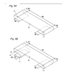
- a sewing form of the belt loop B to be sewn by the belt loop sewing apparatus 10 has the most basic sewing form (see Fig. 5A ) for folding back both ends inward each other and sewing the belt loop onto a bodice cloth or a sewing form (see Fig. 5B ) for folding one of the ends of the belt loop B in an almost Z shape, folding back the other end inward and sewing the belt loop onto the bodice cloth, for example.
- the operating unit 86 sets values, for example, a distance Ma from a seam L1 to an edge on one of ends of the belt loop B, a distance Mb from the seam L1 to a seam L2, a distance Md from the seam L1 to a fold-back part on one of the ends of the belt group B, a distance Me from the seam L2 to a fold-back part on the other end of the belt loop B, and a distance Mf from the seam L2 to an edge on the other end of the belt loop B.
- the operating unit 86 sets values, for example, a distance Ma from a seam L1 to an edge on one of the ends of the belt loop B, a distance Mb from a seam L2 to a seam L3, a distance Mc from the seam L1 to the seam L2, a distance Md from the seam L2 to a fold-back part of one of the ends of the belt loop B, a distance Me from a seam L3 to a fold-back part on the other end of the belt loop B, and a distance Mf from the seam L3 to an edge on the other end of the belt loop B.
- a control program for controlling each portion of the sewing machine to form a sewing pattern of each seam which is selected or a control parameter for defining an operating amount or operating order for each stitch which is required for carrying out bar tack or basting is preset to the ROM 82 or the EEPROM 84.
- a parameter for regulating the orientation or arrangement of the belt loop B to fold the end of the belt loop B back toward the central side of the belt loop B is input through the touch panel 87 of the operating unit 86.
- the loop clamp 31 there are set and input data on a moving amount and a moving direction for moving the loop clamp 31 interposing the belt loop B by a predetermined amount in the direction crossing the longitudinal direction of the belt loop B.
- the set data are recorded in the EEPROM 84 and are read and utilized in the control of the movement of the loop clamp.
- a belt loop forming step ST2 is executed through an operation of a completing switch (not shown) provided on the touch panel 87.
- the belt loop forming step ST2 controls an operation for cutting the belt loop B having a predetermined length from the long tape material, holding one of the ends of the belt loop B through the loop clamp 31 and folding back the other end by means of the fork unit 38 in the belt loop feeding apparatus 100.
- the loop holding pawl 66 of the loop pull-in portion 60b is caused to approach the vicinity of the send-out port of the loop send-out portion 60a through a driving operation of the pawl Y-axis motor 68, and furthermore, the loop holding pawl 66 of the loop pull-in portion 60b holds a tip b1 of the belt loop (tape material) B by the operation of the pawl air cylinder 67 (step S201).
- the loop holding pawl 66 is returned and moved in a standby position direction by the pawl Y-axis motor 68 and the held belt loop (tape material) B is pulled in toward the clamp unit 30 side (step S202).
- the belt loop (tape material) B is sent out by a predetermined length set in the various data setting step ST1 (Yes at step S203)
- the pawl Y-axis motor 68 is stopped (step S204).
- a pull-out amount of the belt loop (tape material) B is detected by an encoder 68A of the pawl Y-axis motor 68.
- the clamp X-axis motor 35 moves the holding block 32 forward, and furthermore, the clamp air cylinder 33 is operated to interpose the belt loop (tape material) B pulled in by means of the loop clamp 31 of the clamp unit 30 (step S205).
- the cutting air cylinder 64 is operated so that the belt loop (tape material) B is cut to have a predetermined length by means of the cutter 63 and the belt loop B having the predetermined length is thus obtained (step S206).
- the belt loop B has one of the ends (a tip portion) b1 held by the loop holding pawl 66 and has an intermediate part interposed by the loop clamp 31.
- the fork air cylinder 40 is operated to move the fork unit 38 forward (step S207) to bring a state in which a tip side of the belt loop B is inserted into the fork portion of the fork unit 38 (See Fig. 6A ).
- an operator of a sewing machine presets a regulating operation for eliminating the dog ear (a loop clamp moving control) to be valid or invalid, and furthermore, inputs and sets data on a parameter (a numeric value or a mark) related to a direction and a moving amount in order to move the loop clamp 31 interposing the belt loop B in such a direction that the end b1 of the belt loop B is assumed to be protruded in the X direction at the various data setting step (step ST1).
- a parameter a numeric value or a mark
- the loop clamp 31 is set to be moved by a predetermined length rightward in the drawing.
- the parameter represents a value decided to be valid for folding the end of the belt loop B by the operator depending on the orientation of the belt loop B recognized visually by the operator or the raw material of the belt loop B and may be an optional value.
- the loop clamp 31 interposing the belt loop B is moved by 2 mm in a rightward direction to regulate the orientation of the belt loop B in a state in which the loop holding pawl 66 holds the end b1 of the belt loop B (step S209).
- a fold-back operation is carried out (step S210).
- the rotary actuator 41 is operated to execute a folding control for rotating the fork unit 38 around the X axis, for example, in a normal direction.
- the air cylinder 67 for a pawl is operated to release the loop holding pawl 66. Consequently, the tip fork portion 38A pulls the end b1 of the belt loop B out of the loop holding pawl 66, and furthermore, the end b 1 of the belt loop B is folded back inward (downward in Fig. 6C ). Thus, it is possible to fold the end b1 of the belt loop B toward the central side of the belt loop B and to thus hold the end b1.
- controller 80 constitutes controller for controlling the rotation of the fork unit in order to fold one of the ends of the belt loop toward the central side of the belt loop.
- the belt loop B held by the loop clamp 31 and the fork unit 38 is moved in the direction crossing the longitudinal direction and is placed in a sewing position of the belt loop sewing machine 1 (step ST3).
- the X-axis motor 35 and the Y-axis motor 36 for a clamp move the holding block 32 to deliver the belt loop B to a sewing execution position of the cloth put on the throat plate 3 in a state in which the belt loop B having the end b 1 folded back is held by the loop clamp 31 and the fork unit 38 in the clamp unit 30.
- the belt loop B is disposed in such a manner that the vicinity of the end b1 is opposed to a vertical moving position of the needle 11.
- a sewing operation is started by a starting switching manipulation for the sewing operation through the operator so that a belt loop sewing step is executed (step ST4).
- the pulse motor 57 is operated so that the loop presser 52 is moved downward to press and hold the end b 1 of the belt loop B which is folded back and the cloth.
- the air cylinder 40 does not act so that the fork unit 38 is returned and moved backward to an initial position.
- the cloth feeding table 59 is moved by means of the X-axis motor 53 and the Y-axis motor 54 for the cloth, and furthermore, the driving source of the sewing machine body is subjected to an operation control so that the seam L1 having a predetermined number of stitches is formed and the end b1 of the belt loop B is thus sewn onto the cloth.
- the loop clamp 31 interposing the belt loop B is moved by a predetermined amount in such a direction that the end b1 is protruded and the direction of the belt loop B is regulated, and the end b1 of the belt loop B is folded back by the fork unit 38. Consequently, it is possible to fold the end b 1 of the belt loop B without the protrusion from the central side of the belt loop B.
- step S201 to step S210 it is also possible to advance the step through the switch manipulation by the operator without automatically executing the operation steps (step S201 to step S210).
- the seam L1 on the end side is formed and the end b1 is sewn onto the bodice cloth, and then, the loop clamp 31 once releases the belt loop B and is moved in the Y direction, and the other end of the belt loop B is interposed. Accordingly, the seam L1 serves as the loop holding pawl 66 in the fold-back of the one end side.
- the fork unit 38 is moved forward and stands by between the loop clamp 31 and the seam L1 in a state in which the belt loop B is inserted into the fork portion on the tip (see Fig. 7A ).
- the operator of the sewing machine previously selects a validity or an invalidity of the operation for regulating the other end or inputs and sets various parameters (data) for regulating the orientation and arrangement of the belt loop B in various data setting steps in the same manner as in the operation for regulating the end b1.
- the loop clamp 31 interposing the belt loop B is moved leftward by 2 mm to regulate the orientation of the belt loop B in a state in which the end side of the belt loop B is fixedly sewn onto the cloth ( Fig. 7B ).
- the rotary actuator 41 is then rotated in a reverse direction to reversely rotate the fork unit 38. Consequently, the other end b2 of the belt loop B is pulled out of the loop clamp 31 and the end b2 on the other end side of the belt loop B is folded back toward the end side of the belt loop B, and the other end b2 of the belt loop B is folded downward from the central side of the belt loop B as shown in Fig. 7C .
- the loop presser 52 is moved downward onto the portion thus obtained by folding the other end b2 back so that the other end b2 of the belt loop B which is folded back and the cloth are pressed and held. Moreover, the fork unit 38 is moved backward and the other end b2 is then pulled out of the belt loop B, and thereafter, each portion of the sewing machine is subjected to an operation control so that the seam L2 is sewn and the other end b2 of the belt loop B is sewn onto the cloth.
- the loop clamp 31 interposing the belt loop B is moved by a predetermined amount in a reverse direction to the protrusion assuming direction of the other end b1 to regulate the orientation of the belt loop B, and the other end b2 of the belt loop B is then folded back by the fork unit 38. Consequently, the other end b2 of the belt loop B can be folded back without the protrusion from the central side of the belt loop B.
- the fork unit 38 is rotated to fold the other end b2 of the belt loop B back toward the central side of the belt loop B without the execution of the loop clamp moving control.
- the other end b2 of the belt loop B which is folded back is protruded from the central side toward the left side, however, it is sufficient to execute the control for moving the loop clamp 31 rightward.
- the invention is not restricted to the embodiment.
- the arrangement of the end of the belt loop B dragged to follow the movement of the fork unit 38 is shifted so that the end is protruded from the central side of the belt loop B.
- a control for previously moving the loop clamp 31 rightward in the drawing is executed corresponding to the protrusion of the end b 1 of the belt loop B due to the dragging against the assumption that the end b 1 is dragged by the fork unit 38 moved backward in the X-axis direction, that is, toward the right side in the drawing and is thus protruded from the belt loop B rightward in the drawing.
- a control for previously moving the loop clamp 31 leftward in the drawing is executed corresponding to the protrusion of the other end b2 of the belt loop B due to the dragging against the assumption that the other end b2 is dragged by the fork unit 38 moved backward in the X-axis direction, that is, toward the right side in the drawing and is thus protruded from the belt loop B rightward in the drawing.
- the corrected parameter may be an optional value depending on a shift amount of the end dragged by the movement of the fork unit 38, for example, represents a value decided by the operator as to whether the raw material of the belt loop B easily follows the movement of the fork unit 38 or a value for correcting the shift after actual dragging.
- a corrected parameter is "zero" when the end of the belt loop B follows the movement of the fork unit 38 with difficulty and is not dragged.
- the belt loop feeding apparatus 100 includes the loop holding pawl 66 and a loop pull-in portion 60b as the holding unit.
- any holding unit (the loop holding pawl 66, the loop pull-in portion 60b) is not provided on the belt loop feeding apparatus 100.
- the holding unit (the loop holding pawl 66, the loop pull-in portion 60b) on the belt loop feeding apparatus 100 of the present invention.
Landscapes
- Engineering & Computer Science (AREA)
- Textile Engineering (AREA)
- Sewing Machines And Sewing (AREA)
Applications Claiming Priority (1)
| Application Number | Priority Date | Filing Date | Title |
|---|---|---|---|
| JP2010274353A JP5759158B2 (ja) | 2010-12-09 | 2010-12-09 | ベルトループ付けミシン及びベルトループの折り返し方法 |
Publications (3)
| Publication Number | Publication Date |
|---|---|
| EP2463429A2 true EP2463429A2 (fr) | 2012-06-13 |
| EP2463429A3 EP2463429A3 (fr) | 2015-05-27 |
| EP2463429B1 EP2463429B1 (fr) | 2016-10-26 |
Family
ID=45218416
Family Applications (1)
| Application Number | Title | Priority Date | Filing Date |
|---|---|---|---|
| EP11192509.5A Active EP2463429B1 (fr) | 2010-12-09 | 2011-12-08 | Appareil de couture de boucle de ceinture et procédé de commande correspondant |
Country Status (3)
| Country | Link |
|---|---|
| EP (1) | EP2463429B1 (fr) |
| JP (1) | JP5759158B2 (fr) |
| CN (1) | CN102535034B (fr) |
Cited By (1)
| Publication number | Priority date | Publication date | Assignee | Title |
|---|---|---|---|---|
| IT202100031679A1 (it) * | 2021-12-17 | 2023-06-17 | Vi Be Mac Spa | Capo d'abbigliamento con passanti per cintura e procedimento per realizzare un passante per cintura su un capo d'abbigliamento |
Families Citing this family (8)
| Publication number | Priority date | Publication date | Assignee | Title |
|---|---|---|---|---|
| CN103696184B (zh) * | 2014-01-09 | 2016-02-17 | 熊德元 | 一种电脑花样机 |
| JP6389665B2 (ja) * | 2014-07-15 | 2018-09-12 | Juki株式会社 | ベルトループ付けミシン及びベルトループ縫い付け方法 |
| CN104372536B (zh) * | 2014-11-22 | 2015-12-16 | 宁波舒普机电股份有限公司 | 一种织带机的叠料机构 |
| CN104480647B (zh) * | 2014-11-22 | 2016-03-02 | 宁波舒普机电股份有限公司 | 一种织带加工方法 |
| CN105986369B (zh) * | 2015-02-16 | 2020-05-01 | Juki株式会社 | 带环材料的缝合方法以及带环缝制缝纫机 |
| CN104727024B (zh) * | 2015-03-17 | 2017-12-15 | 深圳市德业自动化科技有限公司 | 一种用于多功能半自动织带缝纫机的拉环结构 |
| CN104762761B (zh) * | 2015-03-17 | 2017-03-29 | 深圳市德业智能股份有限公司 | 一种多功能半自动织带缝纫机 |
| CN105133206B (zh) * | 2015-09-22 | 2017-03-15 | 宁波舒普机电股份有限公司 | 一种具有折料结构的织带机 |
Citations (1)
| Publication number | Priority date | Publication date | Assignee | Title |
|---|---|---|---|---|
| JP2000167282A (ja) | 1998-12-10 | 2000-06-20 | Juki Corp | ベルトループ供給装置 |
Family Cites Families (12)
| Publication number | Priority date | Publication date | Assignee | Title |
|---|---|---|---|---|
| JP2649005B2 (ja) * | 1993-02-26 | 1997-09-03 | グンゼ株式会社 | テープ状生地の縫着方法 |
| JP4069268B2 (ja) * | 1999-03-19 | 2008-04-02 | Juki株式会社 | ベルトループ供給装置 |
| JP2000342873A (ja) * | 1999-03-29 | 2000-12-12 | Juki Corp | ベルトループ縫付けミシン |
| JP3988124B2 (ja) * | 2002-04-24 | 2007-10-10 | ブラザー工業株式会社 | 縫製装置用ベルトループ片供給装置 |
| JP5241406B2 (ja) * | 2008-09-25 | 2013-07-17 | Juki株式会社 | ループ材供給装置 |
| JP5410719B2 (ja) * | 2008-09-25 | 2014-02-05 | Juki株式会社 | ベルトループ縫いミシンの制御方法およびベルトループ縫いミシン |
| JP5372451B2 (ja) * | 2008-09-25 | 2013-12-18 | Juki株式会社 | ループ材供給装置 |
| JP5519137B2 (ja) * | 2008-09-25 | 2014-06-11 | Juki株式会社 | ベルトループ縫いミシンの制御装置およびベルトループ縫いミシンの制御方法 |
| JP5241405B2 (ja) * | 2008-09-25 | 2013-07-17 | Juki株式会社 | ループ材供給装置 |
| JP2010110624A (ja) * | 2008-10-10 | 2010-05-20 | Juki Corp | ベルトループ縫いミシンの制御方法およびベルトループ縫いミシン |
| JP5616587B2 (ja) * | 2009-04-16 | 2014-10-29 | Juki株式会社 | ベルトループ付けミシン |
| JP5689590B2 (ja) * | 2009-05-18 | 2015-03-25 | Juki株式会社 | ミシン |
-
2010
- 2010-12-09 JP JP2010274353A patent/JP5759158B2/ja not_active Expired - Fee Related
-
2011
- 2011-12-08 EP EP11192509.5A patent/EP2463429B1/fr active Active
- 2011-12-09 CN CN201110408285.9A patent/CN102535034B/zh active Active
Patent Citations (1)
| Publication number | Priority date | Publication date | Assignee | Title |
|---|---|---|---|---|
| JP2000167282A (ja) | 1998-12-10 | 2000-06-20 | Juki Corp | ベルトループ供給装置 |
Cited By (1)
| Publication number | Priority date | Publication date | Assignee | Title |
|---|---|---|---|---|
| IT202100031679A1 (it) * | 2021-12-17 | 2023-06-17 | Vi Be Mac Spa | Capo d'abbigliamento con passanti per cintura e procedimento per realizzare un passante per cintura su un capo d'abbigliamento |
Also Published As
| Publication number | Publication date |
|---|---|
| JP5759158B2 (ja) | 2015-08-05 |
| CN102535034A (zh) | 2012-07-04 |
| EP2463429A3 (fr) | 2015-05-27 |
| CN102535034B (zh) | 2015-04-22 |
| EP2463429B1 (fr) | 2016-10-26 |
| JP2012120730A (ja) | 2012-06-28 |
Similar Documents
| Publication | Publication Date | Title |
|---|---|---|
| EP2463429B1 (fr) | Appareil de couture de boucle de ceinture et procédé de commande correspondant | |
| JP5993162B2 (ja) | ミシン | |
| JP5616587B2 (ja) | ベルトループ付けミシン | |
| JP5410719B2 (ja) | ベルトループ縫いミシンの制御方法およびベルトループ縫いミシン | |
| JP4903598B2 (ja) | 玉縁縫いミシン | |
| CN105986369B (zh) | 带环材料的缝合方法以及带环缝制缝纫机 | |
| JP5253947B2 (ja) | ベルトループ縫いミシン | |
| CN102877219B (zh) | 带环缝制缝纫机 | |
| JP4573658B2 (ja) | 玉縁縫いミシン | |
| JP5468222B2 (ja) | 玉縁縫いミシン | |
| JP5965645B2 (ja) | ベルトループ縫い付け方法及びベルトループ付けミシン | |
| JP2005130888A (ja) | 自動縫製装置 | |
| JP5519137B2 (ja) | ベルトループ縫いミシンの制御装置およびベルトループ縫いミシンの制御方法 | |
| JP2007195806A (ja) | 自動玉縁縫いミシン | |
| JP5142454B2 (ja) | ミシン | |
| JP4960008B2 (ja) | 玉縁縫いミシン | |
| JP2010110624A (ja) | ベルトループ縫いミシンの制御方法およびベルトループ縫いミシン | |
| JP4603930B2 (ja) | 布保持具 | |
| JP2007089987A (ja) | 玉縁縫いミシン | |
| JP5241244B2 (ja) | 玉縁縫いミシン | |
| EP2149310A2 (fr) | Machine à border | |
| TWI656255B (zh) | Embroidery sewing machine with fixed function of false lining and material | |
| JP6530243B2 (ja) | 玉縁縫いミシン | |
| EP2154282A2 (fr) | Mécanisme de couteau d'arête d'une machine à couteaux circulaires |
Legal Events
| Date | Code | Title | Description |
|---|---|---|---|
| PUAI | Public reference made under article 153(3) epc to a published international application that has entered the european phase |
Free format text: ORIGINAL CODE: 0009012 |
|
| AK | Designated contracting states |
Kind code of ref document: A2 Designated state(s): AL AT BE BG CH CY CZ DE DK EE ES FI FR GB GR HR HU IE IS IT LI LT LU LV MC MK MT NL NO PL PT RO RS SE SI SK SM TR |
|
| AX | Request for extension of the european patent |
Extension state: BA ME |
|
| PUAL | Search report despatched |
Free format text: ORIGINAL CODE: 0009013 |
|
| AK | Designated contracting states |
Kind code of ref document: A3 Designated state(s): AL AT BE BG CH CY CZ DE DK EE ES FI FR GB GR HR HU IE IS IT LI LT LU LV MC MK MT NL NO PL PT RO RS SE SI SK SM TR |
|
| AX | Request for extension of the european patent |
Extension state: BA ME |
|
| RIC1 | Information provided on ipc code assigned before grant |
Ipc: D05B 35/06 20060101AFI20150422BHEP |
|
| 17P | Request for examination filed |
Effective date: 20151127 |
|
| RBV | Designated contracting states (corrected) |
Designated state(s): AL AT BE BG CH CY CZ DE DK EE ES FI FR GB GR HR HU IE IS IT LI LT LU LV MC MK MT NL NO PL PT RO RS SE SI SK SM TR |
|
| GRAP | Despatch of communication of intention to grant a patent |
Free format text: ORIGINAL CODE: EPIDOSNIGR1 |
|
| INTG | Intention to grant announced |
Effective date: 20160509 |
|
| GRAS | Grant fee paid |
Free format text: ORIGINAL CODE: EPIDOSNIGR3 |
|
| GRAA | (expected) grant |
Free format text: ORIGINAL CODE: 0009210 |
|
| AK | Designated contracting states |
Kind code of ref document: B1 Designated state(s): AL AT BE BG CH CY CZ DE DK EE ES FI FR GB GR HR HU IE IS IT LI LT LU LV MC MK MT NL NO PL PT RO RS SE SI SK SM TR |
|
| REG | Reference to a national code |
Ref country code: GB Ref legal event code: FG4D |
|
| REG | Reference to a national code |
Ref country code: CH Ref legal event code: EP |
|
| REG | Reference to a national code |
Ref country code: AT Ref legal event code: REF Ref document number: 840114 Country of ref document: AT Kind code of ref document: T Effective date: 20161115 |
|
| REG | Reference to a national code |
Ref country code: IE Ref legal event code: FG4D |
|
| REG | Reference to a national code |
Ref country code: DE Ref legal event code: R096 Ref document number: 602011031625 Country of ref document: DE |
|
| REG | Reference to a national code |
Ref country code: LT Ref legal event code: MG4D |
|
| PG25 | Lapsed in a contracting state [announced via postgrant information from national office to epo] |
Ref country code: LV Free format text: LAPSE BECAUSE OF FAILURE TO SUBMIT A TRANSLATION OF THE DESCRIPTION OR TO PAY THE FEE WITHIN THE PRESCRIBED TIME-LIMIT Effective date: 20161026 |
|
| REG | Reference to a national code |
Ref country code: NL Ref legal event code: MP Effective date: 20161026 |
|
| REG | Reference to a national code |
Ref country code: AT Ref legal event code: MK05 Ref document number: 840114 Country of ref document: AT Kind code of ref document: T Effective date: 20161026 |
|
| PG25 | Lapsed in a contracting state [announced via postgrant information from national office to epo] |
Ref country code: LT Free format text: LAPSE BECAUSE OF FAILURE TO SUBMIT A TRANSLATION OF THE DESCRIPTION OR TO PAY THE FEE WITHIN THE PRESCRIBED TIME-LIMIT Effective date: 20161026 Ref country code: GR Free format text: LAPSE BECAUSE OF FAILURE TO SUBMIT A TRANSLATION OF THE DESCRIPTION OR TO PAY THE FEE WITHIN THE PRESCRIBED TIME-LIMIT Effective date: 20170127 Ref country code: SE Free format text: LAPSE BECAUSE OF FAILURE TO SUBMIT A TRANSLATION OF THE DESCRIPTION OR TO PAY THE FEE WITHIN THE PRESCRIBED TIME-LIMIT Effective date: 20161026 Ref country code: NO Free format text: LAPSE BECAUSE OF FAILURE TO SUBMIT A TRANSLATION OF THE DESCRIPTION OR TO PAY THE FEE WITHIN THE PRESCRIBED TIME-LIMIT Effective date: 20170126 |
|
| PG25 | Lapsed in a contracting state [announced via postgrant information from national office to epo] |
Ref country code: IS Free format text: LAPSE BECAUSE OF FAILURE TO SUBMIT A TRANSLATION OF THE DESCRIPTION OR TO PAY THE FEE WITHIN THE PRESCRIBED TIME-LIMIT Effective date: 20170226 Ref country code: HR Free format text: LAPSE BECAUSE OF FAILURE TO SUBMIT A TRANSLATION OF THE DESCRIPTION OR TO PAY THE FEE WITHIN THE PRESCRIBED TIME-LIMIT Effective date: 20161026 Ref country code: RS Free format text: LAPSE BECAUSE OF FAILURE TO SUBMIT A TRANSLATION OF THE DESCRIPTION OR TO PAY THE FEE WITHIN THE PRESCRIBED TIME-LIMIT Effective date: 20161026 Ref country code: PL Free format text: LAPSE BECAUSE OF FAILURE TO SUBMIT A TRANSLATION OF THE DESCRIPTION OR TO PAY THE FEE WITHIN THE PRESCRIBED TIME-LIMIT Effective date: 20161026 Ref country code: NL Free format text: LAPSE BECAUSE OF FAILURE TO SUBMIT A TRANSLATION OF THE DESCRIPTION OR TO PAY THE FEE WITHIN THE PRESCRIBED TIME-LIMIT Effective date: 20161026 Ref country code: BE Free format text: LAPSE BECAUSE OF FAILURE TO SUBMIT A TRANSLATION OF THE DESCRIPTION OR TO PAY THE FEE WITHIN THE PRESCRIBED TIME-LIMIT Effective date: 20161026 Ref country code: FI Free format text: LAPSE BECAUSE OF FAILURE TO SUBMIT A TRANSLATION OF THE DESCRIPTION OR TO PAY THE FEE WITHIN THE PRESCRIBED TIME-LIMIT Effective date: 20161026 Ref country code: AT Free format text: LAPSE BECAUSE OF FAILURE TO SUBMIT A TRANSLATION OF THE DESCRIPTION OR TO PAY THE FEE WITHIN THE PRESCRIBED TIME-LIMIT Effective date: 20161026 Ref country code: ES Free format text: LAPSE BECAUSE OF FAILURE TO SUBMIT A TRANSLATION OF THE DESCRIPTION OR TO PAY THE FEE WITHIN THE PRESCRIBED TIME-LIMIT Effective date: 20161026 Ref country code: PT Free format text: LAPSE BECAUSE OF FAILURE TO SUBMIT A TRANSLATION OF THE DESCRIPTION OR TO PAY THE FEE WITHIN THE PRESCRIBED TIME-LIMIT Effective date: 20170227 |
|
| REG | Reference to a national code |
Ref country code: DE Ref legal event code: R097 Ref document number: 602011031625 Country of ref document: DE |
|
| PG25 | Lapsed in a contracting state [announced via postgrant information from national office to epo] |
Ref country code: RO Free format text: LAPSE BECAUSE OF FAILURE TO SUBMIT A TRANSLATION OF THE DESCRIPTION OR TO PAY THE FEE WITHIN THE PRESCRIBED TIME-LIMIT Effective date: 20161026 Ref country code: DK Free format text: LAPSE BECAUSE OF FAILURE TO SUBMIT A TRANSLATION OF THE DESCRIPTION OR TO PAY THE FEE WITHIN THE PRESCRIBED TIME-LIMIT Effective date: 20161026 Ref country code: CZ Free format text: LAPSE BECAUSE OF FAILURE TO SUBMIT A TRANSLATION OF THE DESCRIPTION OR TO PAY THE FEE WITHIN THE PRESCRIBED TIME-LIMIT Effective date: 20161026 Ref country code: EE Free format text: LAPSE BECAUSE OF FAILURE TO SUBMIT A TRANSLATION OF THE DESCRIPTION OR TO PAY THE FEE WITHIN THE PRESCRIBED TIME-LIMIT Effective date: 20161026 Ref country code: SK Free format text: LAPSE BECAUSE OF FAILURE TO SUBMIT A TRANSLATION OF THE DESCRIPTION OR TO PAY THE FEE WITHIN THE PRESCRIBED TIME-LIMIT Effective date: 20161026 |
|
| REG | Reference to a national code |
Ref country code: CH Ref legal event code: PL |
|
| PG25 | Lapsed in a contracting state [announced via postgrant information from national office to epo] |
Ref country code: BG Free format text: LAPSE BECAUSE OF FAILURE TO SUBMIT A TRANSLATION OF THE DESCRIPTION OR TO PAY THE FEE WITHIN THE PRESCRIBED TIME-LIMIT Effective date: 20170126 Ref country code: IT Free format text: LAPSE BECAUSE OF FAILURE TO SUBMIT A TRANSLATION OF THE DESCRIPTION OR TO PAY THE FEE WITHIN THE PRESCRIBED TIME-LIMIT Effective date: 20161026 Ref country code: SM Free format text: LAPSE BECAUSE OF FAILURE TO SUBMIT A TRANSLATION OF THE DESCRIPTION OR TO PAY THE FEE WITHIN THE PRESCRIBED TIME-LIMIT Effective date: 20161026 |
|
| PLBE | No opposition filed within time limit |
Free format text: ORIGINAL CODE: 0009261 |
|
| STAA | Information on the status of an ep patent application or granted ep patent |
Free format text: STATUS: NO OPPOSITION FILED WITHIN TIME LIMIT |
|
| GBPC | Gb: european patent ceased through non-payment of renewal fee |
Effective date: 20170126 |
|
| PG25 | Lapsed in a contracting state [announced via postgrant information from national office to epo] |
Ref country code: MC Free format text: LAPSE BECAUSE OF FAILURE TO SUBMIT A TRANSLATION OF THE DESCRIPTION OR TO PAY THE FEE WITHIN THE PRESCRIBED TIME-LIMIT Effective date: 20161026 |
|
| REG | Reference to a national code |
Ref country code: FR Ref legal event code: ST Effective date: 20170831 |
|
| 26N | No opposition filed |
Effective date: 20170727 |
|
| REG | Reference to a national code |
Ref country code: IE Ref legal event code: MM4A |
|
| PG25 | Lapsed in a contracting state [announced via postgrant information from national office to epo] |
Ref country code: CH Free format text: LAPSE BECAUSE OF NON-PAYMENT OF DUE FEES Effective date: 20161231 Ref country code: LU Free format text: LAPSE BECAUSE OF NON-PAYMENT OF DUE FEES Effective date: 20161208 Ref country code: FR Free format text: LAPSE BECAUSE OF NON-PAYMENT OF DUE FEES Effective date: 20170102 Ref country code: LI Free format text: LAPSE BECAUSE OF NON-PAYMENT OF DUE FEES Effective date: 20161231 |
|
| PG25 | Lapsed in a contracting state [announced via postgrant information from national office to epo] |
Ref country code: IE Free format text: LAPSE BECAUSE OF NON-PAYMENT OF DUE FEES Effective date: 20161208 Ref country code: SI Free format text: LAPSE BECAUSE OF FAILURE TO SUBMIT A TRANSLATION OF THE DESCRIPTION OR TO PAY THE FEE WITHIN THE PRESCRIBED TIME-LIMIT Effective date: 20161026 Ref country code: GB Free format text: LAPSE BECAUSE OF NON-PAYMENT OF DUE FEES Effective date: 20170126 |
|
| PG25 | Lapsed in a contracting state [announced via postgrant information from national office to epo] |
Ref country code: CY Free format text: LAPSE BECAUSE OF FAILURE TO SUBMIT A TRANSLATION OF THE DESCRIPTION OR TO PAY THE FEE WITHIN THE PRESCRIBED TIME-LIMIT Effective date: 20161026 Ref country code: HU Free format text: LAPSE BECAUSE OF FAILURE TO SUBMIT A TRANSLATION OF THE DESCRIPTION OR TO PAY THE FEE WITHIN THE PRESCRIBED TIME-LIMIT; INVALID AB INITIO Effective date: 20111208 |
|
| PG25 | Lapsed in a contracting state [announced via postgrant information from national office to epo] |
Ref country code: TR Free format text: LAPSE BECAUSE OF FAILURE TO SUBMIT A TRANSLATION OF THE DESCRIPTION OR TO PAY THE FEE WITHIN THE PRESCRIBED TIME-LIMIT Effective date: 20161026 Ref country code: MK Free format text: LAPSE BECAUSE OF FAILURE TO SUBMIT A TRANSLATION OF THE DESCRIPTION OR TO PAY THE FEE WITHIN THE PRESCRIBED TIME-LIMIT Effective date: 20161026 |
|
| PG25 | Lapsed in a contracting state [announced via postgrant information from national office to epo] |
Ref country code: MT Free format text: LAPSE BECAUSE OF NON-PAYMENT OF DUE FEES Effective date: 20161208 |
|
| PG25 | Lapsed in a contracting state [announced via postgrant information from national office to epo] |
Ref country code: AL Free format text: LAPSE BECAUSE OF FAILURE TO SUBMIT A TRANSLATION OF THE DESCRIPTION OR TO PAY THE FEE WITHIN THE PRESCRIBED TIME-LIMIT Effective date: 20161026 |
|
| PGFP | Annual fee paid to national office [announced via postgrant information from national office to epo] |
Ref country code: DE Payment date: 20251028 Year of fee payment: 15 |