EP2463494A2 - Vorrichtung eines Kühlsystems für ein Fahrzeug und Steuerverfahren damit - Google Patents
Vorrichtung eines Kühlsystems für ein Fahrzeug und Steuerverfahren damit Download PDFInfo
- Publication number
- EP2463494A2 EP2463494A2 EP11190078A EP11190078A EP2463494A2 EP 2463494 A2 EP2463494 A2 EP 2463494A2 EP 11190078 A EP11190078 A EP 11190078A EP 11190078 A EP11190078 A EP 11190078A EP 2463494 A2 EP2463494 A2 EP 2463494A2
- Authority
- EP
- European Patent Office
- Prior art keywords
- temperature
- coolant
- oil
- cooling system
- high temperature
- Prior art date
- Legal status (The legal status is an assumption and is not a legal conclusion. Google has not performed a legal analysis and makes no representation as to the accuracy of the status listed.)
- Granted
Links
- 238000001816 cooling Methods 0.000 title claims abstract description 89
- 238000000034 method Methods 0.000 title claims abstract description 9
- 239000002826 coolant Substances 0.000 claims abstract description 137
- 230000007613 environmental effect Effects 0.000 claims abstract description 20
- 238000005461 lubrication Methods 0.000 claims abstract description 13
- XLYOFNOQVPJJNP-UHFFFAOYSA-N water Substances O XLYOFNOQVPJJNP-UHFFFAOYSA-N 0.000 claims abstract description 12
- 239000003921 oil Substances 0.000 claims description 70
- 230000005540 biological transmission Effects 0.000 claims description 48
- 239000010705 motor oil Substances 0.000 claims description 42
- 239000000446 fuel Substances 0.000 description 10
- 238000012986 modification Methods 0.000 description 3
- 230000004048 modification Effects 0.000 description 3
- 230000003247 decreasing effect Effects 0.000 description 2
- 238000010586 diagram Methods 0.000 description 2
- 239000012208 gear oil Substances 0.000 description 2
- 230000010354 integration Effects 0.000 description 2
- 238000010792 warming Methods 0.000 description 2
- 230000001133 acceleration Effects 0.000 description 1
- 238000002485 combustion reaction Methods 0.000 description 1
- 230000000694 effects Effects 0.000 description 1
- 230000020169 heat generation Effects 0.000 description 1
- 238000013021 overheating Methods 0.000 description 1
Images


Classifications
-
- F—MECHANICAL ENGINEERING; LIGHTING; HEATING; WEAPONS; BLASTING
- F01—MACHINES OR ENGINES IN GENERAL; ENGINE PLANTS IN GENERAL; STEAM ENGINES
- F01P—COOLING OF MACHINES OR ENGINES IN GENERAL; COOLING OF INTERNAL-COMBUSTION ENGINES
- F01P7/00—Controlling of coolant flow
- F01P7/14—Controlling of coolant flow the coolant being liquid
- F01P7/16—Controlling of coolant flow the coolant being liquid by thermostatic control
- F01P7/165—Controlling of coolant flow the coolant being liquid by thermostatic control characterised by systems with two or more loops
-
- F—MECHANICAL ENGINEERING; LIGHTING; HEATING; WEAPONS; BLASTING
- F02—COMBUSTION ENGINES; HOT-GAS OR COMBUSTION-PRODUCT ENGINE PLANTS
- F02B—INTERNAL-COMBUSTION PISTON ENGINES; COMBUSTION ENGINES IN GENERAL
- F02B29/00—Engines characterised by provision for charging or scavenging not provided for in groups F02B25/00, F02B27/00 or F02B33/00 - F02B39/00; Details thereof
- F02B29/04—Cooling of air intake supply
- F02B29/0406—Layout of the intake air cooling or coolant circuit
- F02B29/0437—Liquid cooled heat exchangers
- F02B29/0443—Layout of the coolant or refrigerant circuit
-
- F—MECHANICAL ENGINEERING; LIGHTING; HEATING; WEAPONS; BLASTING
- F01—MACHINES OR ENGINES IN GENERAL; ENGINE PLANTS IN GENERAL; STEAM ENGINES
- F01P—COOLING OF MACHINES OR ENGINES IN GENERAL; COOLING OF INTERNAL-COMBUSTION ENGINES
- F01P2060/00—Cooling circuits using auxiliaries
- F01P2060/02—Intercooler
-
- F—MECHANICAL ENGINEERING; LIGHTING; HEATING; WEAPONS; BLASTING
- F01—MACHINES OR ENGINES IN GENERAL; ENGINE PLANTS IN GENERAL; STEAM ENGINES
- F01P—COOLING OF MACHINES OR ENGINES IN GENERAL; COOLING OF INTERNAL-COMBUSTION ENGINES
- F01P2060/00—Cooling circuits using auxiliaries
- F01P2060/04—Lubricant cooler
-
- F—MECHANICAL ENGINEERING; LIGHTING; HEATING; WEAPONS; BLASTING
- F01—MACHINES OR ENGINES IN GENERAL; ENGINE PLANTS IN GENERAL; STEAM ENGINES
- F01P—COOLING OF MACHINES OR ENGINES IN GENERAL; COOLING OF INTERNAL-COMBUSTION ENGINES
- F01P2060/00—Cooling circuits using auxiliaries
- F01P2060/08—Cabin heater
-
- F—MECHANICAL ENGINEERING; LIGHTING; HEATING; WEAPONS; BLASTING
- F02—COMBUSTION ENGINES; HOT-GAS OR COMBUSTION-PRODUCT ENGINE PLANTS
- F02M—SUPPLYING COMBUSTION ENGINES IN GENERAL WITH COMBUSTIBLE MIXTURES OR CONSTITUENTS THEREOF
- F02M26/00—Engine-pertinent apparatus for adding exhaust gases to combustion-air, main fuel or fuel-air mixture, e.g. by exhaust gas recirculation [EGR] systems
- F02M26/13—Arrangement or layout of EGR passages, e.g. in relation to specific engine parts or for incorporation of accessories
- F02M26/22—Arrangement or layout of EGR passages, e.g. in relation to specific engine parts or for incorporation of accessories with coolers in the recirculation passage
- F02M26/23—Layout, e.g. schematics
- F02M26/24—Layout, e.g. schematics with two or more coolers
-
- F—MECHANICAL ENGINEERING; LIGHTING; HEATING; WEAPONS; BLASTING
- F02—COMBUSTION ENGINES; HOT-GAS OR COMBUSTION-PRODUCT ENGINE PLANTS
- F02M—SUPPLYING COMBUSTION ENGINES IN GENERAL WITH COMBUSTIBLE MIXTURES OR CONSTITUENTS THEREOF
- F02M26/00—Engine-pertinent apparatus for adding exhaust gases to combustion-air, main fuel or fuel-air mixture, e.g. by exhaust gas recirculation [EGR] systems
- F02M26/13—Arrangement or layout of EGR passages, e.g. in relation to specific engine parts or for incorporation of accessories
- F02M26/22—Arrangement or layout of EGR passages, e.g. in relation to specific engine parts or for incorporation of accessories with coolers in the recirculation passage
- F02M26/23—Layout, e.g. schematics
- F02M26/28—Layout, e.g. schematics with liquid-cooled heat exchangers
-
- Y—GENERAL TAGGING OF NEW TECHNOLOGICAL DEVELOPMENTS; GENERAL TAGGING OF CROSS-SECTIONAL TECHNOLOGIES SPANNING OVER SEVERAL SECTIONS OF THE IPC; TECHNICAL SUBJECTS COVERED BY FORMER USPC CROSS-REFERENCE ART COLLECTIONS [XRACs] AND DIGESTS
- Y02—TECHNOLOGIES OR APPLICATIONS FOR MITIGATION OR ADAPTATION AGAINST CLIMATE CHANGE
- Y02T—CLIMATE CHANGE MITIGATION TECHNOLOGIES RELATED TO TRANSPORTATION
- Y02T10/00—Road transport of goods or passengers
- Y02T10/10—Internal combustion engine [ICE] based vehicles
- Y02T10/12—Improving ICE efficiencies
Definitions
- the present invention relates to a cooling system of a vehicle, and more particularly relates to a vehicle cooling system that considers environmental elements and driving elements to control a cooling system and a lubrication system so as to effectively use heat energy that is wasted in a conventional art and the control method using the same.
- an engine and a transmission of a vehicle is operated in a high temperature, or a range of high temperatures, that is formed by combustion of fuel and friction of each components.
- Coolant passages are formed to cool the hot engine and transmission, and a thermostat 40 is provided to change the coolant passage so as to quickly warm up the cold engine.
- a radiator is disposed to cool the heat of the coolant.
- a cooling fan is disposed to increase heat exchanging amount of the radiator.
- an engine consumes smaller amount of fuel in a warm condition compared to that in a cold condition, and therefore a fast warming up improves fuel efficiency. Also, if the engine is operated in a high temperature regardless of the durability of the engine, the fuel consumption efficiency can be increased.
- Engine oil and transmission oil are used to lubricate the engine and the transmission, the lubrication oil contacting sliding portions of the engine and the transmission has a low friction characteristic in a high temperature and has a high friction characteristic in a low temperature, and the low friction characteristic improves the fuel consumption efficiency.
- the sliding components can be damaged by a mechanical contact, and a heat exchanger is disposed to prevent the over heat of the oil.
- the heat exchanger can excessively lower a temperature of the lubrication oil in cases when an outside temperature is low, it's raining, a load of an engine is low, or a vehicle speed is low such that viscosity of the lubrication oil is increased and there is a side effect that a power is lost by the increased viscosity.
- Exemplary cooling systems may include a high temperature radiator that cools a high temperature coolant circulating an engine, a low temperature radiator that cools a low temperature coolant passing a water cooled intercooler and a low exhaust gas recirculation (EGR) cooler of a turbo charger, a cooling fan that blows air to the high temperature radiator and the low temperature radiator, a high temperature coolant pump that pumps the high temperature coolant, a low temperature coolant pump that pumps the low temperature coolant, and a control portion that controls the high temperature coolant pump, the low temperature coolant pump, and the cooling fan according to driving conditions of the vehicle and environmental conditions.
- EGR exhaust gas recirculation
- Exemplary cooling systems may further include a transmission oil heat exchanger through which the high temperature coolant passes, a transmission pump that circulates a transmission oil through the transmission oil heat exchanger, an axle oil heat exchanger through which the high temperature coolant passes, and an axle pump that circulates an axle oil through the axle oil heat exchanger.
- the transmission pump and the axle pump may be hydraulic pumps.
- the control portion may operate the transmission pump to warm up the transmission oil if it is determined that a temperature of the transmission oil is low, and/or operate the axle pump to warm up the axle oil if it is determined that a temperature of the axle oil is low.
- the control portion may increase a flow rate of the low temperature coolant if a temperature of the low temperature coolant is equal to or higher than a first predetermined value, open an electric thermostat when a temperature of the high temperature coolant is equal to or higher than a predetermined thermostat opening temperature, and close the electric thermostat when the temperature of the high temperature coolant is less than a predetermined thermostat closing temperature.
- the thermostat closing temperature may be a few degrees lower than the thermostat opening temperature.
- the control portion may detect a temperature of an engine oil, make the engine oil pass an oil cooler when the engine oil temperature is equal to or higher than a second predetermined value, and make the engine oil bypass the oil cooler when the engine oil temperature is less than the second predetermined value.
- the control portion may operate the cooling fan at a first speed if a temperature of the high temperature coolant is equal to or higher than a third predetermined value, and operate the cooling fan at a second speed faster than the first speed if the high temperature coolant is not cooled by the first speed.
- the control portion may operate the low temperature coolant pump based on a base map of the low temperature coolant pump and compensates the base map of the low temperature coolant pump according to the speed of the cooling fan to control the low temperature coolant pump.
- the control portion may operate the high temperature coolant pump based on a base map of the high temperature coolant pump, and compensates the base map of the high temperature coolant pump according to the speed of the cooling fan to control the high temperature coolant pump.
- the control portion may control the speed of the cooling fan according to the outside temperature or the rainfall conditions.
- the controlling method using exemplary cooling systems according to the present invention may include detecting driving conditions of the vehicle and environmental conditions, setting an operating target for the cooling system and/or a lubrication system based on the driving conditions and the environmental conditions, and determining operating conditions for the cooling system and/or the lubrication system.
- the driving conditions being detected may include a low coolant temperature, a high coolant temperature, an engine oil temperature, a transmission oil temperature, an engine speed, an accelerator pedal position, and/or a vehicle speed.
- the environmental conditions being detected may include an intake air temperature, an outside temperature, and/or weather conditions.
- the operating conditions being determined may include a cooling fan speed, opening/closing of an electric thermostat, controls of the pumps, and/or coolant flow rates.
- the engine, the transmission, the differential gear oil temperature, and so on are optimally controlled to reduce a friction of the driving train and a fuel consumption rate, the heat that is wasted by the cooling fan, the water pump, and the auxiliary portions are efficiently managed and a power for cooling system is reduced such that a fuel consumption rate of the vehicle is decreased.
- FIG. 1 is a schematic diagram of an exemplary vehicle cooling system according to the present invention.
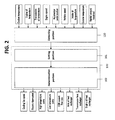
- FIG. 2 is a block diagram of an exemplary cooling system integration control according to the present invention.
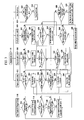
- FIG. 3 is a flow chart of an exemplary vehicle cooling system integration control according to the present invention.
- FIG. 4 is a flow chart of an exemplary engine coolant temperature control according to the present invention.
- FIG. 5 is a flow chart of a bypass valve control of an exemplary engine oil cooler according to the present invention.
- FIG. 6 is a flow chart of an exemplary gear oil warming control according to the present invention.
- FIG. 7 is a flow chart for controlling an exemplary low temperature coolant pump according to the present invention.
- a cooling system of a vehicle includes a low temperature radiator 20, a high temperature radiator 22, a cooling fan 30, a high temperature coolant pump 106, a low temperature coolant pump 108, an oil filter 11, a first oil control valve 110, an engine hydraulic pump 112, a second oil control valve 114, a transmission 60, a transmission hydraulic pump 64, a transmission oil heat exchanger 62, an axle hydraulic pump 74, an axle 70, an axle oil heat exchanger 72, a HAVC heater 128, a HAVC valve 130, an engine oil cooler 15, a turbocharger 132, a water cooled intercooler 134, a low temperature coolant valve 136, a cylinder block 12, a low temperature exhaust gas recirculation (EGR) cooler 138, a high temperature EGR cooler 140, and electric thermostat 40.
- EGR exhaust gas recirculation
- a low temperature coolant circulates the low temperature radiator 20, the low temperature coolant pump 108, the water cooled intercooler 134, and the low temperature EGR cooler 138.
- a high temperature coolant circulates the high temperature radiator 22, the high temperature coolant pump 106, the cylinder block 12, the high temperature EGR cooler 140, the HAVC heater 128, the transmission oil heat exchanger 62, and the axle oil heat exchanger 72.
- the engine oil circulates the engine hydraulic pump 112, the engine oil cooler 15, and the cylinder block 12 and bypasses the engine oil cooler 15 through the bypass line 16 depending on a temperature of the engine oil.
- the first and second oil control valve 110 and 114 bypasses the engine engine oil.
- Various embodiments of the present invention provide a vehicle cooling system to efficiently use the heat that is wasted from the cooling system of the vehicle.
- the electric thermostat 40 of the cooling system is an electrical device to change the opening rate of the thermostat 40 so as to control the coolant flow rate precisely such that the coolant temperature is maintained at a high level.
- the cooling fan 30 is equipped with a clutch, such as a magnetic clutch, to control operating speed thereof and finds an efficient operating speed range according to a high temperature or a low temperature of the coolant. As shown in FIG. 4 and FIG. 3 , the cooling fan 30 is connected to the high temperature coolant pump 106 and the electric thermostat 40 to adjust the operating speed in a few steps depending on the coolant temperature such that the consumption power of the engine is reduced.
- a clutch such as a magnetic clutch
- a bypass line 16 is disposed around the engine oil cooler 15, a solenoid valve 114 is disposed on the bypass line 16, and the solenoid valves 110 and 114 are controlled by a controller to be operated according to the engine oil temperature such that the engine oil temperature is maintained uniformly.
- the engine oil is controlled to be at a high temperature or a range of high temperatures; the temperature is accurately controlled while the engine operating state is being changed and the engine is quickly warmed up.
- the transmission oil heat exchanger 62 and the axle oil heat exchanger 72 are disposed on the coolant line, and a transmission hydraulic pump and an axle hydraulic pump 64 and 74 circulates the oil so as to quickly warm up the transmission oil and the axle oil.
- an exemplary integrated controller includes a detecting step that detects a driving condition or conditions and an environmental element or elements of a vehicle through a detecting portion 120, a setting step that sets an operating target of a cooling system and lubrication system according to the driving condition and the environmental condition through a setting portion 101, and a determination step that determines an operating condition of the cooling system through the determination portion 102.
- a detecting portion 120 detects the driving condition and the environmental condition of the vehicle.
- the detecting portion 120 can be sensors sensing all kinds of conditions, especially the detecting portion 120 detects a coolant temperature, an engine oil temperature, a transmission oil temperature, an engine speed, an acceleration pedal position, a vehicle speed, an outside temperature, rainfall, etc., and the position of the accelerator pedal is used to determine a power load that is applied to the engine.
- the integrated controller 100 receives the signal or signals from the detecting portion 120 to control the cooling system and the lubrication system according to the driving condition and the environmental condition of the vehicle.
- the integrated controller 100 sets a coolant temperature, an engine oil temperature, and a transmission oil temperature according to the driving condition and the environmental condition of the vehicle, performs a setting step that determines a control amount for each control element thereby, and determines whether the control elements is to be controlled.
- the control temperature and the control amount of each element are varied according to a vehicle speed, an engine load, an outside temperature, and a rainfall condition in the setting step. For example, if the vehicle moves in a high speed, the cooling air passing the radiator is increased such that the operating speed of the cooling fan 30 can be decreased. Like the preceding, while the outside temperature is low in winter or it is raining, the cooling becomes easy, and it is not a big problem to maintain the control temperature at a high value.
- the engine coolant temperature is varied by a control speed of the high temperature coolant water pump 106 according to the driving condition and the environmental condition, and the thermostat 40 is operated in a case that the coolant temperature is higher than an operating temperature for operating the thermostat 40 to increase the cooling capacity of the radiator.
- the cooling fan 30 is operated to lower the coolant temperature.
- the transmission oil temperature is warmed up or cooled within a predetermined temperature range based on a temperature of the engine coolant and a temperature of the coolant passing the heat exchanger 62 such that a mechanical friction is reduced and a fuel consumption rate is improved.
- the mechanical friction is reduced and the fuel consumption rate is improved.
- the integrated controller 100 efficiently controls the lubrication system and the cooling system to minimize a consumption power of the cooling fan 30, the hot temperature coolant water pump 106, and the low temperature coolant water pump 108 and prevents over cooling and over-heating of the engine and the transmission to maintain an optimized temperature thereof such that a power loss is reduced by a friction of each elements.
- the integrated controller 100 controls a temperature of a low temperature coolant passing the water cooled intercooler 134 through S100, S110, S120, S130, S140 and S150.
- a flowing rate of the coolant passing the low temperature coolant pump 108 is increased to lower the temperature of the low temperature coolant. If the temperature of the low temperature coolant is not lowered, the speed of the cooling fan 30 is increased in a S420.
- the low temperature coolant pump 108 is operated in an idle speed.
- the temperature of the high temperature coolant is controlled through S200, S210, S220, S230, S240, S250, and S260. If the temperature of the high temperature coolant is high, the electric thermostat 40 is partially or completely opened. Further, if the temperature of the high temperature coolant is not lowered, the speed of the cooling fan 30 is raised in a S420.
- the temperature of the engine oil is controlled through S300, 5310, S320, S330, S340, and 5350. If the temperature of the engine oil is high, the first and the second oil control valves 110 and 114 are controlled such that the engine oil passes the engine oil cooler 15, and if the engine oil temperature is lowered to a target value, the engine oil is controlled to bypass the engine oil cooler 15. Here, if the engine oil temperature is not lowered to the target value, S220 or 5210 is performed to control the coolant temperature.
- the integrated controller 100 controls a speed of the cooling fan through S400, S410, S420, S430, S440, S450, and S460.
- the high temperature coolant exceeds a predetermined value (Ta)
- an operating speed of the cooling fan 30 is raised to a first speed, and if a temperature of a dangerous item is not lowered, the operating speed of the cooling fan 30 is raised to a second speed that is faster than the first speed. Further, if the high temperature coolant is lowered to a target value, the speed of the cooling fan 30 is slowed to an idle condition, wherein the idle speed (slow) ⁇ the first speed (faster) ⁇ the second speed (fastest).
- S600 is performed, wherein if the engine oil temperature exceeds a predetermined value (Tb), a warning lamp is lighted and the engine speed is suppressed to an idle speed.
- Tb a predetermined value
- the controller warms up a transmission oil and a axle oil to a predetermined value through S500, S510, and S520. If the temperature of the transmission oil and the axle oil is less than a predetermined value, the controller operates the transmission hydraulic pump 64 and the axle hydraulic pump 74 such that the high temperature coolant heats the oil (transmission oil and axle oil). Here, if the transmission oil and the axle oil is higher than a predetermined value, S210 is performed.
- the controller operates the low temperature coolant pump based on a base map of the low temperature coolant pump and compensates the base map of the low temperature coolant pump according to the speed of the cooling fan to control the low temperature coolant pump.
- the controller also operates the high temperature coolant pump based on a base map of the high temperature coolant pump, and compensates the base map of the high temperature coolant pump according to the speed of the cooling fan to control the high temperature coolant pump.
- Tth denotes a thermostat opening temperature.
- the thermostat opening temperature (Tth) is set by driving conditions and environmental conditions that are depicted in the FIG. 2 , such as rainfall, atmosphere temperature, intake air temperature etc,.
- T HT denotes a coolant temperature. It is determined whether the coolant temperature is higher than the thermostat opening temperature(Tth), and if the coolant temperature is equal to or higher than the thermostat opening temperature (Tth), the electric thermostat 40 starts to be gradually opened in a S730. On the other hand, if the coolant temperature is less than the thermostat opening temperature (Tth), S725 is performed.
- thermostat closing temperature is referred as the thermostat closing temperature.
- the cooling fan 30 is operated in a first speed in a S760, and if the coolant temperature is equal to or higher than the second coolant temperature in a S770, the cooling fan 30 is operated in a second speed in a S780.
- the cooling fan 30 is operated in an idle speed in S757, and if the coolant temperature is less than the idle temperature, the cooling fan 30 is stopped in a S757.
- the cooling fan 30 is operated for a predetermined period, for example approximately 60 seconds by S780 and S785.
- an engine is operated in a S301 and it is determined whether the engine oil temperature is higher than a coolant temperature in a S302.
- S304 is performed, and if the engine oil temperature does not exceeds it, S305 is performed.
- a control is started and it is determined whether an engine is operated in a S501.
- the transmission hydraulic pump 64 or axle hydraulic pump 74 is operated in S505 such that the hot coolant warms up the transmission oil or the axle oil. In reverse, if the transmission oil or the axle oil is hotter than the target temperature, S506 is performed.
- a control is started in S700. It is determined whether the engine is operated or not in S710. If the engine is not operated, a control is ended.
- the EGR gas temperature is hotter than a target temperature in S720, an opening rate of a low temperature coolant valve 136 (i.e. P-valve) is increased in S730, and if the EGR gas temperature is less than the target temperature, S740 is performed.
- a low temperature coolant valve 136 i.e. P-valve
- the low temperature coolant pump 108 is operated according to a basic map in S760, the basic map of the low temperature water is compensated according to a speed of the cooling fan 30 in S770, and the low temperature coolant pump 108 is operated according to the compensated map in S780.
Landscapes
- Engineering & Computer Science (AREA)
- Chemical & Material Sciences (AREA)
- Combustion & Propulsion (AREA)
- Mechanical Engineering (AREA)
- General Engineering & Computer Science (AREA)
- Physics & Mathematics (AREA)
- Thermal Sciences (AREA)
- General Details Of Gearings (AREA)
- Exhaust-Gas Circulating Devices (AREA)
- Lubrication Of Internal Combustion Engines (AREA)
- Supercharger (AREA)
Applications Claiming Priority (1)
| Application Number | Priority Date | Filing Date | Title |
|---|---|---|---|
| KR1020100124359A KR20120063260A (ko) | 2010-12-07 | 2010-12-07 | 자동차 냉각 시스템 및 이를 이용한 제어 방법 |
Publications (3)
| Publication Number | Publication Date |
|---|---|
| EP2463494A2 true EP2463494A2 (de) | 2012-06-13 |
| EP2463494A3 EP2463494A3 (de) | 2017-07-05 |
| EP2463494B1 EP2463494B1 (de) | 2020-12-09 |
Family
ID=45065742
Family Applications (1)
| Application Number | Title | Priority Date | Filing Date |
|---|---|---|---|
| EP11190078.3A Not-in-force EP2463494B1 (de) | 2010-12-07 | 2011-11-22 | Vorrichtung eines Kühlsystems für ein Fahrzeug und Steuerverfahren damit |
Country Status (5)
| Country | Link |
|---|---|
| US (1) | US8869757B2 (de) |
| EP (1) | EP2463494B1 (de) |
| JP (1) | JP5887109B2 (de) |
| KR (1) | KR20120063260A (de) |
| CN (1) | CN102705056B (de) |
Cited By (1)
| Publication number | Priority date | Publication date | Assignee | Title |
|---|---|---|---|---|
| EP3163046A4 (de) * | 2014-06-25 | 2017-06-28 | Aisin Seiki Kabushiki Kaisha | Kühlsystem für einen verbrennungsmotor |
Families Citing this family (74)
| Publication number | Priority date | Publication date | Assignee | Title |
|---|---|---|---|---|
| US9109614B1 (en) * | 2011-03-04 | 2015-08-18 | Lightsail Energy, Inc. | Compressed gas energy storage system |
| JP6135256B2 (ja) * | 2012-05-23 | 2017-05-31 | 株式会社デンソー | 車両用熱管理システム |
| WO2014022595A2 (en) * | 2012-07-31 | 2014-02-06 | Cummins, Inc. | System and method for reducing engine knock |
| KR101338468B1 (ko) * | 2012-10-17 | 2013-12-10 | 현대자동차주식회사 | 전자식 써모스탯의 제어방법 및 그 시스템 |
| FR2997448B1 (fr) * | 2012-10-31 | 2018-11-09 | Renault S.A.S | Gestion du refroidissement d'un systeme de moteur equipe d'un dispositif de recirculation partielle des gaz d'echappement |
| US8948946B2 (en) * | 2012-11-29 | 2015-02-03 | GM Global Technology Operations LLC | Hybrid thermal system with device-specific control logic |
| JP6033111B2 (ja) * | 2013-02-14 | 2016-11-30 | 大阪瓦斯株式会社 | エンジンシステム及びその冷却機構 |
| US9581075B2 (en) * | 2013-03-14 | 2017-02-28 | GM Global Technology Operations LLC | Coolant control systems and methods for warming engine oil and transmission fluid |
| JP6051989B2 (ja) * | 2013-03-21 | 2016-12-27 | マツダ株式会社 | エンジンの冷却装置 |
| US9732662B2 (en) * | 2013-06-14 | 2017-08-15 | GM Global Technology Operations LLC | Coolant control systems and methods for transmission temperature regulation |
| JP6197459B2 (ja) * | 2013-08-06 | 2017-09-20 | いすゞ自動車株式会社 | エンジン冷却システム |
| CN103628973B (zh) * | 2013-12-11 | 2016-02-10 | 湖北康晨安宝矿业设备有限责任公司 | 空-空中冷防爆柴油机 |
| JP6201886B2 (ja) * | 2014-01-06 | 2017-09-27 | 株式会社デンソー | 吸気冷却装置 |
| US9523306B2 (en) * | 2014-05-13 | 2016-12-20 | International Engine Intellectual Property Company, Llc. | Engine cooling fan control strategy |
| KR101575254B1 (ko) * | 2014-05-20 | 2015-12-07 | 현대자동차 주식회사 | 차량 엔진 냉각 시스템 |
| KR101601158B1 (ko) * | 2014-07-08 | 2016-03-08 | 현대자동차주식회사 | 엔진의 배기가스 재순환의 분배성 개선 장치 |
| US9540987B2 (en) * | 2014-08-13 | 2017-01-10 | GM Global Technology Operations LLC | System and method for diagnosing a fault in a partitioned coolant valve |
| US10480391B2 (en) | 2014-08-13 | 2019-11-19 | GM Global Technology Operations LLC | Coolant control systems and methods to prevent coolant boiling |
| US20160061071A1 (en) * | 2014-08-27 | 2016-03-03 | Hyundai Motor Company | Bypass apparatus of oil-cooler and controlling method thereof |
| KR101601489B1 (ko) * | 2014-09-19 | 2016-03-22 | 현대자동차주식회사 | 오일펌프 제어방법 |
| US9512751B2 (en) * | 2014-09-22 | 2016-12-06 | Hyundai Motor Company | Device and method for reducing fuel dilution of diesel engine |
| KR101628129B1 (ko) * | 2014-11-13 | 2016-06-08 | 현대자동차 주식회사 | 통합된 냉각 시스템 및 이를 제어하는 방법 |
| KR101601234B1 (ko) * | 2014-11-18 | 2016-03-08 | 현대자동차주식회사 | 냉각수 제어밸브를 갖는 엔진시스템 |
| KR20160097613A (ko) * | 2015-02-09 | 2016-08-18 | 현대자동차주식회사 | 통합 egr 쿨러 |
| KR101646129B1 (ko) * | 2015-02-16 | 2016-08-05 | 현대자동차 주식회사 | 차량용 라디에이터 |
| JP6386411B2 (ja) * | 2015-04-03 | 2018-09-05 | 日立オートモティブシステムズ株式会社 | 内燃機関の冷却システム及びその制御方法 |
| JP6394476B2 (ja) * | 2015-04-15 | 2018-09-26 | トヨタ自動車株式会社 | 内燃機関の冷却装置 |
| US10202886B1 (en) * | 2015-05-02 | 2019-02-12 | Darius Teslovich | Engine temperature control system |
| GB2538297A (en) * | 2015-05-14 | 2016-11-16 | Gm Global Tech Operations Llc | A method and system for controlling a pump of a cooling system of an internal combustion engine of a vehicle |
| KR101684124B1 (ko) * | 2015-06-11 | 2016-12-07 | 현대자동차주식회사 | 엔진 열 관리 제어 방법 |
| KR20170008379A (ko) | 2015-07-13 | 2017-01-24 | 현대자동차주식회사 | 통합형 냉각장치 및 그 제어방법 |
| DE102015111407B4 (de) * | 2015-07-14 | 2024-08-14 | Dr. Ing. H.C. F. Porsche Aktiengesellschaft | Kühlsystem für ein Fahrzeug |
| DE102015009501A1 (de) * | 2015-07-22 | 2017-01-26 | GM Global Technology Operations LLC (n. d. Ges. d. Staates Delaware) | Brennkraftmaschinenkühlung |
| CN106704015B (zh) * | 2015-08-19 | 2019-12-20 | 北汽福田汽车股份有限公司 | 车辆及其进气温度管理控制器、系统和方法 |
| CN106703974A (zh) * | 2015-09-10 | 2017-05-24 | 北汽福田汽车股份有限公司 | 一种发动机冷却系统及其控制方法 |
| CN105386845B (zh) * | 2015-12-04 | 2018-05-04 | 重庆小康工业集团股份有限公司 | 发动机外循环冷却系统 |
| CN105673178B (zh) * | 2016-01-13 | 2018-03-16 | 奇瑞汽车股份有限公司 | 一种带egr系统发动机的冷却系统及其控制方法 |
| KR101765628B1 (ko) * | 2016-03-17 | 2017-08-07 | 현대자동차 주식회사 | 냉각수온 센서를 구비한 엔진 냉각시스템 |
| US10040335B2 (en) * | 2016-03-24 | 2018-08-07 | GM Global Technology Operations LLC | Thermal management system for a vehicle, and a method of controlling the same |
| JP6315020B2 (ja) * | 2016-04-05 | 2018-04-25 | トヨタ自動車株式会社 | 内燃機関 |
| KR101846886B1 (ko) | 2016-04-21 | 2018-05-24 | 현대자동차 주식회사 | 엔진 시스템 및 이를 이용한 엔진 제어 방법 |
| US10161501B2 (en) * | 2016-04-25 | 2018-12-25 | GM Global Technology Operations LLC | System and method for adjusting coolant flow through a cooling system of a vehicle to increase a warming rate of a transmission |
| CN106150825B (zh) * | 2016-06-28 | 2018-02-23 | 浙江吉利罗佑发动机有限公司 | 一种车辆发动机冷启动加热系统 |
| US10578004B2 (en) * | 2016-08-24 | 2020-03-03 | Denso International America, Inc. | Power booster for engine fans |
| US10677545B2 (en) * | 2016-10-12 | 2020-06-09 | Ford Global Technologies, Llc | Method of flowing coolant through exhaust heat recovery system after engine shutoff |
| JP6414194B2 (ja) * | 2016-12-26 | 2018-10-31 | トヨタ自動車株式会社 | 内燃機関の制御装置 |
| KR102274020B1 (ko) * | 2017-03-13 | 2021-07-06 | 현대자동차 주식회사 | 냉각수 유량 제어 시스템 |
| KR102335346B1 (ko) * | 2017-07-12 | 2021-12-03 | 현대자동차 주식회사 | 냉각수 유량 제어 방법 |
| JP6687985B2 (ja) * | 2017-09-11 | 2020-04-28 | 日立建機株式会社 | 建設機械の冷却装置 |
| CN109488754A (zh) * | 2017-09-12 | 2019-03-19 | 长城汽车股份有限公司 | 变速器冷却系统、控制方法及车辆 |
| US20190145304A1 (en) * | 2017-11-10 | 2019-05-16 | GM Global Technology Operations LLC | Engine coolant control systems and methods using model predictive control |
| DE102018218615B4 (de) * | 2017-11-29 | 2024-10-10 | Audi Ag | Antriebseinrichtung mit zwei Kühlmittelkreisläufen für ein Kraftfahrzeug sowie Verfahren zum Betreiben einer Antriebseinrichtung mit zwei Kühlmittelkreisläufen |
| CN107882624A (zh) * | 2017-12-19 | 2018-04-06 | 吉林大学 | 工程车辆双循环冷却系统 |
| CN110126614A (zh) * | 2018-02-08 | 2019-08-16 | 宝沃汽车(中国)有限公司 | 散热方法、散热系统及车辆 |
| DE102018104099A1 (de) * | 2018-02-23 | 2019-08-29 | Volkswagen Aktiengesellschaft | Brennkraftmaschine und Kraftfahrzeug |
| KR102496807B1 (ko) * | 2018-08-03 | 2023-02-06 | 현대자동차 주식회사 | 냉각수 유량 제어 시스템 및 그 제어방법 |
| CN108869113A (zh) * | 2018-09-06 | 2018-11-23 | 广西玉柴机器股份有限公司 | 气体机的egr冷却器 |
| JP7218050B2 (ja) * | 2018-09-28 | 2023-02-06 | ダイハツ工業株式会社 | 内燃機関の冷却水系統の制御装置 |
| KR20200040946A (ko) * | 2018-10-10 | 2020-04-21 | 현대자동차주식회사 | 차량용 엔진 냉각 시스템 |
| KR102727969B1 (ko) * | 2019-06-10 | 2024-11-07 | 현대자동차주식회사 | 자동차의 엔진 냉각수 쿨링 시스템 |
| CN112234770B (zh) * | 2019-07-15 | 2022-01-14 | 华为技术有限公司 | 油冷电机控制装置和方法 |
| KR20210047035A (ko) * | 2019-10-21 | 2021-04-29 | 현대자동차주식회사 | 차량용 과급 시스템 및 그 제어 방법 |
| KR20210047060A (ko) * | 2019-10-21 | 2021-04-29 | 현대자동차주식회사 | 차량용 과급 시스템 및 그 제어 방법 |
| CN111005799B (zh) * | 2019-11-25 | 2021-01-19 | 一汽解放汽车有限公司 | 一种水温的控制方法、装置、热管理系统和存储介质 |
| US11536187B2 (en) * | 2020-09-25 | 2022-12-27 | GM Global Technology Operations LLC | Systems and methods for controlling coolant and fuel enrichment |
| JP7658161B2 (ja) * | 2021-05-13 | 2025-04-08 | マツダ株式会社 | エンジンシステム |
| CN113530635B (zh) * | 2021-08-25 | 2022-09-16 | 中国第一汽车股份有限公司 | 一种发动机冷却系统及汽车 |
| CN113700546B (zh) * | 2021-11-01 | 2022-02-01 | 潍坊力创电子科技有限公司 | 一种发动机热管理控制方法 |
| CN115217608B (zh) * | 2022-02-08 | 2023-07-14 | 广州汽车集团股份有限公司 | 电子节温器的控制方法、装置、可读介质及电子设备 |
| CN116181443B (zh) * | 2022-04-19 | 2026-02-24 | 潍柴动力股份有限公司 | 机油冷却器及车辆 |
| CN114714861A (zh) * | 2022-04-28 | 2022-07-08 | 一汽解放青岛汽车有限公司 | 一种双压缩机空调系统、其冷凝器风机的控制方法及车辆 |
| US11867286B1 (en) | 2022-06-20 | 2024-01-09 | Ford Global Technologies, Llc | Transmission fluid temperature control system |
| CN115324711B (zh) * | 2022-10-14 | 2023-01-24 | 潍柴动力股份有限公司 | 一种带egr的发动机的两级水泵控制方法 |
| US20250189075A1 (en) * | 2023-12-07 | 2025-06-12 | Caterpillar Inc. | Vehicle oil cooling circuits |
Family Cites Families (15)
| Publication number | Priority date | Publication date | Assignee | Title |
|---|---|---|---|---|
| JPS5045526U (de) * | 1973-08-28 | 1975-05-08 | ||
| JPS62278371A (ja) * | 1986-05-24 | 1987-12-03 | Fuji Heavy Ind Ltd | 差動装置潤滑用オイルの冷却装置 |
| DE4104093A1 (de) * | 1991-02-11 | 1992-08-13 | Behr Gmbh & Co | Kuehlanlage fuer ein fahrzeug mit verbrennungsmotor |
| ITTO980348A1 (it) * | 1998-04-24 | 1999-10-24 | Gate Spa | Sistema di controllo a consumo elettrico minimo per un impianto di raf freddamento per un motore a combustione interna. |
| JP2002059749A (ja) | 2000-08-22 | 2002-02-26 | Toyota Motor Corp | 車両用駆動装置の温度制御装置 |
| DE102005004778A1 (de) * | 2004-02-01 | 2005-08-18 | Behr Gmbh & Co. Kg | Anordnung zur Kühlung von Abgas und Ladeluft |
| JP4288200B2 (ja) * | 2004-04-09 | 2009-07-01 | 三菱重工業株式会社 | 高、低温冷却系を備えた内燃機関 |
| EP1825130A1 (de) * | 2004-10-25 | 2007-08-29 | Behr GmbH & Co. KG | Kondensatabscheider in einer turboladeranordnung und verfahren zum betrieben einer solchen anordnung |
| JP4137063B2 (ja) * | 2005-01-19 | 2008-08-20 | 三菱電機株式会社 | 車両用動力源の冷却系制御装置 |
| JP2007170236A (ja) * | 2005-12-20 | 2007-07-05 | Denso Corp | エンジン冷却装置 |
| US20090078220A1 (en) * | 2007-09-25 | 2009-03-26 | Ford Global Technologies, Llc | Cooling System with Isolated Cooling Circuits |
| DE102008008491B4 (de) * | 2008-02-11 | 2009-10-01 | Pierburg Gmbh | Verfahren zur Steuerung einer Kraftfahrzeug-Verbrennungsmotoranordnung |
| EP2096276A1 (de) * | 2008-02-28 | 2009-09-02 | Behr GmbH & Co. KG | Verfahren zur Steuerung eines Motoraufladesystems, Steuersystem, Computerprogramm, Speichermedium und Motoraufladesystem |
| JP2009228432A (ja) * | 2008-03-19 | 2009-10-08 | Honda Motor Co Ltd | 車両用暖機システム |
| JP5003639B2 (ja) * | 2008-09-08 | 2012-08-15 | 株式会社デンソー | 車両用冷却システム |
-
2010
- 2010-12-07 KR KR1020100124359A patent/KR20120063260A/ko not_active Ceased
-
2011
- 2011-11-15 JP JP2011249959A patent/JP5887109B2/ja not_active Expired - Fee Related
- 2011-11-21 US US13/301,302 patent/US8869757B2/en active Active
- 2011-11-22 EP EP11190078.3A patent/EP2463494B1/de not_active Not-in-force
- 2011-12-06 CN CN201110401615.1A patent/CN102705056B/zh not_active Expired - Fee Related
Non-Patent Citations (1)
| Title |
|---|
| None |
Cited By (2)
| Publication number | Priority date | Publication date | Assignee | Title |
|---|---|---|---|---|
| EP3163046A4 (de) * | 2014-06-25 | 2017-06-28 | Aisin Seiki Kabushiki Kaisha | Kühlsystem für einen verbrennungsmotor |
| US10012132B2 (en) | 2014-06-25 | 2018-07-03 | Aisin Seiki Kabushiki Kaisha | Cooling system of internal combustion engine |
Also Published As
| Publication number | Publication date |
|---|---|
| EP2463494A3 (de) | 2017-07-05 |
| JP5887109B2 (ja) | 2016-03-16 |
| US20120137993A1 (en) | 2012-06-07 |
| KR20120063260A (ko) | 2012-06-15 |
| CN102705056A (zh) | 2012-10-03 |
| JP2012122478A (ja) | 2012-06-28 |
| CN102705056B (zh) | 2016-08-03 |
| EP2463494B1 (de) | 2020-12-09 |
| US8869757B2 (en) | 2014-10-28 |
Similar Documents
| Publication | Publication Date | Title |
|---|---|---|
| EP2463494B1 (de) | Vorrichtung eines Kühlsystems für ein Fahrzeug und Steuerverfahren damit | |
| US6758172B2 (en) | Method of engine cooling | |
| US9324199B2 (en) | Method and system for controlling an engine cooling system | |
| US9341105B2 (en) | Engine cooling system control | |
| US9217689B2 (en) | Engine cooling system control | |
| US9022647B2 (en) | Engine cooling system control | |
| US7267086B2 (en) | Thermal management system and method for a heat producing system | |
| US9470138B2 (en) | Coolant circulation system for engine | |
| US8567182B2 (en) | Vehicle exhaust heat recovery system and method of managing exhaust heat | |
| US10215080B2 (en) | Systems and methods for rapid engine coolant warmup | |
| US20160368366A1 (en) | Methods and systems for adjusting vehicle grille shutters based on engine operation | |
| US10107176B2 (en) | Cooling device of internal combustion engine for vehicle and control method thereof | |
| JP2016053342A (ja) | 車両用熱管理システム | |
| CN202055939U (zh) | 具有排气再循环系统的发动机系统 | |
| CN105840291B (zh) | 用于车辆主动式风门和电动节温器的整体控制方法与装置 | |
| US20170268408A1 (en) | Engine cooling system having coolant temperature sensor | |
| CN115341987B (zh) | 发动机系统 | |
| CN109209600A (zh) | 分布式冷却系统和分布式冷却方法 | |
| JP2013113118A (ja) | エンジン冷却装置 | |
| WO2014039287A1 (en) | Thermal system transmission cooler | |
| KR20220120109A (ko) | 변속기의 온도조절장치 및 방법 | |
| JP2010209818A (ja) | 内燃機関の冷却装置 | |
| Appel et al. | Active thermal management of the powertrain of the Opel Insignia | |
| JP2018193963A (ja) | 内燃機関の冷却装置 | |
| EP3636893A1 (de) | Motorkühlungssystem |
Legal Events
| Date | Code | Title | Description |
|---|---|---|---|
| PUAI | Public reference made under article 153(3) epc to a published international application that has entered the european phase |
Free format text: ORIGINAL CODE: 0009012 |
|
| AK | Designated contracting states |
Kind code of ref document: A2 Designated state(s): AL AT BE BG CH CY CZ DE DK EE ES FI FR GB GR HR HU IE IS IT LI LT LU LV MC MK MT NL NO PL PT RO RS SE SI SK SM TR |
|
| AX | Request for extension of the european patent |
Extension state: BA ME |
|
| RIN1 | Information on inventor provided before grant (corrected) |
Inventor name: KIM, WOO SEOK Inventor name: WI, HYOSEONG Inventor name: PARK, KYOUNGSEOK Inventor name: LEE, JONGHWA Inventor name: PARK, JINIL |
|
| RAP1 | Party data changed (applicant data changed or rights of an application transferred) |
Owner name: AJOU UNIVERSITY INDUSTRY COOPERATION FOUNDATION Owner name: HYUNDAI MOTOR COMPANY Owner name: KIA MOTORS CORPORATION |
|
| PUAL | Search report despatched |
Free format text: ORIGINAL CODE: 0009013 |
|
| AK | Designated contracting states |
Kind code of ref document: A3 Designated state(s): AL AT BE BG CH CY CZ DE DK EE ES FI FR GB GR HR HU IE IS IT LI LT LU LV MC MK MT NL NO PL PT RO RS SE SI SK SM TR |
|
| AX | Request for extension of the european patent |
Extension state: BA ME |
|
| RIC1 | Information provided on ipc code assigned before grant |
Ipc: F01P 7/16 20060101AFI20170530BHEP Ipc: F02M 25/07 00000000ALN20170530BHEP Ipc: F02B 29/04 20060101ALI20170530BHEP |
|
| STAA | Information on the status of an ep patent application or granted ep patent |
Free format text: STATUS: REQUEST FOR EXAMINATION WAS MADE |
|
| 17P | Request for examination filed |
Effective date: 20180105 |
|
| RBV | Designated contracting states (corrected) |
Designated state(s): AL AT BE BG CH CY CZ DE DK EE ES FI FR GB GR HR HU IE IS IT LI LT LU LV MC MK MT NL NO PL PT RO RS SE SI SK SM TR |
|
| STAA | Information on the status of an ep patent application or granted ep patent |
Free format text: STATUS: EXAMINATION IS IN PROGRESS |
|
| 17Q | First examination report despatched |
Effective date: 20190402 |
|
| GRAP | Despatch of communication of intention to grant a patent |
Free format text: ORIGINAL CODE: EPIDOSNIGR1 |
|
| STAA | Information on the status of an ep patent application or granted ep patent |
Free format text: STATUS: GRANT OF PATENT IS INTENDED |
|
| RIC1 | Information provided on ipc code assigned before grant |
Ipc: F02B 29/04 20060101ALI20200609BHEP Ipc: F01P 7/16 20060101AFI20200609BHEP |
|
| INTG | Intention to grant announced |
Effective date: 20200707 |
|
| GRAS | Grant fee paid |
Free format text: ORIGINAL CODE: EPIDOSNIGR3 |
|
| GRAA | (expected) grant |
Free format text: ORIGINAL CODE: 0009210 |
|
| STAA | Information on the status of an ep patent application or granted ep patent |
Free format text: STATUS: THE PATENT HAS BEEN GRANTED |
|
| AK | Designated contracting states |
Kind code of ref document: B1 Designated state(s): AL AT BE BG CH CY CZ DE DK EE ES FI FR GB GR HR HU IE IS IT LI LT LU LV MC MK MT NL NO PL PT RO RS SE SI SK SM TR |
|
| REG | Reference to a national code |
Ref country code: GB Ref legal event code: FG4D |
|
| REG | Reference to a national code |
Ref country code: AT Ref legal event code: REF Ref document number: 1343678 Country of ref document: AT Kind code of ref document: T Effective date: 20201215 Ref country code: CH Ref legal event code: EP |
|
| REG | Reference to a national code |
Ref country code: DE Ref legal event code: R096 Ref document number: 602011069573 Country of ref document: DE |
|
| REG | Reference to a national code |
Ref country code: IE Ref legal event code: FG4D |
|
| PG25 | Lapsed in a contracting state [announced via postgrant information from national office to epo] |
Ref country code: GR Free format text: LAPSE BECAUSE OF FAILURE TO SUBMIT A TRANSLATION OF THE DESCRIPTION OR TO PAY THE FEE WITHIN THE PRESCRIBED TIME-LIMIT Effective date: 20210310 Ref country code: NO Free format text: LAPSE BECAUSE OF FAILURE TO SUBMIT A TRANSLATION OF THE DESCRIPTION OR TO PAY THE FEE WITHIN THE PRESCRIBED TIME-LIMIT Effective date: 20210309 Ref country code: FI Free format text: LAPSE BECAUSE OF FAILURE TO SUBMIT A TRANSLATION OF THE DESCRIPTION OR TO PAY THE FEE WITHIN THE PRESCRIBED TIME-LIMIT Effective date: 20201209 Ref country code: RS Free format text: LAPSE BECAUSE OF FAILURE TO SUBMIT A TRANSLATION OF THE DESCRIPTION OR TO PAY THE FEE WITHIN THE PRESCRIBED TIME-LIMIT Effective date: 20201209 |
|
| REG | Reference to a national code |
Ref country code: AT Ref legal event code: MK05 Ref document number: 1343678 Country of ref document: AT Kind code of ref document: T Effective date: 20201209 |
|
| PG25 | Lapsed in a contracting state [announced via postgrant information from national office to epo] |
Ref country code: SE Free format text: LAPSE BECAUSE OF FAILURE TO SUBMIT A TRANSLATION OF THE DESCRIPTION OR TO PAY THE FEE WITHIN THE PRESCRIBED TIME-LIMIT Effective date: 20201209 Ref country code: LV Free format text: LAPSE BECAUSE OF FAILURE TO SUBMIT A TRANSLATION OF THE DESCRIPTION OR TO PAY THE FEE WITHIN THE PRESCRIBED TIME-LIMIT Effective date: 20201209 Ref country code: BG Free format text: LAPSE BECAUSE OF FAILURE TO SUBMIT A TRANSLATION OF THE DESCRIPTION OR TO PAY THE FEE WITHIN THE PRESCRIBED TIME-LIMIT Effective date: 20210309 |
|
| REG | Reference to a national code |
Ref country code: NL Ref legal event code: MP Effective date: 20201209 |
|
| PG25 | Lapsed in a contracting state [announced via postgrant information from national office to epo] |
Ref country code: NL Free format text: LAPSE BECAUSE OF FAILURE TO SUBMIT A TRANSLATION OF THE DESCRIPTION OR TO PAY THE FEE WITHIN THE PRESCRIBED TIME-LIMIT Effective date: 20201209 Ref country code: HR Free format text: LAPSE BECAUSE OF FAILURE TO SUBMIT A TRANSLATION OF THE DESCRIPTION OR TO PAY THE FEE WITHIN THE PRESCRIBED TIME-LIMIT Effective date: 20201209 |
|
| REG | Reference to a national code |
Ref country code: LT Ref legal event code: MG9D |
|
| PG25 | Lapsed in a contracting state [announced via postgrant information from national office to epo] |
Ref country code: SM Free format text: LAPSE BECAUSE OF FAILURE TO SUBMIT A TRANSLATION OF THE DESCRIPTION OR TO PAY THE FEE WITHIN THE PRESCRIBED TIME-LIMIT Effective date: 20201209 Ref country code: EE Free format text: LAPSE BECAUSE OF FAILURE TO SUBMIT A TRANSLATION OF THE DESCRIPTION OR TO PAY THE FEE WITHIN THE PRESCRIBED TIME-LIMIT Effective date: 20201209 Ref country code: CZ Free format text: LAPSE BECAUSE OF FAILURE TO SUBMIT A TRANSLATION OF THE DESCRIPTION OR TO PAY THE FEE WITHIN THE PRESCRIBED TIME-LIMIT Effective date: 20201209 Ref country code: LT Free format text: LAPSE BECAUSE OF FAILURE TO SUBMIT A TRANSLATION OF THE DESCRIPTION OR TO PAY THE FEE WITHIN THE PRESCRIBED TIME-LIMIT Effective date: 20201209 Ref country code: PT Free format text: LAPSE BECAUSE OF FAILURE TO SUBMIT A TRANSLATION OF THE DESCRIPTION OR TO PAY THE FEE WITHIN THE PRESCRIBED TIME-LIMIT Effective date: 20210409 Ref country code: SK Free format text: LAPSE BECAUSE OF FAILURE TO SUBMIT A TRANSLATION OF THE DESCRIPTION OR TO PAY THE FEE WITHIN THE PRESCRIBED TIME-LIMIT Effective date: 20201209 Ref country code: RO Free format text: LAPSE BECAUSE OF FAILURE TO SUBMIT A TRANSLATION OF THE DESCRIPTION OR TO PAY THE FEE WITHIN THE PRESCRIBED TIME-LIMIT Effective date: 20201209 |
|
| PG25 | Lapsed in a contracting state [announced via postgrant information from national office to epo] |
Ref country code: AT Free format text: LAPSE BECAUSE OF FAILURE TO SUBMIT A TRANSLATION OF THE DESCRIPTION OR TO PAY THE FEE WITHIN THE PRESCRIBED TIME-LIMIT Effective date: 20201209 Ref country code: PL Free format text: LAPSE BECAUSE OF FAILURE TO SUBMIT A TRANSLATION OF THE DESCRIPTION OR TO PAY THE FEE WITHIN THE PRESCRIBED TIME-LIMIT Effective date: 20201209 |
|
| REG | Reference to a national code |
Ref country code: DE Ref legal event code: R097 Ref document number: 602011069573 Country of ref document: DE |
|
| PG25 | Lapsed in a contracting state [announced via postgrant information from national office to epo] |
Ref country code: IS Free format text: LAPSE BECAUSE OF FAILURE TO SUBMIT A TRANSLATION OF THE DESCRIPTION OR TO PAY THE FEE WITHIN THE PRESCRIBED TIME-LIMIT Effective date: 20210409 |
|
| PLBE | No opposition filed within time limit |
Free format text: ORIGINAL CODE: 0009261 |
|
| STAA | Information on the status of an ep patent application or granted ep patent |
Free format text: STATUS: NO OPPOSITION FILED WITHIN TIME LIMIT |
|
| PG25 | Lapsed in a contracting state [announced via postgrant information from national office to epo] |
Ref country code: AL Free format text: LAPSE BECAUSE OF FAILURE TO SUBMIT A TRANSLATION OF THE DESCRIPTION OR TO PAY THE FEE WITHIN THE PRESCRIBED TIME-LIMIT Effective date: 20201209 Ref country code: IT Free format text: LAPSE BECAUSE OF FAILURE TO SUBMIT A TRANSLATION OF THE DESCRIPTION OR TO PAY THE FEE WITHIN THE PRESCRIBED TIME-LIMIT Effective date: 20201209 |
|
| 26N | No opposition filed |
Effective date: 20210910 |
|
| PG25 | Lapsed in a contracting state [announced via postgrant information from national office to epo] |
Ref country code: SI Free format text: LAPSE BECAUSE OF FAILURE TO SUBMIT A TRANSLATION OF THE DESCRIPTION OR TO PAY THE FEE WITHIN THE PRESCRIBED TIME-LIMIT Effective date: 20201209 Ref country code: ES Free format text: LAPSE BECAUSE OF FAILURE TO SUBMIT A TRANSLATION OF THE DESCRIPTION OR TO PAY THE FEE WITHIN THE PRESCRIBED TIME-LIMIT Effective date: 20201209 Ref country code: DK Free format text: LAPSE BECAUSE OF FAILURE TO SUBMIT A TRANSLATION OF THE DESCRIPTION OR TO PAY THE FEE WITHIN THE PRESCRIBED TIME-LIMIT Effective date: 20201209 |
|
| PG25 | Lapsed in a contracting state [announced via postgrant information from national office to epo] |
Ref country code: IS Free format text: LAPSE BECAUSE OF FAILURE TO SUBMIT A TRANSLATION OF THE DESCRIPTION OR TO PAY THE FEE WITHIN THE PRESCRIBED TIME-LIMIT Effective date: 20210409 |
|
| PG25 | Lapsed in a contracting state [announced via postgrant information from national office to epo] |
Ref country code: MC Free format text: LAPSE BECAUSE OF FAILURE TO SUBMIT A TRANSLATION OF THE DESCRIPTION OR TO PAY THE FEE WITHIN THE PRESCRIBED TIME-LIMIT Effective date: 20201209 |
|
| REG | Reference to a national code |
Ref country code: CH Ref legal event code: PL |
|
| PG25 | Lapsed in a contracting state [announced via postgrant information from national office to epo] |
Ref country code: LU Free format text: LAPSE BECAUSE OF NON-PAYMENT OF DUE FEES Effective date: 20211122 Ref country code: BE Free format text: LAPSE BECAUSE OF NON-PAYMENT OF DUE FEES Effective date: 20211130 |
|
| REG | Reference to a national code |
Ref country code: BE Ref legal event code: MM Effective date: 20211130 |
|
| PG25 | Lapsed in a contracting state [announced via postgrant information from national office to epo] |
Ref country code: IE Free format text: LAPSE BECAUSE OF NON-PAYMENT OF DUE FEES Effective date: 20211122 |
|
| PG25 | Lapsed in a contracting state [announced via postgrant information from national office to epo] |
Ref country code: FR Free format text: LAPSE BECAUSE OF NON-PAYMENT OF DUE FEES Effective date: 20211130 |
|
| PGFP | Annual fee paid to national office [announced via postgrant information from national office to epo] |
Ref country code: GB Payment date: 20221020 Year of fee payment: 12 Ref country code: DE Payment date: 20220621 Year of fee payment: 12 |
|
| PG25 | Lapsed in a contracting state [announced via postgrant information from national office to epo] |
Ref country code: HU Free format text: LAPSE BECAUSE OF FAILURE TO SUBMIT A TRANSLATION OF THE DESCRIPTION OR TO PAY THE FEE WITHIN THE PRESCRIBED TIME-LIMIT; INVALID AB INITIO Effective date: 20111122 Ref country code: CY Free format text: LAPSE BECAUSE OF FAILURE TO SUBMIT A TRANSLATION OF THE DESCRIPTION OR TO PAY THE FEE WITHIN THE PRESCRIBED TIME-LIMIT Effective date: 20201209 |
|
| P01 | Opt-out of the competence of the unified patent court (upc) registered |
Effective date: 20230530 |
|
| PG25 | Lapsed in a contracting state [announced via postgrant information from national office to epo] |
Ref country code: LI Free format text: LAPSE BECAUSE OF NON-PAYMENT OF DUE FEES Effective date: 20220630 Ref country code: CH Free format text: LAPSE BECAUSE OF NON-PAYMENT OF DUE FEES Effective date: 20220630 |
|
| PG25 | Lapsed in a contracting state [announced via postgrant information from national office to epo] |
Ref country code: MK Free format text: LAPSE BECAUSE OF FAILURE TO SUBMIT A TRANSLATION OF THE DESCRIPTION OR TO PAY THE FEE WITHIN THE PRESCRIBED TIME-LIMIT Effective date: 20201209 |
|
| REG | Reference to a national code |
Ref country code: DE Ref legal event code: R119 Ref document number: 602011069573 Country of ref document: DE |
|
| PG25 | Lapsed in a contracting state [announced via postgrant information from national office to epo] |
Ref country code: TR Free format text: LAPSE BECAUSE OF FAILURE TO SUBMIT A TRANSLATION OF THE DESCRIPTION OR TO PAY THE FEE WITHIN THE PRESCRIBED TIME-LIMIT Effective date: 20201209 |
|
| GBPC | Gb: european patent ceased through non-payment of renewal fee |
Effective date: 20231122 |
|
| PG25 | Lapsed in a contracting state [announced via postgrant information from national office to epo] |
Ref country code: MT Free format text: LAPSE BECAUSE OF FAILURE TO SUBMIT A TRANSLATION OF THE DESCRIPTION OR TO PAY THE FEE WITHIN THE PRESCRIBED TIME-LIMIT Effective date: 20201209 |
|
| PG25 | Lapsed in a contracting state [announced via postgrant information from national office to epo] |
Ref country code: DE Free format text: LAPSE BECAUSE OF NON-PAYMENT OF DUE FEES Effective date: 20240601 |
|
| PG25 | Lapsed in a contracting state [announced via postgrant information from national office to epo] |
Ref country code: GB Free format text: LAPSE BECAUSE OF NON-PAYMENT OF DUE FEES Effective date: 20231122 |
|
| PG25 | Lapsed in a contracting state [announced via postgrant information from national office to epo] |
Ref country code: GB Free format text: LAPSE BECAUSE OF NON-PAYMENT OF DUE FEES Effective date: 20231122 Ref country code: DE Free format text: LAPSE BECAUSE OF NON-PAYMENT OF DUE FEES Effective date: 20240601 |