EP2463609A2 - Échangeur de chaleur modulaire des eaux usées - Google Patents
Échangeur de chaleur modulaire des eaux usées Download PDFInfo
- Publication number
- EP2463609A2 EP2463609A2 EP11183802A EP11183802A EP2463609A2 EP 2463609 A2 EP2463609 A2 EP 2463609A2 EP 11183802 A EP11183802 A EP 11183802A EP 11183802 A EP11183802 A EP 11183802A EP 2463609 A2 EP2463609 A2 EP 2463609A2
- Authority
- EP
- European Patent Office
- Prior art keywords
- heat exchanger
- wastewater
- drum
- modular
- wall
- Prior art date
- Legal status (The legal status is an assumption and is not a legal conclusion. Google has not performed a legal analysis and makes no representation as to the accuracy of the status listed.)
- Withdrawn
Links
- 239000002351 wastewater Substances 0.000 title claims abstract description 107
- 238000001816 cooling Methods 0.000 claims abstract description 21
- 239000000110 cooling liquid Substances 0.000 claims abstract description 9
- 230000006835 compression Effects 0.000 claims description 9
- 238000007906 compression Methods 0.000 claims description 9
- 238000012423 maintenance Methods 0.000 claims description 7
- 238000010438 heat treatment Methods 0.000 abstract description 7
- XLYOFNOQVPJJNP-UHFFFAOYSA-N water Substances O XLYOFNOQVPJJNP-UHFFFAOYSA-N 0.000 description 12
- 239000010865 sewage Substances 0.000 description 8
- 238000005516 engineering process Methods 0.000 description 3
- 239000007788 liquid Substances 0.000 description 3
- 238000000034 method Methods 0.000 description 2
- 238000011084 recovery Methods 0.000 description 2
- 208000032843 Hemorrhage Diseases 0.000 description 1
- 208000034158 bleeding Diseases 0.000 description 1
- 231100000319 bleeding Toxicity 0.000 description 1
- 230000000740 bleeding effect Effects 0.000 description 1
- 230000015556 catabolic process Effects 0.000 description 1
- 238000010276 construction Methods 0.000 description 1
- 230000002349 favourable effect Effects 0.000 description 1
- JEGUKCSWCFPDGT-UHFFFAOYSA-N h2o hydrate Chemical compound O.O JEGUKCSWCFPDGT-UHFFFAOYSA-N 0.000 description 1
- 238000009434 installation Methods 0.000 description 1
- 239000012774 insulation material Substances 0.000 description 1
- 238000005192 partition Methods 0.000 description 1
- 238000009428 plumbing Methods 0.000 description 1
- 239000013049 sediment Substances 0.000 description 1
- 239000002689 soil Substances 0.000 description 1
- 238000005406 washing Methods 0.000 description 1
- 238000004804 winding Methods 0.000 description 1
Images


Classifications
-
- F—MECHANICAL ENGINEERING; LIGHTING; HEATING; WEAPONS; BLASTING
- F28—HEAT EXCHANGE IN GENERAL
- F28D—HEAT-EXCHANGE APPARATUS, NOT PROVIDED FOR IN ANOTHER SUBCLASS, IN WHICH THE HEAT-EXCHANGE MEDIA DO NOT COME INTO DIRECT CONTACT
- F28D1/00—Heat-exchange apparatus having stationary conduit assemblies for one heat-exchange medium only, the media being in contact with different sides of the conduit wall, in which the other heat-exchange medium is a large body of fluid, e.g. domestic or motor car radiators
- F28D1/06—Heat-exchange apparatus having stationary conduit assemblies for one heat-exchange medium only, the media being in contact with different sides of the conduit wall, in which the other heat-exchange medium is a large body of fluid, e.g. domestic or motor car radiators with the heat-exchange conduits forming part of, or being attached to, the tank containing the body of fluid
-
- F—MECHANICAL ENGINEERING; LIGHTING; HEATING; WEAPONS; BLASTING
- F28—HEAT EXCHANGE IN GENERAL
- F28D—HEAT-EXCHANGE APPARATUS, NOT PROVIDED FOR IN ANOTHER SUBCLASS, IN WHICH THE HEAT-EXCHANGE MEDIA DO NOT COME INTO DIRECT CONTACT
- F28D7/00—Heat-exchange apparatus having stationary tubular conduit assemblies for both heat-exchange media, the media being in contact with different sides of a conduit wall
- F28D7/0041—Heat-exchange apparatus having stationary tubular conduit assemblies for both heat-exchange media, the media being in contact with different sides of a conduit wall the conduits for only one medium being tubes having parts touching each other or tubes assembled in panel form
-
- F—MECHANICAL ENGINEERING; LIGHTING; HEATING; WEAPONS; BLASTING
- F28—HEAT EXCHANGE IN GENERAL
- F28D—HEAT-EXCHANGE APPARATUS, NOT PROVIDED FOR IN ANOTHER SUBCLASS, IN WHICH THE HEAT-EXCHANGE MEDIA DO NOT COME INTO DIRECT CONTACT
- F28D7/00—Heat-exchange apparatus having stationary tubular conduit assemblies for both heat-exchange media, the media being in contact with different sides of a conduit wall
- F28D7/0066—Multi-circuit heat-exchangers, e.g. integrating different heat exchange sections in the same unit or heat-exchangers for more than two fluids
-
- F—MECHANICAL ENGINEERING; LIGHTING; HEATING; WEAPONS; BLASTING
- F28—HEAT EXCHANGE IN GENERAL
- F28D—HEAT-EXCHANGE APPARATUS, NOT PROVIDED FOR IN ANOTHER SUBCLASS, IN WHICH THE HEAT-EXCHANGE MEDIA DO NOT COME INTO DIRECT CONTACT
- F28D7/00—Heat-exchange apparatus having stationary tubular conduit assemblies for both heat-exchange media, the media being in contact with different sides of a conduit wall
- F28D7/02—Heat-exchange apparatus having stationary tubular conduit assemblies for both heat-exchange media, the media being in contact with different sides of a conduit wall the conduits being helically coiled
- F28D7/024—Heat-exchange apparatus having stationary tubular conduit assemblies for both heat-exchange media, the media being in contact with different sides of a conduit wall the conduits being helically coiled the conduits of only one medium being helically coiled tubes, the coils having a cylindrical configuration
-
- F—MECHANICAL ENGINEERING; LIGHTING; HEATING; WEAPONS; BLASTING
- F24—HEATING; RANGES; VENTILATING
- F24D—DOMESTIC- OR SPACE-HEATING SYSTEMS, e.g. CENTRAL HEATING SYSTEMS; DOMESTIC HOT-WATER SUPPLY SYSTEMS; ELEMENTS OR COMPONENTS THEREFOR
- F24D2200/00—Heat sources or energy sources
- F24D2200/12—Heat pump
-
- F—MECHANICAL ENGINEERING; LIGHTING; HEATING; WEAPONS; BLASTING
- F24—HEATING; RANGES; VENTILATING
- F24D—DOMESTIC- OR SPACE-HEATING SYSTEMS, e.g. CENTRAL HEATING SYSTEMS; DOMESTIC HOT-WATER SUPPLY SYSTEMS; ELEMENTS OR COMPONENTS THEREFOR
- F24D2200/00—Heat sources or energy sources
- F24D2200/16—Waste heat
- F24D2200/20—Sewage water
-
- F—MECHANICAL ENGINEERING; LIGHTING; HEATING; WEAPONS; BLASTING
- F28—HEAT EXCHANGE IN GENERAL
- F28D—HEAT-EXCHANGE APPARATUS, NOT PROVIDED FOR IN ANOTHER SUBCLASS, IN WHICH THE HEAT-EXCHANGE MEDIA DO NOT COME INTO DIRECT CONTACT
- F28D21/00—Heat-exchange apparatus not covered by any of the groups F28D1/00 - F28D20/00
- F28D21/0001—Recuperative heat exchangers
- F28D21/0012—Recuperative heat exchangers the heat being recuperated from waste water or from condensates
-
- Y—GENERAL TAGGING OF NEW TECHNOLOGICAL DEVELOPMENTS; GENERAL TAGGING OF CROSS-SECTIONAL TECHNOLOGIES SPANNING OVER SEVERAL SECTIONS OF THE IPC; TECHNICAL SUBJECTS COVERED BY FORMER USPC CROSS-REFERENCE ART COLLECTIONS [XRACs] AND DIGESTS
- Y02—TECHNOLOGIES OR APPLICATIONS FOR MITIGATION OR ADAPTATION AGAINST CLIMATE CHANGE
- Y02B—CLIMATE CHANGE MITIGATION TECHNOLOGIES RELATED TO BUILDINGS, e.g. HOUSING, HOUSE APPLIANCES OR RELATED END-USER APPLICATIONS
- Y02B10/00—Integration of renewable energy sources in buildings
- Y02B10/70—Hybrid systems, e.g. uninterruptible or back-up power supplies integrating renewable energies
-
- Y—GENERAL TAGGING OF NEW TECHNOLOGICAL DEVELOPMENTS; GENERAL TAGGING OF CROSS-SECTIONAL TECHNOLOGIES SPANNING OVER SEVERAL SECTIONS OF THE IPC; TECHNICAL SUBJECTS COVERED BY FORMER USPC CROSS-REFERENCE ART COLLECTIONS [XRACs] AND DIGESTS
- Y02—TECHNOLOGIES OR APPLICATIONS FOR MITIGATION OR ADAPTATION AGAINST CLIMATE CHANGE
- Y02B—CLIMATE CHANGE MITIGATION TECHNOLOGIES RELATED TO BUILDINGS, e.g. HOUSING, HOUSE APPLIANCES OR RELATED END-USER APPLICATIONS
- Y02B30/00—Energy efficient heating, ventilation or air conditioning [HVAC]
- Y02B30/52—Heat recovery pumps, i.e. heat pump based systems or units able to transfer the thermal energy from one area of the premises or part of the facilities to a different one, improving the overall efficiency
-
- Y—GENERAL TAGGING OF NEW TECHNOLOGICAL DEVELOPMENTS; GENERAL TAGGING OF CROSS-SECTIONAL TECHNOLOGIES SPANNING OVER SEVERAL SECTIONS OF THE IPC; TECHNICAL SUBJECTS COVERED BY FORMER USPC CROSS-REFERENCE ART COLLECTIONS [XRACs] AND DIGESTS
- Y02—TECHNOLOGIES OR APPLICATIONS FOR MITIGATION OR ADAPTATION AGAINST CLIMATE CHANGE
- Y02B—CLIMATE CHANGE MITIGATION TECHNOLOGIES RELATED TO BUILDINGS, e.g. HOUSING, HOUSE APPLIANCES OR RELATED END-USER APPLICATIONS
- Y02B30/00—Energy efficient heating, ventilation or air conditioning [HVAC]
- Y02B30/56—Heat recovery units
Definitions
- the present invention belongs to the field of heating systems, or more precisely, equipment for transferring wastewater heat energy into the heating system of a building.
- a third of the heat energy of a building leaves the building through sewerage. This amount of energy contains the energy spent on heating the utility water, as well as cold water rise in pipelines and flush toilet pots. A lot of warm water comes out of apartment blocks, kindergartens, hotels, hospitals, industrial sites, and elsewhere. From state of art, we know different equipment for segregating heat from wastewater. In most cases, the denser fractions are segregated from sewage with the help of filters, after which the purified wastewater is conducted into heat exchangers. Such solution is described for example on Huber Technology Inc website [1].
- Effluent heat exchanger [2] is an example of cooling down interior sewage pipelines, suitable for smaller private houses.
- effluent heat exchanger [3] for using in urban community net.
- various wastewater pump rooms can be brought out as the examples of similar solutions, for example pump rooms by AS Fertil for using in smaller private houses and in bigger settlement pipelines [4]. But such pump rooms do not enable emitting thermal energy from sewage.
- the existing heat exchangers are usually very small (for example for installing in shower cubicles, cooled gangways or sewage ducts), or larger solutions for sewage utility lines or sewage plants treating waste waters.
- the disadvantage of such solutions is that they do not suit for using as intermediate versions in apartment blocks, for example.
- the goal of the present invention is to offer a modular waste water heat exchanger which is more effective, reliable, with lower maintenance cost, a longer product life, and more favourable price for both new and existing buildings with the aim to return heat energy to the consumer.
- Modular wastewater heat exchanger following the present invention is a storage tank made up from one or several cylinder-shaped drums with a double-layer wall, and cooling pipelines. Modular heat exchanger will be installed in the basement of a building or dug into the ground near the wastewater output of the building. Modular wastewater heat exchanger will be connected with the sewage pipelines of the building, along which wastewater will be flowing into the heat exchanger of the building. Modular heat exchanger tallies with different heat pumps, whereas for observing and managing the equipment complex an automatic system has been added, which enables, in case of need, to manage the process also from a distance.
- the modular wastewater heat exchanger is according to one solution worked out from two or more drums connected with one another.
- the parts of the modular wastewater heat exchanger will be taken to the building separately and mounted at the site of installation.
- Modular wastewater heat exchanger will be installed in the basement, where all the wastewater ducts will be connected to.
- Warm wastewater will be collected into effluent heat exchangers and cooled down to the prescribed temperature with the help of the primary contour of the water-water heat pump.
- the sewage pump When wastewater has cooled down to a sufficient level, the sewage pump will be started up and wastewater will be pumped into the system of the settlement. The stored heat will be conducted with the help of a pump back to the heating- or utility water system.
- An alternative realisation of a modular wastewater heat exchanger following the present invention is a drum that is equipped with a lid and a hollow basis, which will be installed in the ground onto the output of the wastewater of a private house. Thereby, additional heat will be obtained from the ground, and the efficiency of the heat pump collecting heat will be raised.
- the construction of the wall of the wastewater heat exchanger enables the heat exchanger, when installed into the ground, to collect thermal energy in addition to the effluent inside the wastewater heat exchanger also from the soil surrounding the wastewater heat exchanger.
- fig 1 shows the plan of the modular wastewater heat exchanger according to the invention
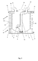
- fig 2 shows the section of a side view of a modular wastewater heat exchanger embodiment according to the invention based on an example of one-drum realisation
- fig 3 shows the section of a side view of a modular wastewater heat exchanger alternative embodiment according to the invention based on an example of two-drum realisation has been depicted.
- a modular heat exchanger according to the embodiment of the present invention, which comprises a double layer drum 4 formed from exterior wall 1, internal wall 2, and horizontal finned tubes 3 located in-between these walls, base 5 fixed to the lower part of the wall, a hollow basis 6, wastewater pump 8 set on the hollow basis and equipped with a float 7, compression ducts 9, the lower edge 10 of which is connected to wastewater pump 8, and the upper edge 11 of which is connected to wastewater output part 12, non-return valve 13 connected into compression duct, lid 16 of the maintenance trapdoor fixed to the upper end of the drum 4 wall, wastewater input part 15, and of wastewater output part 12, cooling liquid input 17 and output 18, wastewater spillway point 19, cooling ducts 20. Cooling liquid is directed between the exterior 1 and internal wall 2 of the double layer wall of the drum and finned tubes 3. Hollow basis 6 is attached to the drum in a way that between basis 6 and base 5 there is an empty space 21.
- Cooling ducts 20 are installed spirally on the internal wall 2 of the drum 4. Cooling liquid is conducted into the cooling ducts 20 through a special input 17. The contour of the cooling ducts 20 is connected with the primary circle of the heat pump following water/water type.
- a cooling mantle for cooling the wastewater is formed from drum 4 double layer wall and cooling ducts 20. With the help of the heat pump and the cooling mantle the wastewater will be cooled to the desired temperature. When the necessary temperature is achieved, the cooled wastewater will be pumped with the help of a wastewater pump 8 through the compression ducts 9 and wastewater output part 12 into the wastewater system of the settlement. The stored heat will be conducted with the help of a heat pump back to the building's heating system.
- Interior modular wastewater heat exchanger is covered with thermal insulation materials in order to avoid heat bleedings.
- the lid 16 of the wastewater heat exchanger is provided with maintenance trapdoor 14.
- wastewater spillway point 19 has been added to the upper part of drum 4, which would lead wastewater out of the building, until the emergency situation is solved.
- the basis 6 of wastewater heat exchanger is made hollow, which reduces the amount of sediments and prolongs maintenance intervals.
- wastewater heat exchanger wastewater is conducted to the upper layer by cooling wastewater in the warmest zone, thus guaranteeing the mixing of temperatures inside wastewater heat exchanger.
- the cooled liquid will sink into the lower part and press warmer upwards.
- a wastewater heat exchanger fabricated following such realisation model is meant for example for mounting into the ground on a wastewater output.
- the internal walls of the wastewater heat exchanger are made up from more than one double layered wall cylinder drums 4.
- the modular wastewater heat exchanger showed in figures fig 1 and fig 2 , is formed from the lower drum 4a and upper drum 4b.
- the upper drum 4b is placed onto the lower drum 4a, and the lower part 22 of the upper drum 4b is fixed to the upper part 23 of the lower drum 4a.
- Base 5 is fixed to the lower edge of the lower drum 4a.
- Hollow basis 6 is fixed to the lower part of the lower drum 4a in a way that there is an empty space 21 between basis 6 and base 5.
- the lid 16 of the maintenance trapdoor 14, wastewater input part 15, and of wastewater output part 12 is fixed to the upper edge of the wall of the upper drum 4b.
- a wastewater pump 8 supplied with a float 7 is placed onto the hollow basis 6, and is connected to the lower edge 10 of compression ducts 9.
- the upper edge 11 of compression ducts 9 is connected to wastewater output part 12.
- a non-return valve 13 Prior to the connection with wastewater output part 12 a non-return valve 13 is connected between wastewater output part 12 and the lower edge 10 of compression ducts 9.
- Cooling liquid input 17 is attached to the lower part of the wall of the lower drum 4a, and cooling liquid output 18 is attached to upper part of the wall of the upper drum 4b.
- Wastewater spillway point 19 is attached to upper part of the wall of the upper drum 4b.
- one or several drums are additionally added between the lower drum 4a and upper drum 4b, in order to connect modular wastewater heat exchanger to larger wastewater systems.
- the cooling mantle has been magnified, and the compression ducts 9 have been lengthened correspondingly.
Landscapes
- Engineering & Computer Science (AREA)
- Physics & Mathematics (AREA)
- Thermal Sciences (AREA)
- Mechanical Engineering (AREA)
- General Engineering & Computer Science (AREA)
- Heat-Exchange Devices With Radiators And Conduit Assemblies (AREA)
Applications Claiming Priority (1)
| Application Number | Priority Date | Filing Date | Title |
|---|---|---|---|
| EEU201000154U EE01075U1 (et) | 2010-12-07 | 2010-12-07 | Reoveesoojusvaheti |
Publications (1)
| Publication Number | Publication Date |
|---|---|
| EP2463609A2 true EP2463609A2 (fr) | 2012-06-13 |
Family
ID=44905451
Family Applications (1)
| Application Number | Title | Priority Date | Filing Date |
|---|---|---|---|
| EP11183802A Withdrawn EP2463609A2 (fr) | 2010-12-07 | 2011-10-04 | Échangeur de chaleur modulaire des eaux usées |
Country Status (2)
| Country | Link |
|---|---|
| EP (1) | EP2463609A2 (fr) |
| EE (1) | EE01075U1 (fr) |
Cited By (3)
| Publication number | Priority date | Publication date | Assignee | Title |
|---|---|---|---|---|
| CN103438732A (zh) * | 2013-08-30 | 2013-12-11 | 北京金房暖通节能技术股份有限公司 | 一种带消音功能的烟囱式烟气余热回收装置及其制造方法 |
| CN106225516A (zh) * | 2016-08-29 | 2016-12-14 | 中山市汉功电器科技有限公司 | 一种清洗保洁方便的废水余热利用装置 |
| WO2017211993A1 (fr) * | 2016-06-08 | 2017-12-14 | Biofluides | Système de récupération de chaleur des eaux usées amélioré |
Citations (3)
| Publication number | Priority date | Publication date | Assignee | Title |
|---|---|---|---|---|
| US5736059A (en) | 1993-03-05 | 1998-04-07 | Mackelvie; Winston R. | Waste water heat recovery system |
| JP2006112671A (ja) | 2004-10-13 | 2006-04-27 | Hitachi Engineering & Services Co Ltd | 渦巻き型温排水熱交換器 |
| WO2009133018A1 (fr) | 2008-04-30 | 2009-11-05 | Huber Se | Échangeur thermique pour eaux usées |
-
2010
- 2010-12-07 EE EEU201000154U patent/EE01075U1/xx not_active IP Right Cessation
-
2011
- 2011-10-04 EP EP11183802A patent/EP2463609A2/fr not_active Withdrawn
Patent Citations (3)
| Publication number | Priority date | Publication date | Assignee | Title |
|---|---|---|---|---|
| US5736059A (en) | 1993-03-05 | 1998-04-07 | Mackelvie; Winston R. | Waste water heat recovery system |
| JP2006112671A (ja) | 2004-10-13 | 2006-04-27 | Hitachi Engineering & Services Co Ltd | 渦巻き型温排水熱交換器 |
| WO2009133018A1 (fr) | 2008-04-30 | 2009-11-05 | Huber Se | Échangeur thermique pour eaux usées |
Cited By (5)
| Publication number | Priority date | Publication date | Assignee | Title |
|---|---|---|---|---|
| CN103438732A (zh) * | 2013-08-30 | 2013-12-11 | 北京金房暖通节能技术股份有限公司 | 一种带消音功能的烟囱式烟气余热回收装置及其制造方法 |
| WO2017211993A1 (fr) * | 2016-06-08 | 2017-12-14 | Biofluides | Système de récupération de chaleur des eaux usées amélioré |
| FR3052540A1 (fr) * | 2016-06-08 | 2017-12-15 | Biofluides | Systeme de recuperation de chaleur des eaux usees ameliore |
| CN106225516A (zh) * | 2016-08-29 | 2016-12-14 | 中山市汉功电器科技有限公司 | 一种清洗保洁方便的废水余热利用装置 |
| CN106225516B (zh) * | 2016-08-29 | 2019-04-19 | 中山市汉功电器科技有限公司 | 一种清洗保洁方便的废水余热利用装置 |
Also Published As
| Publication number | Publication date |
|---|---|
| EE01075U1 (et) | 2012-01-16 |
Similar Documents
| Publication | Publication Date | Title |
|---|---|---|
| US11649615B2 (en) | Lifeline system for compact house | |
| CA2903527C (fr) | Appareil et methode de recuperation de la chaleur | |
| AU2011315156B2 (en) | Heat recovery system, its heat recovery process and use | |
| US20110226341A1 (en) | Device and method for reusing greywater | |
| US11768039B2 (en) | Recovery system and method for recovery of thermal energy from waste water | |
| CA3013029A1 (fr) | Appareil pour transfert de chaleur supplementaire pour systemes geothermiques | |
| Niewitecka | Possibilities of heat energy recovery from greywater systems | |
| EP2463609A2 (fr) | Échangeur de chaleur modulaire des eaux usées | |
| RU2460863C2 (ru) | Мобильный солнечный дом | |
| DK178002B1 (da) | Varmeveksler - for genvinding af restvarme i spildevand fra brusebad | |
| EP3022495B1 (fr) | Système de refroidissement de bâtiments et de chauffage faisant appel à une énergie thermique recyclée provenant d'un bassin de décantation | |
| US20170045237A1 (en) | Tank for energy recovery | |
| JP5360446B1 (ja) | 鉄筋コンクリートスラブ内における雨水貯留構造 | |
| CN102927836A (zh) | 一种回收余热的节能热交换器 | |
| GB2440151A (en) | An arrangement for recovering heat energy from waste water | |
| JP2012528292A (ja) | 廃水からの熱回収 | |
| DE2917987A1 (de) | Waermerueckgewinnung aus haushaltsabwaesser mittels waermepumpe | |
| EP4438958A1 (fr) | Système et procédé pour fournir un chauffage d'eau chaude et/ou d'espace domestique à l'intérieur d'un bâtiment, et couvercle amovible d'un récipient de stockage | |
| CZ2019111A3 (cs) | Způsob využití tepelné energie komunálních odpadních vod z obytných domů a kondominií a zařízení k provádění způsobu | |
| WO2014162293A1 (fr) | Système de traitement de l'eau pour bâtiments hors réseau | |
| CN204301187U (zh) | 生活用水环保节能装置 | |
| CN208968088U (zh) | 一种浴室用地源-污水源热泵洗浴废水能量梯级利用系统 | |
| CN202145060U (zh) | 利用塑料管网对低品位能源进行采集、提取与转换的装置 | |
| KR101073629B1 (ko) | 폐열 교환기 | |
| JPH0618088A (ja) | 家庭用温排水の熱回収装置及び家庭用給湯装置 |
Legal Events
| Date | Code | Title | Description |
|---|---|---|---|
| PUAI | Public reference made under article 153(3) epc to a published international application that has entered the european phase |
Free format text: ORIGINAL CODE: 0009012 |
|
| AK | Designated contracting states |
Kind code of ref document: A2 Designated state(s): AL AT BE BG CH CY CZ DE DK EE ES FI FR GB GR HR HU IE IS IT LI LT LU LV MC MK MT NL NO PL PT RO RS SE SI SK SM TR |
|
| AX | Request for extension of the european patent |
Extension state: BA ME |
|
| RAP1 | Party data changed (applicant data changed or rights of an application transferred) |
Owner name: ONE ENERGY OUE |
|
| RIN1 | Information on inventor provided before grant (corrected) |
Inventor name: RESEV, MEELIS |
|
| STAA | Information on the status of an ep patent application or granted ep patent |
Free format text: STATUS: THE APPLICATION IS DEEMED TO BE WITHDRAWN |
|
| 18D | Application deemed to be withdrawn |
Effective date: 20150501 |