EP2463611A1 - Wärmetauscher vom Typ Flüssigkeit/Gas, insbesondere für Klimaanlagengeräte in einem Kraffahrzeug - Google Patents
Wärmetauscher vom Typ Flüssigkeit/Gas, insbesondere für Klimaanlagengeräte in einem Kraffahrzeug Download PDFInfo
- Publication number
- EP2463611A1 EP2463611A1 EP11192054A EP11192054A EP2463611A1 EP 2463611 A1 EP2463611 A1 EP 2463611A1 EP 11192054 A EP11192054 A EP 11192054A EP 11192054 A EP11192054 A EP 11192054A EP 2463611 A1 EP2463611 A1 EP 2463611A1
- Authority
- EP
- European Patent Office
- Prior art keywords
- fluid
- blade head
- tube
- circulation
- heat exchanger
- Prior art date
- Legal status (The legal status is an assumption and is not a legal conclusion. Google has not performed a legal analysis and makes no representation as to the accuracy of the status listed.)
- Withdrawn
Links
- 238000004378 air conditioning Methods 0.000 title description 3
- 239000012530 fluid Substances 0.000 claims abstract description 137
- 239000000463 material Substances 0.000 claims abstract description 20
- 125000006850 spacer group Chemical group 0.000 claims abstract description 15
- 238000000034 method Methods 0.000 claims abstract description 7
- 239000003507 refrigerant Substances 0.000 description 5
- XLYOFNOQVPJJNP-UHFFFAOYSA-N water Substances O XLYOFNOQVPJJNP-UHFFFAOYSA-N 0.000 description 4
- 230000002528 anti-freeze Effects 0.000 description 3
- 239000002826 coolant Substances 0.000 description 3
- 230000000694 effects Effects 0.000 description 3
- 239000007788 liquid Substances 0.000 description 3
- CURLTUGMZLYLDI-UHFFFAOYSA-N Carbon dioxide Chemical compound O=C=O CURLTUGMZLYLDI-UHFFFAOYSA-N 0.000 description 2
- LYCAIKOWRPUZTN-UHFFFAOYSA-N Ethylene glycol Chemical compound OCCO LYCAIKOWRPUZTN-UHFFFAOYSA-N 0.000 description 2
- 230000000712 assembly Effects 0.000 description 2
- 238000000429 assembly Methods 0.000 description 2
- 238000005452 bending Methods 0.000 description 2
- 235000021183 entrée Nutrition 0.000 description 2
- 108010053481 Antifreeze Proteins Proteins 0.000 description 1
- 239000003570 air Substances 0.000 description 1
- 239000012080 ambient air Substances 0.000 description 1
- 230000000903 blocking effect Effects 0.000 description 1
- 229910002092 carbon dioxide Inorganic materials 0.000 description 1
- 239000001569 carbon dioxide Substances 0.000 description 1
- 230000005465 channeling Effects 0.000 description 1
- 238000004891 communication Methods 0.000 description 1
- 239000000110 cooling liquid Substances 0.000 description 1
- -1 for example Substances 0.000 description 1
- WGCNASOHLSPBMP-UHFFFAOYSA-N hydroxyacetaldehyde Natural products OCC=O WGCNASOHLSPBMP-UHFFFAOYSA-N 0.000 description 1
- 239000000203 mixture Substances 0.000 description 1
- 230000001737 promoting effect Effects 0.000 description 1
- 230000000717 retained effect Effects 0.000 description 1
Images


Classifications
-
- F—MECHANICAL ENGINEERING; LIGHTING; HEATING; WEAPONS; BLASTING
- F28—HEAT EXCHANGE IN GENERAL
- F28F—DETAILS OF HEAT-EXCHANGE AND HEAT-TRANSFER APPARATUS, OF GENERAL APPLICATION
- F28F9/00—Casings; Header boxes; Auxiliary supports for elements; Auxiliary members within casings
- F28F9/02—Header boxes; End plates
- F28F9/0219—Arrangements for sealing end plates into casing or header box; Header box sub-elements
- F28F9/0221—Header boxes or end plates formed by stacked elements
-
- F—MECHANICAL ENGINEERING; LIGHTING; HEATING; WEAPONS; BLASTING
- F28—HEAT EXCHANGE IN GENERAL
- F28D—HEAT-EXCHANGE APPARATUS, NOT PROVIDED FOR IN ANOTHER SUBCLASS, IN WHICH THE HEAT-EXCHANGE MEDIA DO NOT COME INTO DIRECT CONTACT
- F28D1/00—Heat-exchange apparatus having stationary conduit assemblies for one heat-exchange medium only, the media being in contact with different sides of the conduit wall, in which the other heat-exchange medium is a large body of fluid, e.g. domestic or motor car radiators
- F28D1/02—Heat-exchange apparatus having stationary conduit assemblies for one heat-exchange medium only, the media being in contact with different sides of the conduit wall, in which the other heat-exchange medium is a large body of fluid, e.g. domestic or motor car radiators with heat-exchange conduits immersed in the body of fluid
- F28D1/04—Heat-exchange apparatus having stationary conduit assemblies for one heat-exchange medium only, the media being in contact with different sides of the conduit wall, in which the other heat-exchange medium is a large body of fluid, e.g. domestic or motor car radiators with heat-exchange conduits immersed in the body of fluid with tubular conduits
- F28D1/053—Heat-exchange apparatus having stationary conduit assemblies for one heat-exchange medium only, the media being in contact with different sides of the conduit wall, in which the other heat-exchange medium is a large body of fluid, e.g. domestic or motor car radiators with heat-exchange conduits immersed in the body of fluid with tubular conduits the conduits being straight
- F28D1/0535—Heat-exchange apparatus having stationary conduit assemblies for one heat-exchange medium only, the media being in contact with different sides of the conduit wall, in which the other heat-exchange medium is a large body of fluid, e.g. domestic or motor car radiators with heat-exchange conduits immersed in the body of fluid with tubular conduits the conduits being straight the conduits having a non-circular cross-section
- F28D1/05358—Assemblies of conduits connected side by side or with individual headers, e.g. section type radiators
-
- F—MECHANICAL ENGINEERING; LIGHTING; HEATING; WEAPONS; BLASTING
- F28—HEAT EXCHANGE IN GENERAL
- F28D—HEAT-EXCHANGE APPARATUS, NOT PROVIDED FOR IN ANOTHER SUBCLASS, IN WHICH THE HEAT-EXCHANGE MEDIA DO NOT COME INTO DIRECT CONTACT
- F28D7/00—Heat-exchange apparatus having stationary tubular conduit assemblies for both heat-exchange media, the media being in contact with different sides of a conduit wall
- F28D7/16—Heat-exchange apparatus having stationary tubular conduit assemblies for both heat-exchange media, the media being in contact with different sides of a conduit wall the conduits being arranged in parallel spaced relation
- F28D7/1684—Heat-exchange apparatus having stationary tubular conduit assemblies for both heat-exchange media, the media being in contact with different sides of a conduit wall the conduits being arranged in parallel spaced relation the conduits having a non-circular cross-section
Definitions
- the invention relates to heat exchangers of the liquid / gas type, especially for air conditioning equipment of a motor vehicle.
- heat exchangers for air conditioning circuits using a refrigerant such as freon-based fluids, carbon dioxide (CO 2 ) and / or the known fluid under the name of 1234YF.
- Such a circuit essentially comprises a compressor, a condenser or gas cooler, an expander and an evaporator.
- the condenser or gas cooler is arranged to condense and / or cool a first refrigerant fluid by heat exchange with a second fluid such as, for example, ambient air (air / gas type heat exchanger) or a cooling liquid, for example an anti-freeze mixture of water and glycol (liquid / gas type heat exchanger).
- the invention relates more precisely to the heat exchangers of the liquid / gas type, also called “water / gas exchanger” or “Water / Gas Heat exchanger (WGC)", equipping such circuits.
- heat exchangers comprising a refrigerant collector box formed of heads of blades superimposed on each other. Mounted with tubes for circulating the first fluid, they make it possible to create circulation channels for the second fluid between the tubes.
- the existing blade heads are not modifiable or adaptable to obtain a given height between two circulation tubes of the first fluid.
- the object of the invention is to overcome these drawbacks by proposing a heat exchanger blade head, said heat exchanger permitting an exchange between a first fluid and a second fluid, in particular a heat exchanger for an automobile, said head blade being adapted to receive a flow tube of the first fluid and to be superimposed on an identical blade head by defining a spacer between the tubes inserted in said blade heads so as to obtain a space for the circulation of the second fluid, the blade head being characterized in that it comprises several flaps obtained by folding on itself a sheet of material so that at least a first flap is adapted to receive a circulation tube of the first fluid and that less a second flap is able to define at least partly the spacer between two circulation tubes of the first fluid.
- the first flap is formed by a material thickness of the sheet of material and the second flap is formed by another material thickness of the sheet of material.
- the sheet of material is, for example, of constant thickness so that the two flaps have the same thickness.
- An advantage of the folded blade head according to the invention is to be able to reduce the number of parts by using a single piece to define the flow of the two fluids.
- Another advantage of the blade head according to the invention is that, since the thickness conferred by the folding of the blade head determines the height of the tube, this tube height can thus be adapted, configured or modified to a certain extent. value given according to the thickness of the shutters and the number of folding.
- the thickness of the folded blade head corresponds to the superposition of the first and second shutters.
- the blade head comprises at least one circulation orifice of the first fluid and / or a circulation orifice of the second fluid. This has the advantage of allowing the circulation of respectively first and second fluids by different paths.
- a part of the first component comprises a stop capable of allowing the positioning of the circulation tube of the first fluid. This has the advantage of limiting the stroke of the tube relative to the blade head so that the tube is nested with the blade head.
- a portion of the first flap has a trapezoidal shape adapted to guide the first fluid between the tube and at least one flow orifice of the first fluid.
- This has the advantage of allowing the channeling of the first fluid towards the orifices or circulation of the first fluid, for example provided in the second flap, given the frustoconical or funnel-shaped sides of the trapezoidal section formed in the first flap .
- This also has the advantage of improving the flow efficiency of the first fluid at the outlet of the tube since the tube can extend over the entire width of the large base of the trapezoidal section.
- the first and / or second flap comprises at least one extension capable of retaining a wall of the heat exchanger. This has the advantage of allowing the positioning or blocking of the side walls of the heat exchanger, thus avoiding the need to add an additional piece or a hanging walls to perform this function.
- the sheet of material comprises at least one line or at least one folding hole adapted to allow said folding. This has the advantage of facilitating the folding of the sheet of material to obtain the blade head.
- the blade head comprises at least one secondary orifice adapted to the circulation of a fluid, especially the first fluid.
- the blade head comprises at least one support for supporting the flow tube of the first fluid. This has the advantage of promoting the nesting of the tube with the blade head. Said support is provided, for example, at the second component.
- the invention also relates to an assembly formed by at least one blade head as defined above and a flow tube of the first fluid, the first flap of said blade head receiving said flow tube of the first fluid.
- the assembly may comprise a tube and a said blade head at each end of the tube.
- the circulation tube of the first fluid has a thickness identical to the material thickness of the first component.
- the thickness of the flow tube of the first fluid is then identical to the thickness of the second flap defining the height between two tubes. This has the advantage of the ease of folding of the blade head since it is folded once. If it is desired to adjust the height of the space between two tubes, more than two parts can be provided by folding the sheet of material several times.
- the flow tube of the first fluid closes the contour of the communication ports of the blade head so that the conduits of the first and second fluid are distinct. In this way, the passage sections are also optimized.
- the invention also relates to a heat exchanger between a first fluid and a second fluid, in particular a heat exchanger for an automobile.
- the heat exchanger comprises at least one assembly formed of a blade head and a tube as defined above.
- the heat exchanger further comprises two side walls, a first cover and a second cover opposite to the first cover, forming a circulation housing of the second fluid.
- one of the covers includes an inlet flange of the first or second fluid in the heat exchanger and an outlet flange of the first or second fluid of the heat exchanger. This has the advantage of facilitating the connection of the exchanger to the circuit.
- the invention also relates to a heat exchanger collector box.
- the manifold includes a plurality of blade heads as defined above stacked on top of one another.
- the invention also relates to a method for obtaining a heat exchanger blade head between a first fluid and a second fluid, in particular a heat exchanger for an automobile, the blade head being able to receive a tube of circulating the first fluid and being superimposed on an identical blade head by defining a spacer between the tubes inserted in said blade heads so as to obtain a space for the circulation of the second fluid.
- said method comprises at least one step of folding the blade head on itself and in at least two flaps so that at least one first flap is adapted to receive a circulation tube of the first fluid and at least one second flap is able to define at least partly the spacer between two circulation tubes of the first fluid.
- the blade head 10 is a heat exchanger blade head between a first fluid and a second fluid, in particular a heat exchanger for an automobile.
- the figure 1 describes the blade head 10 before folding.
- the blade head 10 may comprise a line or a bending hole 19 adapted to allow the folding configuration of the blade head 10.
- a bending line or a boring hole adapted to allow the folding configuration of the blade head 10. Folding can be performed respectively on or in the blade head 10 before folding so as to facilitate later the folding of the blade head 10.
- the figure 2 discloses a blade head 10 configured by at least one folding according to the invention. On the Figure 2 in a preferred embodiment of the invention, the blade head has been folded once.
- the blade head is adapted to receive a tube 20 for circulating the first fluid (with reference to the Figure 3 ) and to be superimposed on an identical blade head (with reference to Figures 4 and following) by defining a spacer between the tubes 20 inserted in said blade heads 10 so as to obtain a space allowing the circulation of the second fluid.
- the head of blade 10 comprises several flaps obtained by folding on itself a sheet of material so that at least one first flap 6 is adapted to receive a tube 20 for circulation of the first fluid and at least one second flap 8 is adapted to define at least partly the spacer between two tubes 20 of circulation of the first fluid.
- the sheet of material has been folded once to obtain the blade head 10.
- the number of folding the sheet of material used can be multiple, thus allowing to adjust the height of the circulation space of the second fluid between two flow tube of the first fluid.
- the height of the circulation space of the second fluid between two circulation tube of the first fluid needs to be for example twice as thick as the tube and if the blade head is cut in a sheet of thickness identical to the thickness of a flow tube of the first fluid, then a second folding of the sheet of material forming the blade head can be operated to obtain the corresponding height.
- This has the effect of increasing the passage section for the circulation of the second fluid between two circulation tubes of the first fluid while having used to make a single folded blade head.
- the blade head 10 comprises in particular a main orifice 17 adapted to the circulation of a fluid, here the first fluid.
- the blade head 10 according to the invention may also comprise at least one orifice 15 for the passage of the second fluid.
- the blade head 10 comprises two orifices 15 on either side of the blade head 10.
- the blade head 10 may comprise at least one circulation orifice 17 of the first fluid and a circulation orifice 15 of the second fluid.
- the first and second flaps define two orifices 15 and the second flap comprises the orifice 17.
- the second flap 8 comprises at least one abutment 13 (for example a wedge) capable of allowing the positioning of the tube 20 for circulating the first fluid in the longitudinal axis. of the circulation tube 20 of the first fluid.
- abutment 13 for example a wedge
- a portion of the first flap 6 has a trapezoidal shape adapted to guide the first fluid between the tube 20 at least one orifice 17 for circulation of the first fluid.
- the large base of the trapezoidal section corresponds to the width of the tube 20 so that the first fluid flows over the entire width of the tube 20.
- the blade head 10, in particular the second flap may comprise a plurality of orifices 17, 18 for the circulation of the first fluid.
- the first or the second flap may comprise at least one extension 14 capable of retaining a wall 38 (with reference to FIG. Figure 4 ) of a heat exchanger 30 (with reference to Figures 4 to 6 ).
- the blade head 10, and more particularly the second flap 8 of the blade head 10 comprises at least one support (11, 12) for supporting a tube 20 of circulation of the first fluid. This has the effect of allowing axial and / or lateral support to the tube 20 for circulating the first fluid.
- the invention also relates to an assembly formed by at least one heat exchanger blade head 30 between a first fluid and a second fluid as defined above and a tube 20 for circulating the first fluid, the first component 6 of said first fluid.
- blade head 10 receiving said tube 20 for circulating the first fluid.
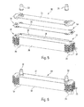
- FIG 3 described, in an illustrative embodiment according to the present invention, an assembly formed by two blade heads 10 and a tube 20 for circulating the first fluid, the first flap 6 of each of the blade heads 10 receiving the circulation tube 20 of the first fluid.
- the contour of the orifice 15 of the blade head 10 is open.
- the tube 20 for circulating the first fluid closes the contour of the orifice 15 of the head This has the effect of allowing the flow of the first fluid to be separated by the orifice 17 (or the orifices 17, 18) and the second fluid through the orifice 15.
- the thickness of the folded blade head 10 corresponds to the superposition of the first shutter 6 and the second shutter 8 and the circulation tube 20 of the first fluid has a thickness. identical to the material thickness of the first flap 6.
- the thickness of the tube 20 for circulating the first fluid is also identical to the thickness of the second flap 8 defining the height between two tubes 20 of the heat exchanger .
- the invention also relates to a heat exchanger 30 between a first fluid and a second fluid, in particular a heat exchanger for an automobile.
- the heat exchanger 30 comprises at least one assembly as described above.
- formed sets of blade heads 10 and tubes 20 for circulating the first fluid are stacked on each other.
- the shape, in particular outer, of the blade heads 10 ensures a good alignment between the parts.
- the last blade head 10 can be closed by a sheet cut into the corresponding format.
- the heat exchanger further comprises two side walls 38, a first cover 31 or 36 and a second cover opposite to the first cover respectively 36 or 31.
- the cover 36 comprises a flange 34 (or tubing) d inlet of the first fluid in the heat exchanger and an outlet flange 34 of the first fluid of the heat exchanger 30.
- the other 31 of the covers comprises an inlet flange 32 of the second fluid in the heat exchanger 30 and an outlet flange 32 of the second fluid of the heat exchanger 30.
- the bundle of tubes may be closed at the ends by two cheeks or covers 31, 36, one of which is pressed to accommodate the inlet / outlet flanges 32 of the second fluid (for example antifreeze) and the other is able to receive flanges.
- 34 input / output of the first fluid for example refrigerant.
- the other two sides can be closed by two cut sheets forming walls 38.
- the heat exchanger 30 thus obtained can be brazed in one go with the flanges 34 and the flanges 32.
- the first fluid enters the heat exchanger through one of the flanges 34, circulates at the inside of the hollow tubes 20 (for example extruded tubes) and the orifices (17, 18) of the blade heads 10 and then spring through the other flange 34.
- the second fluid enters the collecting box 30 by a flange 32 and then circulates between each pair of tubes 20 via the orifices 15 and then out through the other flange 32.
- the cover 31, 36 may include a mounting hole 35 for securing the exchanger to a support.
- an additional blade head may be added at each manifold end between a lid 31, 36 and the last stacked tube (as shown in FIG. figure 4 ), defining a spacer between said last tube 20 and the cover 31, 36 so as to obtain a space for the circulation of the second fluid.
- the shape of the lid can also be used to define a spacer between the last tube 20 and said cover so as to obtain a space for the circulation of the second fluid.
- the invention also relates to a method for obtaining a heat exchanger blade head between a first fluid and a second fluid, in particular a heat exchanger for an automobile.
- the blade head 10 is adapted to receive a tube 20 for circulating the first fluid and to be superimposed on an identical blade head 10 by defining a spacer between the tubes 20 inserted in said blade heads 10 so as to obtain a space allowing the circulation of the second fluid.
- the method comprises at least one step of folding the blade head 10 on itself and at least two flaps 6, 8 so that at least one first flap 6 is adapted to receive a tube 20 for circulating the first fluid and at least one second flap 8 is able to define at least partly the spacer between two tubes 20 of circulation of the first fluid.
Landscapes
- Engineering & Computer Science (AREA)
- Physics & Mathematics (AREA)
- Thermal Sciences (AREA)
- Mechanical Engineering (AREA)
- General Engineering & Computer Science (AREA)
- Heat-Exchange Devices With Radiators And Conduit Assemblies (AREA)
Applications Claiming Priority (1)
| Application Number | Priority Date | Filing Date | Title |
|---|---|---|---|
| FR1060362A FR2968752B1 (fr) | 2010-12-10 | 2010-12-10 | Echangeurs de chaleur de type liquide/gaz, notamment pour les equipements de climatisation de vehicule automobile |
Publications (1)
| Publication Number | Publication Date |
|---|---|
| EP2463611A1 true EP2463611A1 (de) | 2012-06-13 |
Family
ID=44512293
Family Applications (1)
| Application Number | Title | Priority Date | Filing Date |
|---|---|---|---|
| EP11192054A Withdrawn EP2463611A1 (de) | 2010-12-10 | 2011-12-06 | Wärmetauscher vom Typ Flüssigkeit/Gas, insbesondere für Klimaanlagengeräte in einem Kraffahrzeug |
Country Status (2)
| Country | Link |
|---|---|
| EP (1) | EP2463611A1 (de) |
| FR (1) | FR2968752B1 (de) |
Cited By (3)
| Publication number | Priority date | Publication date | Assignee | Title |
|---|---|---|---|---|
| FR3045802A1 (fr) * | 2015-12-21 | 2017-06-23 | Valeo Systemes Thermiques | Echangeur thermique, notamment pour vehicule automobile |
| WO2017213164A1 (ja) * | 2016-06-10 | 2017-12-14 | サンデンホールディングス株式会社 | 車両用熱交換器 |
| WO2018127642A1 (fr) * | 2017-01-06 | 2018-07-12 | Valeo Systemes Thermiques | Boîte collectrice pour échangeur thermique, notamment pour véhicule automobile, échangeur thermique et procédé de fabrication correspondant |
Citations (6)
| Publication number | Priority date | Publication date | Assignee | Title |
|---|---|---|---|---|
| WO2003056268A1 (fr) * | 2001-12-28 | 2003-07-10 | Valeo Thermique Moteur | Elément de circuit pour échangeur de chaleur, notamment de véhicule automobile et échangeur de chaleur ainsi obtenu |
| FR2852383A1 (fr) * | 2003-03-11 | 2004-09-17 | Valeo Thermique Moteur Sa | Boite collectrice pour echangeur de chaleur a haute pression et echangeur de chaleur comportant cette boite collectrice |
| FR2864215A1 (fr) * | 2003-12-19 | 2005-06-24 | Valeo Climatisation | Element de circuit pour echangeur de chaleur |
| DE102006054460A1 (de) * | 2005-11-17 | 2007-05-24 | Behr Gmbh & Co. Kg | Wärmetauscher |
| EP1903293A2 (de) * | 2006-09-21 | 2008-03-26 | Valeo Systèmes Thermiques | Gas-Wasser-Wärmetauscher, insbesondere für eine Klimaanlage eines Kraftfahrzeugs, bei der eine Kühlflüssigkeit zum Einsatz kommt, die im superkritischen Zustand eingesetzt wird, wie CO2 |
| FR2908871A1 (fr) * | 2006-11-21 | 2008-05-23 | Valeo Systemes Thermiques | Echangeur de chaleur interne pour circuit de fluide refrigerant |
-
2010
- 2010-12-10 FR FR1060362A patent/FR2968752B1/fr not_active Expired - Fee Related
-
2011
- 2011-12-06 EP EP11192054A patent/EP2463611A1/de not_active Withdrawn
Patent Citations (6)
| Publication number | Priority date | Publication date | Assignee | Title |
|---|---|---|---|---|
| WO2003056268A1 (fr) * | 2001-12-28 | 2003-07-10 | Valeo Thermique Moteur | Elément de circuit pour échangeur de chaleur, notamment de véhicule automobile et échangeur de chaleur ainsi obtenu |
| FR2852383A1 (fr) * | 2003-03-11 | 2004-09-17 | Valeo Thermique Moteur Sa | Boite collectrice pour echangeur de chaleur a haute pression et echangeur de chaleur comportant cette boite collectrice |
| FR2864215A1 (fr) * | 2003-12-19 | 2005-06-24 | Valeo Climatisation | Element de circuit pour echangeur de chaleur |
| DE102006054460A1 (de) * | 2005-11-17 | 2007-05-24 | Behr Gmbh & Co. Kg | Wärmetauscher |
| EP1903293A2 (de) * | 2006-09-21 | 2008-03-26 | Valeo Systèmes Thermiques | Gas-Wasser-Wärmetauscher, insbesondere für eine Klimaanlage eines Kraftfahrzeugs, bei der eine Kühlflüssigkeit zum Einsatz kommt, die im superkritischen Zustand eingesetzt wird, wie CO2 |
| FR2908871A1 (fr) * | 2006-11-21 | 2008-05-23 | Valeo Systemes Thermiques | Echangeur de chaleur interne pour circuit de fluide refrigerant |
Cited By (7)
| Publication number | Priority date | Publication date | Assignee | Title |
|---|---|---|---|---|
| FR3045802A1 (fr) * | 2015-12-21 | 2017-06-23 | Valeo Systemes Thermiques | Echangeur thermique, notamment pour vehicule automobile |
| WO2017109345A1 (fr) * | 2015-12-21 | 2017-06-29 | Valeo Systemes Thermiques | Échangeur thermique, notamment pour véhicule automobile |
| WO2017213164A1 (ja) * | 2016-06-10 | 2017-12-14 | サンデンホールディングス株式会社 | 車両用熱交換器 |
| WO2018127642A1 (fr) * | 2017-01-06 | 2018-07-12 | Valeo Systemes Thermiques | Boîte collectrice pour échangeur thermique, notamment pour véhicule automobile, échangeur thermique et procédé de fabrication correspondant |
| FR3061767A1 (fr) * | 2017-01-06 | 2018-07-13 | Valeo Systemes Thermiques | Boite collectrice pour echangeur thermique, notamment pour vehicule automobile, echangeur thermique et procede de fabrication correspondant. |
| CN110366668A (zh) * | 2017-01-06 | 2019-10-22 | 法雷奥热系统公司 | 特别用于机动车辆的热交换器集管箱、热交换器及相应的制造方法 |
| CN110366668B (zh) * | 2017-01-06 | 2021-06-01 | 法雷奥热系统公司 | 特别用于机动车辆的热交换器集管箱、热交换器及相应的制造方法 |
Also Published As
| Publication number | Publication date |
|---|---|
| FR2968752A1 (fr) | 2012-06-15 |
| FR2968752B1 (fr) | 2014-11-21 |
Similar Documents
| Publication | Publication Date | Title |
|---|---|---|
| EP2726804B1 (de) | Wärmetauscher, insbesondere für ein kraftfahrzeug | |
| EP2463612A1 (de) | Antriebskopf eines Wärmetauschers zwischen einem ersten Fluid und einem zweiten Fluid, und Wärmetauscher, insbesondere für Fahrzeuge, der einen solchen Antriebskopf umfasst | |
| EP2912396B1 (de) | Wärmetauscher, insbesondere für ein kraftfahrzeug | |
| EP3289302B1 (de) | Wärmetauscher mit plattenstapel | |
| EP2232030B1 (de) | Ladeluftkühler für fahrzeuge | |
| EP2810009A1 (de) | Kühler für ein fahrzeug, insbesondere ein kraftfahrzeug | |
| FR2968752A1 (fr) | Echangeurs de chaleur de type liquide/gaz, notamment pour les equipements de climatisation de vehicule automobile | |
| EP1762808A1 (de) | Kreislaufelement mit Flachrohren und Wärmetauscher mit demselben | |
| FR2864215A1 (fr) | Element de circuit pour echangeur de chaleur | |
| EP2446208A1 (de) | Wärmetauschereinheit, im besonderen für einen klimaanlagenkondensator | |
| EP3099994B1 (de) | Wärmetauscher für ein kraftfahrzeug | |
| FR2992713A1 (fr) | Faisceau d'echange de chaleur et echangeur de chaleur comprenant ledit faisceau | |
| FR2944591A1 (fr) | Tube de circulation de fluide refrigerant, faisceau d'echange de chaleur et echangeur de chaleur comportant de tels tubes | |
| EP3394545B1 (de) | Wärmetauscher, insbesondere für ein kraftfahrzeug | |
| EP3308096B1 (de) | Wärmetauscher für ein kraftfahrzeug | |
| EP2372288A1 (de) | Wärmetauscher für Klimaanlage mit reduzierten Enden | |
| EP2072936B1 (de) | Einheitlicher Wärmetauscher für Klimakreislauf | |
| FR3060724A1 (fr) | Echangeur thermique, notamment evaporateur, muni d'un dispositif de raccordement pour l'introduction et l'extraction d'un fluide caloporteur. | |
| FR3060107B1 (fr) | Echangeur de chaleur, notamment un refroidisseur d’air de suralimentation de moteur de vehicule automobile | |
| WO2025180698A1 (fr) | Échangeur de chaleur comprenant une pluralité de plaques de circulation de fluide comprenant chacune au moins deux portions distinctes, système de refroidissement et procédé de fabrication | |
| WO2017109350A1 (fr) | Échangeur thermique, notamment pour vehicule automobile | |
| EP3394554B1 (de) | Wärmetauscher, insbesondere für ein kraftfahrzeug | |
| EP1623177A2 (de) | Wärmetauscher, insbesondere für kraftfahrzeuge | |
| WO2019115885A1 (fr) | Échangeur thermique, notamment évaporateur, muni d'un dispositif de raccordement pour l'introduction et l'extraction d'un fluide caloporteur | |
| WO2017109348A1 (fr) | Échangeur thermique, notamment pour véhicule automobile |
Legal Events
| Date | Code | Title | Description |
|---|---|---|---|
| PUAI | Public reference made under article 153(3) epc to a published international application that has entered the european phase |
Free format text: ORIGINAL CODE: 0009012 |
|
| AK | Designated contracting states |
Kind code of ref document: A1 Designated state(s): AL AT BE BG CH CY CZ DE DK EE ES FI FR GB GR HR HU IE IS IT LI LT LU LV MC MK MT NL NO PL PT RO RS SE SI SK SM TR |
|
| AX | Request for extension of the european patent |
Extension state: BA ME |
|
| 17P | Request for examination filed |
Effective date: 20121213 |
|
| 17Q | First examination report despatched |
Effective date: 20161004 |
|
| STAA | Information on the status of an ep patent application or granted ep patent |
Free format text: STATUS: THE APPLICATION IS DEEMED TO BE WITHDRAWN |
|
| 18D | Application deemed to be withdrawn |
Effective date: 20180703 |