EP2464099A2 - Dispositif d'affichage d'images incluant un détecteur de liquide - Google Patents
Dispositif d'affichage d'images incluant un détecteur de liquide Download PDFInfo
- Publication number
- EP2464099A2 EP2464099A2 EP11191464A EP11191464A EP2464099A2 EP 2464099 A2 EP2464099 A2 EP 2464099A2 EP 11191464 A EP11191464 A EP 11191464A EP 11191464 A EP11191464 A EP 11191464A EP 2464099 A2 EP2464099 A2 EP 2464099A2
- Authority
- EP
- European Patent Office
- Prior art keywords
- display
- manipulation
- input
- water
- liquid
- Prior art date
- Legal status (The legal status is an assumption and is not a legal conclusion. Google has not performed a legal analysis and makes no representation as to the accuracy of the status listed.)
- Withdrawn
Links
Images






Classifications
-
- G—PHYSICS
- G06—COMPUTING OR CALCULATING; COUNTING
- G06F—ELECTRIC DIGITAL DATA PROCESSING
- G06F3/00—Input arrangements for transferring data to be processed into a form capable of being handled by the computer; Output arrangements for transferring data from processing unit to output unit, e.g. interface arrangements
- G06F3/01—Input arrangements or combined input and output arrangements for interaction between user and computer
- G06F3/03—Arrangements for converting the position or the displacement of a member into a coded form
- G06F3/041—Digitisers, e.g. for touch screens or touch pads, characterised by the transducing means
- G06F3/0416—Control or interface arrangements specially adapted for digitisers
-
- G—PHYSICS
- G06—COMPUTING OR CALCULATING; COUNTING
- G06F—ELECTRIC DIGITAL DATA PROCESSING
- G06F3/00—Input arrangements for transferring data to be processed into a form capable of being handled by the computer; Output arrangements for transferring data from processing unit to output unit, e.g. interface arrangements
- G06F3/01—Input arrangements or combined input and output arrangements for interaction between user and computer
- G06F3/03—Arrangements for converting the position or the displacement of a member into a coded form
- G06F3/041—Digitisers, e.g. for touch screens or touch pads, characterised by the transducing means
- G06F3/0416—Control or interface arrangements specially adapted for digitisers
- G06F3/0418—Control or interface arrangements specially adapted for digitisers for error correction or compensation, e.g. based on parallax, calibration or alignment
- G06F3/04186—Touch location disambiguation
-
- G—PHYSICS
- G06—COMPUTING OR CALCULATING; COUNTING
- G06F—ELECTRIC DIGITAL DATA PROCESSING
- G06F3/00—Input arrangements for transferring data to be processed into a form capable of being handled by the computer; Output arrangements for transferring data from processing unit to output unit, e.g. interface arrangements
- G06F3/01—Input arrangements or combined input and output arrangements for interaction between user and computer
- G06F3/048—Interaction techniques based on graphical user interfaces [GUI]
- G06F3/0487—Interaction techniques based on graphical user interfaces [GUI] using specific features provided by the input device, e.g. functions controlled by the rotation of a mouse with dual sensing arrangements, or of the nature of the input device, e.g. tap gestures based on pressure sensed by a digitiser
- G06F3/0488—Interaction techniques based on graphical user interfaces [GUI] using specific features provided by the input device, e.g. functions controlled by the rotation of a mouse with dual sensing arrangements, or of the nature of the input device, e.g. tap gestures based on pressure sensed by a digitiser using a touch-screen or digitiser, e.g. input of commands through traced gestures
-
- H—ELECTRICITY
- H04—ELECTRIC COMMUNICATION TECHNIQUE
- H04M—TELEPHONIC COMMUNICATION
- H04M1/00—Substation equipment, e.g. for use by subscribers
- H04M1/02—Constructional features of telephone sets
- H04M1/18—Telephone sets specially adapted for use in ships, mines, or other places exposed to adverse environment
-
- H—ELECTRICITY
- H04—ELECTRIC COMMUNICATION TECHNIQUE
- H04M—TELEPHONIC COMMUNICATION
- H04M1/00—Substation equipment, e.g. for use by subscribers
- H04M1/72—Mobile telephones; Cordless telephones, i.e. devices for establishing wireless links to base stations without route selection
- H04M1/724—User interfaces specially adapted for cordless or mobile telephones
- H04M1/72448—User interfaces specially adapted for cordless or mobile telephones with means for adapting the functionality of the device according to specific conditions
- H04M1/72463—User interfaces specially adapted for cordless or mobile telephones with means for adapting the functionality of the device according to specific conditions to restrict the functionality of the device
- H04M1/724631—User interfaces specially adapted for cordless or mobile telephones with means for adapting the functionality of the device according to specific conditions to restrict the functionality of the device by limiting the access to the user interface, e.g. locking a touch-screen or a keypad
-
- H—ELECTRICITY
- H04—ELECTRIC COMMUNICATION TECHNIQUE
- H04N—PICTORIAL COMMUNICATION, e.g. TELEVISION
- H04N23/00—Cameras or camera modules comprising electronic image sensors; Control thereof
- H04N23/60—Control of cameras or camera modules
- H04N23/61—Control of cameras or camera modules based on recognised objects
-
- H—ELECTRICITY
- H04—ELECTRIC COMMUNICATION TECHNIQUE
- H04N—PICTORIAL COMMUNICATION, e.g. TELEVISION
- H04N23/00—Cameras or camera modules comprising electronic image sensors; Control thereof
- H04N23/60—Control of cameras or camera modules
- H04N23/62—Control of parameters via user interfaces
-
- H—ELECTRICITY
- H04—ELECTRIC COMMUNICATION TECHNIQUE
- H04N—PICTORIAL COMMUNICATION, e.g. TELEVISION
- H04N23/00—Cameras or camera modules comprising electronic image sensors; Control thereof
- H04N23/60—Control of cameras or camera modules
- H04N23/63—Control of cameras or camera modules by using electronic viewfinders
- H04N23/631—Graphical user interfaces [GUI] specially adapted for controlling image capture or setting capture parameters
-
- H—ELECTRICITY
- H04—ELECTRIC COMMUNICATION TECHNIQUE
- H04N—PICTORIAL COMMUNICATION, e.g. TELEVISION
- H04N23/00—Cameras or camera modules comprising electronic image sensors; Control thereof
- H04N23/60—Control of cameras or camera modules
- H04N23/63—Control of cameras or camera modules by using electronic viewfinders
- H04N23/633—Control of cameras or camera modules by using electronic viewfinders for displaying additional information relating to control or operation of the camera
- H04N23/634—Warning indications
-
- H—ELECTRICITY
- H04—ELECTRIC COMMUNICATION TECHNIQUE
- H04N—PICTORIAL COMMUNICATION, e.g. TELEVISION
- H04N23/00—Cameras or camera modules comprising electronic image sensors; Control thereof
- H04N23/60—Control of cameras or camera modules
- H04N23/63—Control of cameras or camera modules by using electronic viewfinders
- H04N23/633—Control of cameras or camera modules by using electronic viewfinders for displaying additional information relating to control or operation of the camera
- H04N23/635—Region indicators; Field of view indicators
-
- H—ELECTRICITY
- H04—ELECTRIC COMMUNICATION TECHNIQUE
- H04N—PICTORIAL COMMUNICATION, e.g. TELEVISION
- H04N2201/00—Indexing scheme relating to scanning, transmission or reproduction of documents or the like, and to details thereof
- H04N2201/0077—Types of the still picture apparatus
- H04N2201/0084—Digital still camera
-
- H—ELECTRICITY
- H04—ELECTRIC COMMUNICATION TECHNIQUE
- H04N—PICTORIAL COMMUNICATION, e.g. TELEVISION
- H04N23/00—Cameras or camera modules comprising electronic image sensors; Control thereof
- H04N23/60—Control of cameras or camera modules
- H04N23/67—Focus control based on electronic image sensor signals
- H04N23/675—Focus control based on electronic image sensor signals comprising setting of focusing regions
Definitions
- the present disclosure relates to an electronic apparatus.
- an electronic apparatus that displays a manipulation image used to perform an manipulation input on a display surface (for example, touch panel) and receives the manipulation input based on a detection state of an object brought close to or into contact with the display surface.
- a display surface for example, touch panel
- FIG. 7 of Japanese Patent Application Laid-Open No. 2009-212980 discloses an imaging apparatus, in which an assignment button used to assign a dog or a cat as a target of automatic photographing is displayed on the touch panel and the manipulation input is received based on a manipulation to press down the assignment button.
- an imaging operation is performed on a beach with a waterproof imaging apparatus including an electrostatic type (capacitance type) touch panel that detects the contact or proximity of an object (such as a finger of a person) having conductivity based on a change in capacitance.
- an electrostatic type capactance type
- the imaging apparatus is splashed with water from the sea and the splash adheres to the imaging apparatus during the imaging operation. Therefore, for example, it is also conceivable that the splash adheres to the touch panel of the imaging apparatus.
- the water has conductivity
- the water is detected as the contact of an object having conductivity and the manipulation input is performed based on the detection state.
- the manipulation input is performed based on the detection state of the water adhesion and an undesired imaging operation (malfunction) is performed based on the manipulation input. Therefore, when the water adheres to the touch panel during the use of the electronic apparatus, it is necessary to prevent the malfunction caused by the water adhesion.
- an electronic apparatus including a display configured to display an image, a liquid detection unit configured to detect liquid on a surface of the display, and a display control unit configured to change a display mode of the display based on the detection of liquid on the surface of the display by the liquid detection unit.
- a method including displaying an image on a display, detecting liquid on a surface of the display, and changing a display mode of the display based on the detection of liquid on the surface of the display.
- a non-transitory computer readable medium encoded with computer readable instructions which, when loaded on a processor, cause the processor to execute a method including displaying an image on a display, detecting liquid on a surface of the display, and changing a display mode of the display based on the detection of liquid on the surface of the display.
- Some embodiments of the present disclosure relate to an electronic apparatus that causes an input/output unit to display a manipulation image to receive a manipulation input, a method for controlling the electronic apparatus, and a program that causes a computer to execute the method.
- the effect of preventing the malfunction at the time of the water adhesion is obtained.
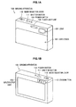
- FIGS. 1A and 1B are perspective views illustrating an example of a configuration of an imaging apparatus 100 according to a first embodiment of the present disclosure.
- FIG. 1A illustrates an appearance of a front surface (that is, a surface in which a lens 121 directed at a subject is provided) side of the imaging apparatus 100.
- FIG. 1B illustrates an appearance of a rear surface (that is, a surface of an input/output unit 150 directed toward the user) side of the imaging apparatus 100.
- the imaging apparatus 100 includes a lens cover 101, a flash lamp unit 102, a shutter button 111, a mode selector lever 112, a zoom button 113, a power switch 114, a lens 121, and the input/output unit 150.
- the imaging apparatus 100 is implemented by a digital still camera and a digital video camera (such as a camera built-in recorder), to which a waterproof treatment is performed using a waterproof member (not illustrated) that prevents liquid from entering the apparatus.
- a waterproof member not illustrated
- the imaging apparatus 100 is an example of the electronic apparatus described in claims.
- Each device provided on the front surface side of the imaging apparatus 100 is covered with the lens cover 101.
- the lens cover 101 can vertically be moved, and the lens 121 and the flash lamp unit 102 can be covered with the lens cover 101 in a non-imaging operation state by moving the lens cover 101 upward in the vertical direction.
- the flash lamp unit 102 is a light emitting device that emits light to the subject.
- the flash lamp unit 102 is used when the imaging operation is performed with the imaging apparatus 100 in an environment, such as nighttime and a room inside, in which sufficient luminance is not expected.
- the shutter button 111 is a manipulation member that is pressed down by the user when the captured image (image data) that is generated by capturing the subject is recorded as a content (still image content). For example, in the case where a still image capturing mode is set to record a still image, a focus is controlled to perform auto focus when the shutter button 111 is pressed halfway. When the shutter button 111 is fully pressed, the focus control is performed, and the captured image (image data) generated by an imaging unit 120 ( FIG. 2 ) at this full press is recorded as the content (still image content) in a recording medium 140 ( FIG. 2 ).
- the mode selector lever 112 is a manipulation member that is used in performing a functional-mode switching manipulation. For example, one of an imaging mode in which the generated image data is recorded as an image content and a reproducing mode in which the recorded image content is reproduced is set as the functional mode.
- the mode selector lever 112 is a mode switching manipulation member that is used in performing the functional-mode switching manipulation.
- one of the imaging modes in which the generated captured image (image data) is recorded as the content (still image content or moving image content) and the reproducing mode in which the stored content is reproduced is set as the functional mode.
- One of a still image capturing mode in which the generated captured image is recorded as the still image content (still image file) and a moving image capturing mode in which the generated captured image is recorded as the moving image content (moving image file) can be set as the imaging mode.
- the zoom button 113 is a manipulation member that is used in performing a zoom manipulation (manipulation to adjust zoom magnification).
- a W (wide) button wide-side button
- a T (tele) button tele-side button
- the power switch 114 is a manipulation member that is used in turning on and off the power of the imaging apparatus 100.
- the lens 121 (including a zoom lens and a focus lens) collects light from the subject.
- the input/output unit 150 displays various images and receives a manipulation input from the user based on a detection state of an object that is brought close to or into contact with a display surface.
- the input/output unit 150 is also called a touch screen or a touch panel.
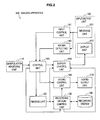
- FIG. 2 is a block diagram illustrating a functional configuration of the imaging apparatus 100 according to the first embodiment of the present disclosure.
- the imaging apparatus 100 includes a manipulation receiving unit 110, the imaging unit 120, a recording medium control unit 130, the recording medium 140, the input/output unit 150, an input control unit 161, a water detecting unit 162, a control unit 163, a display control unit 164, a sound control unit 165, and a sound output unit 170.
- the imaging apparatus 100 includes a sound input unit (such as a microphone, not illustrated) that records the sound around the imaging apparatus 100 to convert the sound into an electric signal (sound signal) and a sound signal processor (not illustrated) that performs predetermined signal processing to the sound signal.
- a sound input unit such as a microphone, not illustrated
- a sound signal processor not illustrated
- the captured image (image data) generated by the imaging unit 120 is recorded as the moving image content in the recording medium 140
- the captured image is recorded while the sound signal (sound data) to which the signal processing is performed by the sound signal processor is included in the moving image content.
- the manipulation receiving unit 110 is one that receives the manipulation performed by the user, and outputs a control signal (manipulation signal) to the control unit 163 according to contents of the received manipulation.
- the manipulation receiving unit 110 corresponds to the shutter button 111, the mode selector lever 112, the zoom button 113, and the power switch 114 of FIGS. 1A and 1B .
- the imaging unit 120 includes an imaging element (not illustrated) that converts the light of the subject incident through the lens (such as the lens 121 of FIG. 1A ) into the electric signal and an image signal processor (not illustrated) that processes an output signal (imaging signal) of the imaging element to generate the captured image (image data). That is, in the imaging unit 120, an optical image of the subject incident through the lens is formed on an imaging surface of the imaging element, the imaging element performs the imaging operation, and the image signal processor performs the signal processing on the imaging signal, thereby generating the captured image.
- the captured image is generated based on an instruction to start the imaging operation, which is issued from the manipulation receiving unit 110 or a receiving unit 151.
- the generated captured image is supplied to the recording medium control unit 130 and the display control unit 164.
- the recording medium control unit 130 controls recording of data in the recording medium 140 and reading of data from the recording medium 140 under the control of the control unit 163.
- the recording medium control unit 130 records the captured image (image data) output from the imaging unit 120 as the still image content (still image file) in the recording medium 140.
- the recording medium control unit 130 records the moving image content (moving image file), in which the captured image (image data) output from the imaging unit 120 and the sound data output from the sound signal processor (not illustrated) are correlated with each other, in the recording medium 140.
- the recording medium control unit 130 reads the moving image content stored in the recording medium 140, outputs the image data included in the moving image content to the display control unit 164, and outputs the sound data included in the moving image content to the sound control unit 165.
- Various pieces of information are stored in the recording medium 140 under the control of the recording medium control unit 130.
- the various pieces of information stored in the recording medium 140 are supplied to the recording medium control unit 130.
- the input/output unit 150 includes the receiving unit 151 and a display unit 152.
- an electrostatic type (capacitance type) touch panel that detects the contact or proximity of an object (such as a finger of a person) having conductivity based on a change in capacitance can be used as the receiving unit 151.
- a display panel such as an LCD (Liquid Crystal Display) panel and an organic EL (Electro Luminescence) panel can be used as the display unit 152.
- the input/output unit 150 is configured by overlapping a transparent touch panel on the display surface of the display panel.
- a board (not illustrated) on which various electronic circuits are mounted is provided in a rear surface of the display panel, and the board and the display panel are electrically connected.
- the input/output unit 150 displays various images on the display unit 152 under the control of the display control unit 164 and receives the manipulation input from the user through the receiving unit 151 based on the detection state of the object that is brought close to or into contact with the display surface (the display surface of the display unit 152) of the input/output unit 150.
- the receiving unit 151 outputs a control signal to the input control unit 161 and the water detecting unit 162 in response to the received manipulation input.
- the receiving unit 151 receives the manipulation input relating to the manipulation image (for example, icons 301 to 305 of FIG. 3A ) displayed on the display unit 152 based on the detection state of the object (for example, a user's finger) that is brought close to or into contact with the display surface of the input/output unit 150.
- the receiving unit 151 includes plural electrostatic sensors arrayed into a lattice shape. In the electrostatic sensor, the capacitance is increased when the object (for example, the user's finger) having the conductivity is brought close to or into contact with the display surface of the input/output unit 150.
- the receiving unit 151 When the capacitance of the electrostatic sensor changes, the receiving unit 151 outputs information (electrostatic sensor information) including the capacitance value of the electrostatic sensor and a position of the electrostatic sensor on the manipulation surface of the receiving unit 151 to the input control unit 161 and the water detecting unit 162.
- information electrostatic sensor information
- the display unit 152 is a display panel on which each image is displayed under the control of the display control unit 164.
- a setting screen for example, a display screen 300 of FIG. 3A
- the captured image for example, through image
- the content for example, still image content or moving image content
- the manipulation image for example, icons 301 to 305 of FIG. 3A ) used in user's manipulation input is also displayed on the display unit 152.
- the input control unit 161 controls the user's manipulation input (for example, touch manipulation) received by the receiving unit 151.
- the input control unit 161 detects a range (contact range) where the user's finger comes into contact with the display surface of the input/output unit 150 based on the electrostatic sensor information output from the receiving unit 151, and the input control unit 161 converts the contact range into a coordinate based on a coordinate axis corresponding to the display surface.
- the input control unit 161 computes a shape of the contact range based on the converted coordinate and computes a coordinate of a gravity center in the shape.
- the input control unit 161 uses the computed coordinate of the gravity center as the coordinate of a position (contact position) with which the user's finger comes into contact.
- the input control unit 161 outputs the computed shape of the contact range and the computed coordinate of the contact position to the control unit 163.
- the control unit 163 recognizes the user's manipulation input on the display surface of the input/output unit 150 based on the shape of the contact range and the coordinate of the contact position, which are output from the input control unit 161.
- the water detecting unit 162 detects water adhering to the display surface of the input/output unit 150 based on the electrostatic sensor information output from the receiving unit 151. For example, the water detecting unit 162 detects that the water adheres to the display surface of the input/output unit 150 in the case where a charge (for example, even charge) is detected in a region not smaller than a predetermined region on the display surface of the input/output unit 150. For example, similarly to the input control unit 161, the water detecting unit 162 computes the shape of the contact range on the display surface of the input/output unit 150 and can determine whether the charge is detected in a region not smaller than a predetermined region on the display surface of the input/output unit 150 based on the computed shape.
- the water detecting unit 162 outputs the detection result (water detection information) to the control unit 163 in the case where the water adhering to the display surface of the input/output unit 150 is detected.
- the water detection information includes the shape of the contact range on the display surface of the input/output unit 150 and the detected water amount (for example, a ratio (or area) of the water to the display surface of the input/output unit 150).
- the water amount can be computed based on the shape of the contact range on the display surface of the input/output unit 150.
- the water is detected based on the electrostatic sensor information output from the receiving unit 151.
- another water detection method may be adopted.
- the water may be detected with a waterdrop sensor or a waterdrop detecting electrode.
- the control unit 163 controls each unit of the imaging apparatus 100 based on a manipulation signal from the manipulation receiving unit 110, the shape of the contact range and the coordinate of the contact position from the input control unit 161, and the water detection information from the water detecting unit 162. For example, in the case where the manipulation receiving unit 110 receives the manipulation input, the control unit 163 performs the control according to the manipulation input. The control unit 163 performs processing of enabling or disabling the manipulation input in which the manipulation image displayed on the display unit 152 is used, and performs switching control of the manipulation input in which the manipulation image is used.
- the manipulation image means an image that is displayed when the manipulation input is performed by the input/output unit 150 and an image that is used to perform the manipulation input. Examples of the manipulation image include a manipulation icon (for example, icons 301 to 305 of FIG. 3A ) used to perform the touch manipulation and a manipulation icon used to perform an image forward manipulation.
- control unit 163 determines whether the water adhering to the display surface of the input/output unit 150 is detected based on the water detection information output from the water detecting unit 162. When the water adhering to the display surface of the input/output unit 150 is detected, the control unit 163 performs control to change at least part of a display mode on the display surface of the input/output unit 150. At this point, when the water adhering to the display surface of the input/output unit 150 is detected, the control unit 163 may change the display mode only in the case where the detected adhesion water amount is larger than a predetermined amount (for example, the ratio of the water to the display surface is 30%).
- a predetermined amount for example, the ratio of the water to the display surface is 30%.
- the display mode can be changed by changing at least part of the manipulation images (for example, icons 301 to 305 of FIG. 3A ) displayed on the display unit 152.
- the manipulation image can be changed by erasing at least a part of the plural manipulation icons (for example, icons 301 to 305 of FIG. 3A ) used to perform the manipulation input.
- the control unit 163 when the water adhering to the display surface of the input/output unit 150 is detected, the control unit 163 performs control to disable at least a part of the reception of the manipulation inputs relating to the manipulation images displayed on the display unit 152. In this case, the control unit 163 changes the display mode by displaying that at least a part of the reception of the manipulation inputs is disabled.
- the reception of the manipulation input relating to at least a part of the plural manipulation icons (for example, icons 301 to 305 of FIG. 3A ) used to perform the manipulation input is disabled, and the user is notified that the reception of the manipulation input relating to at least a part of the plural manipulation icons is disabled, which allows the display mode to be changed.
- the notification that the reception of the manipulation input relating to at least a part of the plural manipulation icons is disabled can be made by displaying notification information indicating that the manipulation input relating to the disabled manipulation icon is performed on the display unit 152. For example, as illustrated in FIGS.
- a warning icon 351, a warning icon 361, a warning icon in a message display region 371, and a warning icon in a message display region 376 can be displayed as the notification information on the display unit 152.
- the notification that the reception of the manipulation input relating to at least a part of the plural manipulation icons is disabled can be made by erasing the disabled manipulation icon from the display unit 152.
- the notification that the reception of the manipulation input relating to at least a part of the plural manipulation icons is disabled can be made by a sound output of notification information (for example, warning sound 362) indicating that the manipulation input relating to the disabled manipulation icon is hardly performed.
- the user is notified that the reception of at least a part of the manipulation inputs is disabled and that the reception of the manipulation inputs with the manipulation member (such as the shutter button 111) is enabled, and the display mode can be changed.
- the notification can be made by displaying the warning message in the message display region 376 on the display unit 152.
- the first embodiment in the case where the water adhering to the display surface of the input/output unit 150 is detected, all the receptions of the manipulation images are disabled, and all the manipulation images are erased.
- the second embodiment in the case where the water adhering to the display surface of the input/output unit 150 is detected, a part of the receptions of the manipulation images is disabled, and the manipulation image that is the disabling target is erased. That is, only the reception of the specific manipulation image in the manipulation images is enabled, and the specific manipulation image is enlarged and displayed.
- the display control unit 164 outputs each image to the display unit 152 under the control of the control unit 163.
- the display control unit 164 causes the display unit 152 to display the setting screen (for example, the display screen 300 of FIG. 3A ) for making various settings in performing the imaging operation and the captured image (so-called the through image) output from the imaging unit 120.
- the display control unit 164 causes the display unit 152 to display the manipulation image (for example, the icons 301 to 305 of FIG. 3A ) used in the user's manipulation input.
- the sound control unit 165 causes the sound output unit 170 to output each piece of sound information under the control of the control unit 163.
- the sound control unit 165 causes the sound output unit 170 to output the warning sound (for example, warning sound 362 of FIG. 6 ), thereby notifying the user.
- the sound output unit 170 outputs sound information (for example, warning sound 362 of FIG. 6 ) under the control of the sound control unit 165.
- the sound output unit 170 is implemented by a speaker.
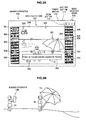
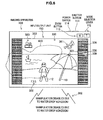
- FIG. 3A is a view illustrating an example of a display screen (display screen 300) displayed on the input/output unit 150 of the first embodiment.
- FIG. 3A illustrates an example of the display screen (display screen 300) in the case where the imaging operation is performed in the state illustrated in FIG. 3B.
- FIG. 3B simply illustrates the case where the imaging operation is performed at a beach with the imaging apparatus 100.
- a transition button 301 making a transition to a menu screen, a moving image capturing operation start button 302, a transition button 303 making a transition to a self-timer setting menu, a smile shutter mode setting button 304, and a help function performing button 305 are displayed on the display screen 300.
- a recording medium notification icon 306, an aspect ratio notification icon 307, an image size notification icon 308, a notification icon 309 notifying the user of the number of recordable images, and a transition button 310 making a transition to a mode switching screen are also displayed on the display screen 300.
- a transition button 311 making a transition to a reproducing mode, a setting mode notification icon 320, a focus frame 321, an F-value notification icon 322, and a message display region 323 are also displayed on the display screen 300.
- the transition button 301 making the transition to the menu screen is an icon that is pressed down in making the transition to the menu screen.
- the transition button 301 making the transition to the menu screen is pressed down, the menu screen is displayed on the input/output unit 150.
- the moving image capturing operation start button 302 is an icon that is pressed down in starting the moving image capturing operation. When the moving image capturing operation start button 302 is pressed down, the mode is set to the moving image capturing mode to start the moving image capturing operation.
- the transition button 303 for making the transition to the self-timer setting menu is an icon that is pressed down to display a self-timer setting menu screen through which a self-timer can be set.
- the transition button 303 making the transition to the self-timer setting menu is pressed down, the self-timer setting menu screen is displayed on the input/output unit 150.
- the smile shutter mode setting button 304 is an icon that is pressed down in setting a smile shutter mode. When the smile shutter mode setting button 304 is pressed down, the smile shutter mode is set.
- the smile shutter mode is an imaging mode in which still image recording processing is automatically performed when a person included in the image data generated by the imaging unit 120 smiles.
- the help function performing button 305 is an icon that is pressed down in performing a help function (guide function). That is, when the help function performing button 305 is pressed down, a screen in which the help function (guide function) is performed is displayed on the input/output unit 150.
- the recording medium notification icon 306 is an icon that shows that the recording medium is the recording target of the image data generated by the imaging unit 120. For example, in the case where the image data generated by the imaging unit 120 is recorded in a memory (for example, recording medium 140) incorporated in the imaging apparatus 100, the icon expressing the memory is displayed as the recording medium notification icon 306.
- the aspect ratio notification icon 307 is an icon that shows an aspect ratio of the image (still image). For example, 4:3 or 16:9 is displayed as the aspect ratio notification icon 307.
- the image size notification icon 308 is an icon that shows an image size of the image (still image). For example, "14M" indicating the image size of 14 megapixels is displayed as the image size notification icon 308.
- the notification icon 309 notifying the user of the number of recordable images is an icon that shows the number of images (still images), which can be recorded in the memory (for example, recording medium 140) incorporated in the imaging apparatus 100.
- a value of "3" indicates that the number of recordable images and is displayed as the notification icon 309 notifying the user of the number of recordable images.
- the transition button 310 for making the transition to the mode switching screen is an icon that is pressed down to display the mode switching screen in which the mode is switched.
- the transition button 3 10 making the transition to the mode switching screen is pressed down, the mode switching screen is displayed on the input/output unit 150.
- the transition button 311 for making the transition to the reproducing mode is a button that is pressed down to transition to the reproducing mode.
- the reproducing mode is set.
- the setting mode notification icon 320 is an icon that shows the currently-set mode. For example, an indicator expressing one of the reproducing mode and the imaging mode (still image capturing mode, panoramic image capturing mode, and moving image capturing mode) is displayed. For example, as illustrated in FIG. 3A , a person imaging mode is set in the case where a person (user 12) is included in the through image (the captured image generated by the imaging unit 120) displayed in a through image display region 330. In this case, an icon expressing the person imaging mode is displayed as the setting mode notification icon 320.
- the focus frame 321 is a frame that is used to specify a target (focusing target) that is brought into focus in the subjects displayed on the input/output unit 150, and the focus frame 321 is displayed as four outline angle brackets near the center of the display screen 300. That is, one or plural subjects is brought into focus in the subjects existing in the focus frame 321.
- the F-value notification icon 322 is an icon that notifies the user of a currently-set F value. For example, in the case where "F3.5" is displayed as the F-value notification icon 322, it means that the currently-set F value is "F3.5".
- the message display region 323 is a region where a message for supporting the manipulation of the user is displayed.
- the through image display region 330 is a region where the through image is displayed. For example, as illustrated in FIG. 3B , in the case where a user 11 performs the imaging operation to the user 12 located near a beach umbrella 13 as a principal subject with the imaging apparatus 100, the through image of the user 12 is displayed on the through image display region 330.
- the icons are displayed on the display screen 300 illustrated in FIG. 3A by way of example.
- the icons are appropriately changed according to the setting mode and the imaging operation state.
- the icons 301 to 305 displayed on the left of the display screen 300, the transition button 310 for making the transition to the mode switching screen, and the transition button 311 for making the transition to the reproducing mode are the manipulation icons that are used when the user performs the manipulation input.
- other icons such as the recording medium notification icon 306 and the aspect ratio notification icon 307 indicate the current state, and are not used when the user performs the manipulation input.
- the imaging operation is performed on a beach with the imaging apparatus 100.
- friends who play on an edge of the water while making brilliant splashes are captured.
- the imaging apparatus 100 has the waterproof function, it is conceivable that the imaging operation is performed on the edge of the water or in a relatively shallow sea. In such imaging operations, it is also conceivable that the imaging apparatus 100 is splashed with water from the sea and the splash adheres to the display surface of the input/output unit 150.
- the manipulation input relating to the manipulation image is performed due to the water adhesion, and possibly an undesired imaging operation (malfunction) is performed based on the manipulation input. Therefore, in the first embodiment of the present disclosure, in the case where the water adheres to the display surface of the input/output unit 150 during the use of the imaging apparatus 100, the erasure of the manipulation image and the processing of disabling the manipulation input relating to the manipulation image are performed in order to prevent the malfunction due to the water adhesion.
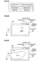
- FIGS. 4A, 4B, and 4C are views illustrating an example of a relationship between water adhering to the display surface of the input/output unit 150 and the operating state of the input/output unit 150 in the first embodiment of the present disclosure.
- FIGS. 4B and 4C the amount of water adhering to the display surface of the input/output unit 150 is described while divided into two stages.
- FIG. 4A illustrates an example of a relationship between the existence or non-existence of the water detected by the water detecting unit 162 and the necessity of the disable processing performed by the control unit 163.
- FIG. 4B simply illustrates water 401 adhering to a display surface 400 of the input/output unit 150
- FIG. 4C simply illustrates water 402 adhering to the display surface 400 of the input/output unit 150.
- FIGS. 4B and 4C also schematically illustrate grounding states of the water 401 1 and water 402, which adhere to the display surface 400, using the numeral 405 that expresses the grounding.
- FIG. 4B also illustrates the case where a relatively small amount of water adheres to the display surface 400
- FIG. 4C also illustrates the case where a relatively large amount of water adheres to the display surface 400.
- the charge has little influence on the manipulation input in the case where the small amount of water 401 (for example, the ratio of the water 401 to the display surface 400 is lower than 30%) adheres to the display surface 400 of the input/output unit 150 and the water 401 is not grounded.
- the water detecting unit 162 does not detect the water 401 adhering to the display surface 400 of the input/output unit 150. Therefore, the control unit 163 determines that the operating state of the input/output unit 150 is in a normal state and performs various kinds of control.
- the control unit 163 determines that the operating state of the input/output unit 150 is in a normal state and performs various kinds of control.
- the control unit 163 determines that the operating state of the input/output unit 150 is in a normal state and performs various kinds of control.
- the water detecting unit 162 detects the water 401 adhering to the display surface 400.
- the charge has large influence on the manipulation input in the case where the large amount of water 402 (for example, the ratio of the water 402 to the display surface 400 is not lower than 30%) adheres to the display surface 400 of the input/output unit 150 and the water 402 is grounded.
- the water detecting unit 162 detects the water 402 adhering to the display surface 400 of the input/output unit 150.
- the control unit 163 performs the processing of disabling the manipulation input relating to the manipulation image displayed on the display surface of the input/output unit 150 and erases the manipulation image that becomes the disabling target.
- FIGS. 5 to 8 illustrate examples in which the disable processing is performed to erase the disabled manipulation image.
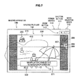
- FIGS. 5 to 8 are views illustrating notification examples in the case where the water adheres to the display surface of the input/output unit 150 in the first embodiment of the present disclosure.
- the amount of water 410 larger than a predetermined amount adheres to the display surface of the input/output unit 150, and the water 410 is grounded. Therefore, the display mode is changed.
- the water 410 is schematically expressed by a bold dotted line for the purpose of the easy description.
- FIGS. 5 to 8 illustrate examples in which only part (the plural manipulation icons used to perform the manipulation input and the warning message) of the display mode on the display surface of the input/output unit 150 is changed.
- FIGS. 5 to 8 illustrate examples in which all the reception of the plural manipulation icons (manipulation images) used to perform the manipulation inputs are disabled to erase all the plural manipulation icons.
- FIG. 5 illustrates a notification example in which the manipulation icon that can be manipulated by the user is erased from the display surface to display a warning icon 351 when the water not less than a predetermined amount adheres to the display surface of the input/output unit 150.
- the warning icon 351 includes an indicator expressing a hand and an indicator expressing prohibition.
- the warning icon 351 may be displayed in a blinking manner so as to be easily recognized by the user or displayed by a color that can be distinguished from other colors.
- the icons 301 to 305, 310, and 311 that are used when the user performs the manipulation input are erased from the display screen 350.
- the icons 306 to 309 and 320 which express the current state but are not used when the user performs the manipulation input, are not erased from the display screen 350.
- the disable processing is performed to the icons that are used when the user performs the manipulation input, and the icons are erased from the display screen 350, so that the manipulation input is hardly performed in the input/output unit 150. Therefore, in the case where the water not less than a predetermined amount adheres to the display surface of the input/output unit 150, the false detection due to the water adhesion can be prevented. Even if the manipulation input is not received by the input/output unit 150, the manipulation input can be performed using the shutter button 111, the mode selector lever 112, the zoom button 113, and the power switch 114. Therefore, even in the case where the user performs the imaging operation, the basic operations (such as the shutter manipulation and the zoom manipulation) of the imaging operation can be performed.
- FIG. 6 illustrates an example in which the manipulation icon that can be manipulated by the user is erased from the display surface to output a warning sound 362 from the sound output unit 170 when the water not less than a predetermined amount adheres to the display surface of the input/output unit 150.
- the warning sound 362 is output instead of displaying the warning icon 351 of FIG. 5 .
- the sound of "manipulation is disabled due to water droplet adhesion!” is repeatedly output. The repetitive output may be stopped after continuously performed for a predetermined time (for example, 10 seconds).
- the warning icon 361 may be displayed such that the user easily recognizes the output of the warning sound 362 even if the surroundings of the imaging apparatus 100 are noisy. Similarly to the warning icon 351, the warning icon 361 may be displayed in the blinking manner so as to be easily recognized by the user or displayed by a color that can be distinguished from other colors.
- a display screen 360 of FIG. 6 differs from the display screen 350 of FIG. 5 only in that the warning icon 361 is displayed instead of the warning icon 351. Therefore, other descriptions are omitted.
- FIG. 7 illustrates an example in which the manipulation icon that can be manipulated by the user is erased from the display surface to display a warning message on a message display region 371 when the water not less than a predetermined amount adheres to the display surface of the input/output unit 150.
- a warning message is output instead of displaying the warning icon 351 of FIG. 5 .
- a message of "manipulation is disabled due to water droplet adhesion!” is displayed in a message display region 371.
- the message is erased after continuously displayed for a predetermined time (for example, 10 seconds), and the warning icon 351 of FIG. 5 may be displayed.
- a display screen 370 of FIG. 7 differs from the display screen 350 of FIG. 5 only in that the warning message is displayed in the message display region 371 instead of the warning icon 351. Therefore, other descriptions are omitted.
- FIG. 8 illustrates an example in which the manipulation icon that can be manipulated by the user is erased from the display surface to display the warning message on a message display region 376 when the water not less than a predetermined amount adheres to the display surface of the input/output unit 150.
- the notification example of FIG. 8 differs from that of FIG. 7 only in contents of the warning message.
- the message of "manipulation of touch panel is disabled due to water droplet adhesion, but manipulation other than touch panel is available!" is displayed in the message display region 3 76.
- the user can be notified that the manipulation input can be performed using the shutter button 111, the mode selector lever 112, the zoom button 113, and the power switch 114.
- the message is erased after continuously displayed for a predetermined time (for example, 10 seconds), and the warning icon 351 of FIG. 5 may be displayed.
- the processing of disabling the manipulation input relating to the manipulation image is performed to erase the manipulation image. Therefore, even if the water adheres to the display surface of the input/output unit 150, the malfunction due to the water adhesion can be prevented.
- the user is notified that the reception of the manipulation input relating to the manipulation image is disabled, so that the user can understand that the reception of the manipulation input relating to the manipulation image is disabled. Therefore, for example, the user can quickly perform processing of wiping the water adhering to the display surface of the input/output unit 150, and the manipulation input can quickly be resumed in the input/output unit 150.
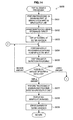
- FIG. 9 is a flowchart illustrating an example of a procedure of manipulation image disabling control processing performed by the imaging apparatus 100 of the first embodiment of the present disclosure.
- all the receptions of the plural manipulation icons (manipulation images) that are used to perform the manipulation inputs are disabled to erase all the plural manipulation icons.
- Step S901 whether an instruction to start a specific operation to perform the manipulation input is issued in the input/output unit 150 is determined.
- the specific operation means the reproducing operation and the imaging operation, in which the manipulation input is performed in the input/output unit 150.
- the instruction to start the specific operation is performed by the user's manipulation using the manipulation receiving unit 110.
- the display control unit 164 When the instruction to start the specific operation is issued (Step S901), the display control unit 164 performs the display processing under the control of the control unit 163 in response to the manipulation input received by the manipulation receiving unit 110 or the receiving unit 151 (Step S902). For example, in the case where the setting manipulation of the still image capturing mode is performed, the display control unit 164 performs control so as to cause the display unit 152 to display the display screen 3 00 of FIG. 3A .
- the water detecting unit 162 performs water detection processing of detecting the water adhering to the display surface of the input/output unit 150 based on the electrostatic sensor information from the receiving unit 151 (Step S903).
- the control unit 163 performs processing of disabling the manipulation input in the input/output unit 150 (Step S905).
- Step S903 is an example of the water detection procedure described in the claims.
- the display control unit 164 then erases the manipulation image (for example, the manipulation icon that is used when the user performs the manipulation input) displayed on the input/output unit 150 (Step S906).
- the display control unit 164 then causes the display unit 152 to display water adhesion warning information (for example, the warning icon 351 of FIG. 5 ) (Step S907).
- the notification that the manipulation input in the input/output unit 150 is disabled is made by the water adhesion warning information.
- Steps S904 to S907 are an example of the water detection procedure described in the claims.
- the water detecting unit 162 then performs the water detection processing of detecting the water adhering to the display surface of the input/output unit 150 based on the electrostatic sensor information from the receiving unit 151 (Step S908).
- the flow returns to Step S908.
- the display processing is performed in response to the manipulation input received by the manipulation receiving unit 110.
- Step S909 When the water is not detected (Step S909), the control unit 163 performs the enable processing of enabling the manipulation input in the input/output unit 150 (Step S910).
- the display control unit 164 causes the display unit 152 to display the manipulation image (Step S911).
- the display control unit 164 erases the displayed water adhesion warning information from the display unit 152 (Step S912), and the flow goes to Step S913.
- Step S904 When the water adhering to the display surface of the input/output unit 150 is not detected (Step S904), whether an instruction to end the specific operation to perform the manipulation input is issued in the input/output unit 150 is determined (Step S913).
- the instruction to end the specific operation is not issued, the flow returns to Step S902.
- the instruction to end the specific operation is the power-off manipulation with the power switch 114.
- the operation of the manipulation image disabling control processing is ended.
- the processing of disabling the manipulation input relating to the manipulation image is performed to erase the manipulation image.
- the manipulation input in the input/output unit can frequently be detected while detection accuracy is degraded.
- first threshold a predetermined amount
- second threshold a second threshold
- a configuration of an imaging apparatus according to the second embodiment of the present disclosure is substantially the same as that of FIGS. 1 and 2 . Therefore, the components that are common with the first embodiment of the present disclosure are designated by the identical numeral, and the description is partially omitted.
- the control unit 163 of FIG. 2 enables only the specific manipulation image in the plural manipulation images.
- the predetermined condition can be determined as follows. That is, in the case where the water adhering to the display surface of the input/output unit 150 is detected (in the case where the water not less than a predetermined amount (first threshold) adheres), the detected water adhesion amount is less than a predetermined amount (second threshold). For example, as illustrated in FIG.
- the control unit 163 causes the display unit 152 to display specific manipulation images (a transition button 561 making the transition to the menu screen and a transition button 562 making the transition to the mode switching screen) to erase other manipulation images except the specific manipulation images.
- specific manipulation images can be enlarged and displayed on the display unit 152.
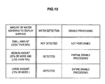
- FIGS. 10 , 11A, 11B, and 11C are views illustrating examples of the relationship between the water adhering to the display surface of the input/output unit 150 and the operating state of the input/output unit 150 in the second embodiment of the present disclosure.
- FIGS. 10 , 11A, 11B, and 11C the amount of water adhering to the display surface of the input/output unit 150 is described while divided into three stages.
- FIG. 10 illustrates an example of the relationship among an amount of water adhering to the display surface of the input/output unit 150, the existence or non-existence of the water detected by the water detecting unit 162 and the necessity of the disable processing performed by the control unit 163.
- FIG. 11A simply illustrates water 501 adhering to a display surface 500 of the input/output unit 150.
- FIG. 11B simply illustrates water 502 adhering to the display surface 500 of the input/output unit 150
- FIG. 11C simply illustrates water 503 adhering to the display surface 500 of the input/output unit 150.
- FIGS. 11A to 11C like FIGS. 4B and 4C , also schematically illustrate grounding states of the water 501 to water 503, which adhere to the display surface 500, using the numeral 505 that expresses the grounding.
- FIG. 11A also illustrates the case in which a relatively small amount of water adheres to the display surface 500
- FIG. 11B also illustrates the case in which a medium amount of water adheres to the display surface 500
- FIG. 11C also illustrates the case in which a relatively large amount of water adheres to the display surface 500.
- the charge has little influence on the manipulation input in the case where the small amount of water 501 (for example, the ratio of the water 501 to the display surface 500 is lower than 30%) adheres to the display surface 500 of the input/output unit 150 and the water 501 is not grounded.
- the water detecting unit 162 does not detect the water 501 adhering to the display surface 500 of the input/output unit 150. Therefore, similarly to the example of FIG. 4B , the control unit 163 determines that the operating state of the input/output unit 150 is in a normal state and performs various kinds of control.
- the water detecting unit 162 detects the water 501 adhering to the display surface 500.
- the charge has large influence on the manipulation input in the case where the large amount of water 503 (for example, the ratio of the water 503 to the display surface 500 is not lower than 70%) adheres to the display surface 500 of the input/output unit 150 and the water 503 is grounded.
- the water detecting unit 162 detects the water 503 adhering to the display surface 500 of the input/output unit 150.
- the control unit 163 performs the processing of disabling the manipulation input relating to the manipulation image displayed on the display surface of the input/output unit 150 and erases the manipulation image that becomes the disable target.
- FIGS. 5 to 8 illustrate examples in which the disabling processing is performed to erase the disabled manipulation image.
- the charge also has large influence on the manipulation input in the case where the medium amount of water 502 (for example, the ratio of the water 502 to the display surface 500 is not lower than 30% and lower than 70%) adheres to the display surface 500 of the input/output unit 150 and the water 502 is grounded.
- the water detecting unit 162 detects the water 502 adhering to the display surface 500 of the input/output unit 150.
- the control unit 163 performs the processing of disabling a part (except the specific manipulation image) of the manipulation inputs relating to the manipulation images displayed on the display surface of the input/output unit 150 and erases the manipulation images that become the disable targets.
- the control unit 163 enables the manipulation input relating to the specific manipulation image and enlarges the specific manipulation image.
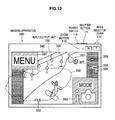
- FIG. 12 illustrates the example in which the manipulation inputs relating to the specific manipulation images are enabled to enlarge the specific manipulation images.
- FIG. 12 is a view illustrating a display example in the case where the water adheres to the display surface of the input/output unit 150 in the second embodiment of the present disclosure.
- the imaging operation is performed in a ski resort with the imaging apparatus 100.
- the pouring snow falls on the imaging apparatus 100 and the snow adhering to the display surface of the input/output unit 150 is melted to become water.
- FIG. 12 similarly to the example of FIG. 11B , the medium amount of water 550 adheres to the display surface of the input/output unit 150, and the water 550 is grounded.
- the water 550 is schematically expressed by a bold dotted line for the purpose of the easy description.
- FIG. 12 illustrates an example in which only part (the plural manipulation icons used to perform the manipulation input and the warning message) of the display mode on the display surface of the input/output unit 150 is changed.
- FIG. 12 illustrates an example in which a part (except the specific manipulation image) of the receptions of the plural manipulation icons (manipulation images) used to perform the manipulation inputs are disabled to erase the plural manipulation icons that become the disable targets.
- the part of the manipulation icons that can be manipulated by the user's manipulation is erased from the display surface, and the warning icon 351 is displayed while only the specific manipulation icon is enlarged and displayed on the display surface.
- the warning icon 351 is similar to that of FIG. 5 .
- Examples of the specific manipulation image include a manipulation icon used to set the frequently-used function and a manipulation icon set by the user's manipulation.
- FIG. 12 illustrates an example in which the transition button 561 making the transition to the menu screen and the transition button 562 making the transition to the mode switching screen are set in the specific manipulation icon.
- the transition button 561 making the transition to the menu screen and the transition button 562 making the transition to the mode switching screen correspond to the transition button 301 making the transition to the menu screen and the transition button 310 making the transition to the mode switching screen of FIG 3A .
- the disable processing is performed to the manipulation icons except the specific manipulation icon, and the manipulation icons are erased from the display screen 540, so that the manipulation input is not selected by the input/output unit 150. Therefore, in the case where the water not less than a predetermined amount adheres to the display surface of the input/output unit 150, the false detection due to the water adhesion can be prevented.
- the specific manipulation icon is maintained in the enabled state without performing the disable processing, and enlarged and displayed on the display screen 540, which allows the manipulation input to be performed in the input/output unit 150. Therefore, the manipulation icon used to set the frequently-used function can be used even if the medium amount of water adheres to the display surface of the input/output unit 150. The false detection due to the water adhesion can be prevented by enlarging and displaying the specific manipulation icon, in the case where the water not less than a predetermined amount adheres to the display surface of the input/output unit 150.
- the region where the specific manipulation icon is enlarged and displayed on the display surface of the input/output unit 150 is a region to which the water does not adhere.
- the control unit 163 specifies the region to which the water does not adhere in the display surface of the input/output unit 150 based on the water detection information (the shape of the contact range in the display surface of the input/output unit 150) from the water detecting unit 162.
- the control unit 163 enlarges and displays the specific manipulation icon in the region to which the water does not adhere in the display surface of the input/output unit 150.
- the control unit 163 may appropriately change the display mode of the specific manipulation icon according to the shape of the region to which the water does not adhere and the number of specific manipulation icons.
- the transition button 561 making the transition to the menu screen and the transition button 562 making the transition to the mode switching screen are displayed in the region to which the water 550 does not adhere in the display surface of the input/output unit 150.
- the user may be notified that only the specific manipulation icon is maintained in the enabled state while the disable processing is performed to other manipulation icons to erase other manipulation icons.
- FIG. 13 is a flowchart illustrating an example of a procedure of manipulation image disabling control processing performed by the imaging apparatus 100 according to the second embodiment of the present disclosure.
- the plural manipulation icons used to perform the manipulation inputs
- only the specific manipulation icon is enabled and enlarged and displayed on the display surface while the other manipulation icons are disabled and erased.
- the processing procedure of FIG. 13 is a modification of FIG. 9
- the portion common with FIG. 9 is designated by the identical numeral, and the description is omitted.
- Step S903 Whether the small, medium, or large amount of water is detected as the detection result through the water detection processing (Step S903) is determined (Step S921).
- Step S930 When the medium amount of water is detected as the detection result through the water detection processing (Step S903), the partial disable processing is performed (Step S930). The partial disable processing is described in detail with reference to FIG. 14 .
- Step S950 When the large amount of water is detected as the detection result through the water detection processing is (Step S950). The entire disable processing is described in detail with reference to FIG. 15 .
- FIG. 14 is a flowchart illustrating an example of the partial disable processing (procedure of processing in Step S930 of FIG. 13 ) in the procedure of the manipulation image disabling control processing performed by the imaging apparatus 100 according to the second embodiment of the present disclosure.
- the control unit 163 performs the processing of disabling a part (manipulation icons except the specific manipulation icon) of manipulation inputs in the input/output unit 150 (Step S931).
- the display control unit 164 then erases the manipulation image (for example, the manipulation icon except the specific manipulation icon) that becomes the disable target in the manipulation images displayed on the input/output unit 150 (Step S932).
- the display control unit 164 causes the display unit 152 to display the water adhesion warning information (for example, the warning icon 351 of FIG. 12 ) (Step S933).
- the display control unit 164 then performs the display processing under the control of the control unit 163 in response to the manipulation input received by the manipulation receiving unit 110 or the receiving unit 151 (Step S934).
- the water detecting unit 162 then performs the water detection processing of detecting the water adhering to the display surface of the input/output unit 150 based on the electrostatic sensor information from the receiving unit 151 (Step S935). Whether the small, medium, or large amount of water is detected as the detection result through the water detection processing is determined (Step S936).
- Step S935 When the small amount of water is detected as the detection result through the water detection processing (Step S935) (Step S936), the control unit 163 performs processing of enabling all the manipulation inputs in the input/output unit 150 (Step S937).
- the display control unit 164 then causes the display unit 152 to display all the manipulation images (Step S938).
- the display control unit 164 then erases the displayed water adhesion warning information from the display unit 152 (Step S939).
- Step S935 When the medium amount of water is detected as the detection result through the water detection processing (Step S935) (Step S936), the flow returns to Step S934.
- Step S935 When the large amount of water is detected as the detection result through the water detection processing (Step S935) (Step S936), the flow goes to Step S951 of FIG. 15 .
- FIG. 15 is a flowchart illustrating an example of the entire disable processing (procedure of processing in Step S950 of FIG. 13 ) in the procedure of the manipulation image disabling control processing performed by the imaging apparatus 100 according to the second embodiment of the present disclosure.
- the control unit 163 performs the processing of disabling all the manipulation inputs in the input/output unit 150 (Step S951).
- the display control unit 164 then erases the manipulation images displayed on the input/output unit 150 (Step S952).
- the display control unit 164 then causes the display unit 152 to display the water adhesion warning information (for example, the warning icon 351 of FIG. 12 ) (Step S953).
- the water detecting unit 162 then performs the water detection processing of detecting the water adhering to the display surface of the input/output unit 150 based on the electrostatic sensor information from the receiving unit 151 (Step S954). Whether the small, medium, or large amount of water is detected as the detection result through the water detection processing is determined (Step S955). While the water is detected (Steps S954 and S955), the display processing is performed in response to the manipulation input received by the manipulation receiving unit 110.
- Step S954 the control unit 163 performs the processing of enabling all the manipulation inputs in the input/output unit 150 (Step S956).
- the display control unit 164 then causes the display unit 152 to display all the manipulation images (Step S957).
- the display control unit 164 then erases the displayed water adhesion warning information from the display unit 152 (Step S958).
- Step S954 When the large amount of water is detected as the detection result through the water detection processing (Step S954) (Step S955), the flow returns to Step S954.
- Step S954 the control unit 163 performs the processing of enabling a part (specific manipulation icon) of manipulation inputs in the input/output unit 150 (Step S940).
- the display control unit 164 then causes the display unit 152 to display the manipulation image (for example, the specific manipulation icon) that becomes the enable target (Step S941).
- the display control unit 164 then causes the display unit 152 to display the water adhesion warning information (for example, the warning icon 351 of FIG. 12 ) (Step S942), and the flow goes to Step S934 of FIG. 14 .
- the water adhesion warning information may be changed and displayed according to the case in which a part of manipulation inputs in the input/output unit 150 is disabled or the case in which all the manipulation inputs are disabled.
- the second embodiment of the present disclosure even if the water adheres to the display surface of the input/output unit 150, only the specific manipulation icon is enlarged and displayed on the display surface when the adhesion water amount is less than the predetermined amount (second threshold). In this case, the false detection due to the water detection can be prevented because the specific manipulation icon is displayed in the portion to which the water does not adhere in the display surface of the input/output unit 150. According to the second embodiment of the present disclosure, even if the water adheres to the display surface of the input/output unit 150, the user's manipulation is received as much as possible while the malfunction is prevented during the water adhesion.
- the manipulation icon in which the reception of the manipulation input is disabled is erased from the display unit 152.
- the disabled manipulation icon is not erased from the display unit 152, but the notification (for example, disable display) that the manipulation icon is disabled may be made.
- the imaging apparatus 100 is splashed with the water.
- the embodiments can also be applied to the case where the imaging apparatus 100 is used in the water (for example, underwater photography).
- the processing of disabling the manipulation inputs relating to all the manipulation images is performed to erase the manipulation images.
- the notification for example, disable display
- the water adhering to the display surface of the input/output unit 150 is detected.
- the embodiments can also be applied to the case where the imaging apparatus 100 is splashed with other liquid (for example, juice) than the water due to a trouble. That is, the embodiments of the present disclosure can be applied to the liquid that is generally detected as moisture.
- the user is notified using the display of the warning icon or warning message and the output of the warning sound.
- another notification method may be adopted.
- the user may be notified by vibration of the imaging apparatus.
- the imaging apparatus has been described as an example of the electronic apparatus.
- the embodiments of the present disclosure can be applied to another electronic apparatus including the input/output unit.
- the embodiments can be applied to the electronic apparatus, such as a game machine, a mobile phone, a digital home electrical appliance (for example, cooking machine such as a rice cooker), a navigation system, and a portable media player, which are provided with touch panels.
- the electronic apparatus including the input/output unit has been described by way of example.
- the embodiments of the present disclosure can be applied to an electronic apparatus that conducts communication with an external input/output unit to control the input/output unit.
- the processing procedure described in the embodiments of the present disclosure may be recognized as a method including a series of procedures, a program that causes a computer to.execute the series of procedures, or the recording medium in which the program is stored.
- a CD Compact Disc
- MD Mini Disc
- DVD Digital Versatile Disk
- a memory card e.g., a hard disk drive
- Blu-ray Disc registered trademark
Landscapes
- Engineering & Computer Science (AREA)
- Signal Processing (AREA)
- Human Computer Interaction (AREA)
- Multimedia (AREA)
- General Engineering & Computer Science (AREA)
- Theoretical Computer Science (AREA)
- General Physics & Mathematics (AREA)
- Physics & Mathematics (AREA)
- Computer Networks & Wireless Communication (AREA)
- Studio Devices (AREA)
- User Interface Of Digital Computer (AREA)
- Devices For Indicating Variable Information By Combining Individual Elements (AREA)
- Position Input By Displaying (AREA)
- Control Of Indicators Other Than Cathode Ray Tubes (AREA)
Applications Claiming Priority (1)
| Application Number | Priority Date | Filing Date | Title |
|---|---|---|---|
| JP2010276129A JP5678631B2 (ja) | 2010-12-10 | 2010-12-10 | 電子機器、電子機器の制御方法およびプログラム |
Publications (2)
| Publication Number | Publication Date |
|---|---|
| EP2464099A2 true EP2464099A2 (fr) | 2012-06-13 |
| EP2464099A3 EP2464099A3 (fr) | 2013-10-30 |
Family
ID=45421850
Family Applications (1)
| Application Number | Title | Priority Date | Filing Date |
|---|---|---|---|
| EP11191464.4A Withdrawn EP2464099A3 (fr) | 2010-12-10 | 2011-12-01 | Dispositif d'affichage d'images incluant un détecteur de liquide |
Country Status (6)
| Country | Link |
|---|---|
| US (1) | US20120146924A1 (fr) |
| EP (1) | EP2464099A3 (fr) |
| JP (1) | JP5678631B2 (fr) |
| KR (1) | KR20120065233A (fr) |
| CN (1) | CN102547110A (fr) |
| TW (1) | TW201239741A (fr) |
Cited By (5)
| Publication number | Priority date | Publication date | Assignee | Title |
|---|---|---|---|---|
| EP2821897A1 (fr) | 2013-07-04 | 2015-01-07 | Sony Corporation | Détection de doigt sur écrans tactiles pour dispositifs mobiles |
| WO2015092689A1 (fr) * | 2013-12-19 | 2015-06-25 | Sony Corporation | Dispositif d'entrée alternative pour des simulations de pression/libération |
| WO2015102685A1 (fr) * | 2013-12-31 | 2015-07-09 | General Electric Company | Dispositif d'affichage à écran tactile et procédé de commande d'entrée tactile |
| EP3198387A4 (fr) * | 2014-09-26 | 2018-06-06 | Rakuten, Inc. | Procédé et système pour détecter de l'eau, des débris ou d'autres objets étrangers sur un écran d'affichage |
| EP4354838A4 (fr) * | 2021-06-09 | 2024-10-09 | ZTE Corporation | Procédé et appareil pour identifier un risque d'entrée d'eau d'un terminal, dispositif et support de stockage |
Families Citing this family (38)
| Publication number | Priority date | Publication date | Assignee | Title |
|---|---|---|---|---|
| JP3485874B2 (ja) * | 2000-10-04 | 2004-01-13 | 富士通日立プラズマディスプレイ株式会社 | Pdpの駆動方法および表示装置 |
| JP5121963B2 (ja) * | 2011-03-31 | 2013-01-16 | 株式会社東芝 | 電子機器及び制御方法 |
| JP5906097B2 (ja) * | 2012-01-31 | 2016-04-20 | キヤノン株式会社 | 電子機器、その制御方法、プログラム、及び記録媒体 |
| JP5970937B2 (ja) * | 2012-04-25 | 2016-08-17 | ソニー株式会社 | 表示制御装置および表示制御方法 |
| KR20140021821A (ko) * | 2012-08-09 | 2014-02-21 | 삼성전자주식회사 | 이미지 캡처 장치 및 이미지 캡처 방법 |
| KR20140091297A (ko) * | 2013-01-11 | 2014-07-21 | 삼성전자주식회사 | 터치 감도 제어 방법 및 그 전자 장치 |
| US10101900B2 (en) * | 2013-01-16 | 2018-10-16 | Sony Corporation | Information processing device and method of processing information |
| SG2014010144A (en) * | 2013-02-20 | 2014-08-28 | Panasonic Corp | Control method for information apparatus and program |
| KR102063915B1 (ko) | 2013-03-14 | 2020-01-08 | 삼성전자주식회사 | 사용자 기기 및 그 동작 방법 |
| KR102065411B1 (ko) * | 2013-09-04 | 2020-01-13 | 엘지전자 주식회사 | 이동 단말기 및 이의 제어 방법 |
| US9615193B1 (en) * | 2013-12-13 | 2017-04-04 | Symantec Corporation | Systems and methods for managing launch activities on a mobile device |
| US9207804B2 (en) * | 2014-01-07 | 2015-12-08 | Lenovo Enterprise Solutions PTE. LTD. | System and method for altering interactive element placement based around damaged regions on a touchscreen device |
| US9310934B2 (en) * | 2014-02-21 | 2016-04-12 | Qualcomm Incorporated | Systems and methods of moisture detection and false touch rejection on touch screen devices |
| US20150277720A1 (en) * | 2014-03-28 | 2015-10-01 | Google Technology Holdings LLC | Systems and Methods for Managing Operating Modes of an Electronic Device |
| JP6267060B2 (ja) * | 2014-05-30 | 2018-01-24 | Dmg森精機株式会社 | 操作装置 |
| CN104063101B (zh) | 2014-05-30 | 2016-08-24 | 小米科技有限责任公司 | 触摸屏控制方法和装置 |
| CN104156120B (zh) * | 2014-08-22 | 2019-03-15 | Oppo广东移动通信有限公司 | 一种触控方式的切换方法、装置及移动设备 |
| US9916037B2 (en) * | 2014-09-26 | 2018-03-13 | Rakuten Kobo, Inc. | Method and system for mobile device splash mode operation and transition thereto |
| US20160162146A1 (en) * | 2014-12-04 | 2016-06-09 | Kobo Incorporated | Method and system for mobile device airspace alternate gesture interface and invocation thereof |
| JP2016149026A (ja) * | 2015-02-12 | 2016-08-18 | 富士通株式会社 | 電子機器、及び、表示制御プログラム |
| US10437384B2 (en) * | 2015-03-13 | 2019-10-08 | Parade Technologies, Ltd. | Water detection and wipe detection algorithms for touchscreen proximity sensing |
| JP6140217B2 (ja) | 2015-05-12 | 2017-05-31 | 京セラ株式会社 | 電子機器、制御方法及び制御プログラム |
| JP6141352B2 (ja) | 2015-05-12 | 2017-06-07 | 京セラ株式会社 | 電子機器及び制御プログラム |
| JP6464046B2 (ja) | 2015-06-26 | 2019-02-06 | 京セラ株式会社 | 電子機器、制御方法及び制御プログラム |
| JP6484129B2 (ja) | 2015-06-29 | 2019-03-13 | 京セラ株式会社 | 電子機器、画像表示方法及び画像表示プログラム |
| JP6153570B2 (ja) * | 2015-07-24 | 2017-06-28 | 京セラ株式会社 | 電子機器 |
| JP6261546B2 (ja) | 2015-08-31 | 2018-01-17 | 京セラ株式会社 | 携帯機器、制御方法及び制御プログラム |
| JP6739193B2 (ja) * | 2016-03-14 | 2020-08-12 | 三菱電機株式会社 | タッチパネル |
| TWI585664B (zh) * | 2016-04-01 | 2017-06-01 | 意象無限股份有限公司 | Touch panel identification method |
| CN106354261B (zh) * | 2016-09-05 | 2019-07-09 | 广东小天才科技有限公司 | 一种移动设备输入方式的切换方法及装置、移动设备 |
| CN106618187A (zh) * | 2016-10-12 | 2017-05-10 | 广东美的厨房电器制造有限公司 | 用于家用电器的防溢出方法、防溢出设备及家用电器 |
| KR20180102262A (ko) * | 2017-03-07 | 2018-09-17 | 엘지전자 주식회사 | 이동 단말기 |
| JP6163278B1 (ja) * | 2017-04-12 | 2017-07-12 | 京セラ株式会社 | 電子機器、プログラムおよび制御方法 |
| JP2018182616A (ja) * | 2017-04-18 | 2018-11-15 | 京セラ株式会社 | 電子機器、制御方法、およびプログラム |
| CN116420132A (zh) | 2020-11-06 | 2023-07-11 | 三星电子株式会社 | 用于感测水分引入的电子装置及其操作方法 |
| EP4359895A4 (fr) | 2021-06-24 | 2025-04-30 | ICU Medical, Inc. | Écran tactile de pompe à perfusion à rejet de fausse touche |
| JP2024016621A (ja) * | 2022-07-26 | 2024-02-07 | キヤノン株式会社 | 撮像装置、制御方法およびプログラム |
| US12271558B2 (en) * | 2023-07-06 | 2025-04-08 | Google Llc | Automatic liquid detection |
Citations (2)
| Publication number | Priority date | Publication date | Assignee | Title |
|---|---|---|---|---|
| JP2009212980A (ja) | 2008-03-05 | 2009-09-17 | Sony Corp | 撮像装置、その制御方法およびプログラム |
| JP2010276129A (ja) | 2009-05-29 | 2010-12-09 | Nissin Kogyo Co Ltd | 車両用ディスクブレーキ |
Family Cites Families (21)
| Publication number | Priority date | Publication date | Assignee | Title |
|---|---|---|---|---|
| JPH05250545A (ja) * | 1992-03-06 | 1993-09-28 | Hitachi Ltd | 自動取引装置 |
| US5526422A (en) * | 1994-06-20 | 1996-06-11 | At&T Corp. | System and method for cleaning the display screen of a touch screen device |
| US20080278408A1 (en) * | 1999-05-04 | 2008-11-13 | Intellimat, Inc. | Floor display systems and additional display systems, and methods and computer program products for using floor display systems and additional display system |
| JP2002123366A (ja) * | 2000-10-17 | 2002-04-26 | Matsushita Electric Ind Co Ltd | タッチスクリーン入力制御システム |
| GB0211901D0 (en) * | 2002-05-23 | 2002-07-03 | Koninkl Philips Electronics Nv | Management of interaction opportunity data |
| JP4378999B2 (ja) * | 2003-05-27 | 2009-12-09 | パナソニック株式会社 | 情報端末機器および該機器を給湯器に適用した給湯器遠隔操作装置 |
| JP5103169B2 (ja) * | 2005-03-25 | 2012-12-19 | シチズンホールディングス株式会社 | 電子機器および表示制御方法 |
| JP4802877B2 (ja) * | 2006-06-14 | 2011-10-26 | パナソニック株式会社 | 加熱調理器 |
| US20080136784A1 (en) * | 2006-12-06 | 2008-06-12 | Motorola, Inc. | Method and device for selectively activating a function thereof |
| US8902172B2 (en) * | 2006-12-07 | 2014-12-02 | Cypress Semiconductor Corporation | Preventing unintentional activation of a touch-sensor button caused by a presence of conductive liquid on the touch-sensor button |
| US20080284756A1 (en) * | 2007-05-15 | 2008-11-20 | Chih-Feng Hsu | Method and device for handling large input mechanisms in touch screens |
| JP2009080683A (ja) * | 2007-09-26 | 2009-04-16 | Pioneer Electronic Corp | タッチパネル型表示装置、その制御方法、プログラム及び記憶媒体 |
| KR20090047828A (ko) * | 2007-11-08 | 2009-05-13 | 삼성전자주식회사 | 컨텐츠 표시 방법 및 이를 적용한 전자기기 |
| US8525796B2 (en) * | 2007-12-21 | 2013-09-03 | International Business Machines Corporation | Self-healing and diagnostic screen |
| US8489141B2 (en) * | 2008-06-27 | 2013-07-16 | Kyocera Corporation | Portable electronic apparatus |
| KR20100062077A (ko) * | 2008-12-01 | 2010-06-10 | 삼성전자주식회사 | 사용자 인터페이스를 향상시키기 위한 사용자 인터페이스 제공방법 및 이를 이용한 멀티미디어 기기 |
| US20100138680A1 (en) * | 2008-12-02 | 2010-06-03 | At&T Mobility Ii Llc | Automatic display and voice command activation with hand edge sensing |
| JP5330043B2 (ja) * | 2009-03-19 | 2013-10-30 | オリンパスイメージング株式会社 | 画像表示装置および画像表示装置の制御方法 |
| JP5316252B2 (ja) * | 2009-06-19 | 2013-10-16 | 株式会社Jvcケンウッド | 情報表示装置、ナビゲーション装置、プログラムおよび表示形態変更方法 |
| US20110252357A1 (en) * | 2010-04-07 | 2011-10-13 | Imran Chaudhri | Device, Method, and Graphical User Interface for Managing Concurrently Open Software Applications |
| JP4994489B2 (ja) * | 2010-10-19 | 2012-08-08 | パナソニック株式会社 | タッチパネル装置 |
-
2010
- 2010-12-10 JP JP2010276129A patent/JP5678631B2/ja not_active Expired - Fee Related
-
2011
- 2011-11-21 US US13/301,365 patent/US20120146924A1/en not_active Abandoned
- 2011-11-28 TW TW100143563A patent/TW201239741A/zh unknown
- 2011-12-01 EP EP11191464.4A patent/EP2464099A3/fr not_active Withdrawn
- 2011-12-02 CN CN2011103965120A patent/CN102547110A/zh active Pending
- 2011-12-02 KR KR1020110128105A patent/KR20120065233A/ko not_active Withdrawn
Patent Citations (2)
| Publication number | Priority date | Publication date | Assignee | Title |
|---|---|---|---|---|
| JP2009212980A (ja) | 2008-03-05 | 2009-09-17 | Sony Corp | 撮像装置、その制御方法およびプログラム |
| JP2010276129A (ja) | 2009-05-29 | 2010-12-09 | Nissin Kogyo Co Ltd | 車両用ディスクブレーキ |
Cited By (9)
| Publication number | Priority date | Publication date | Assignee | Title |
|---|---|---|---|---|
| EP2821897A1 (fr) | 2013-07-04 | 2015-01-07 | Sony Corporation | Détection de doigt sur écrans tactiles pour dispositifs mobiles |
| WO2015001449A1 (fr) | 2013-07-04 | 2015-01-08 | Sony Corporation | Détection de doigt sur écrans tactiles de dispositifs mobiles |
| US9606681B2 (en) | 2013-07-04 | 2017-03-28 | Sony Corporation | Finger detection on touch screens for mobile devices |
| WO2015092689A1 (fr) * | 2013-12-19 | 2015-06-25 | Sony Corporation | Dispositif d'entrée alternative pour des simulations de pression/libération |
| WO2015102685A1 (fr) * | 2013-12-31 | 2015-07-09 | General Electric Company | Dispositif d'affichage à écran tactile et procédé de commande d'entrée tactile |
| US10067606B2 (en) | 2013-12-31 | 2018-09-04 | General Electric Company | Touch screen display device and method of touch input control |
| EP3198387A4 (fr) * | 2014-09-26 | 2018-06-06 | Rakuten, Inc. | Procédé et système pour détecter de l'eau, des débris ou d'autres objets étrangers sur un écran d'affichage |
| EP4354838A4 (fr) * | 2021-06-09 | 2024-10-09 | ZTE Corporation | Procédé et appareil pour identifier un risque d'entrée d'eau d'un terminal, dispositif et support de stockage |
| US12549656B2 (en) | 2021-06-09 | 2026-02-10 | Interdigital Patent Holdings, Inc. | Method, apparatus and device for identifying water ingress risk of terminal, and storage medium |
Also Published As
| Publication number | Publication date |
|---|---|
| JP5678631B2 (ja) | 2015-03-04 |
| JP2012123740A (ja) | 2012-06-28 |
| TW201239741A (en) | 2012-10-01 |
| KR20120065233A (ko) | 2012-06-20 |
| EP2464099A3 (fr) | 2013-10-30 |
| CN102547110A (zh) | 2012-07-04 |
| US20120146924A1 (en) | 2012-06-14 |
Similar Documents
| Publication | Publication Date | Title |
|---|---|---|
| EP2464099A2 (fr) | Dispositif d'affichage d'images incluant un détecteur de liquide | |
| CN101388965B (zh) | 数据处理装置和数据处理方法 | |
| US8730367B2 (en) | Image pickup apparatus that displays images in parallel on display unit having touch panel function and other display unit, control method therefor, and storage medium | |
| JP5116514B2 (ja) | 撮像装置および表示制御方法 | |
| JP2012138012A (ja) | 表示制御装置および方法 | |
| US10715719B2 (en) | Image capturing apparatus and control method thereof | |
| US11671699B2 (en) | Electronic device and control method for controlling the same | |
| US9671932B2 (en) | Display control apparatus and control method thereof | |
| US10324597B2 (en) | Electronic apparatus and method for controlling the same | |
| JP2013255203A (ja) | 撮像装置およびその制御方法、プログラム並びに記憶媒体 | |
| US11252330B2 (en) | Display control apparatus and control method therefor | |
| JP5473349B2 (ja) | 撮像装置、その制御方法、プログラムおよび記憶媒体 | |
| WO2021140746A1 (fr) | Dispositif d'imagerie, procédé de traitement d'informations, et programme | |
| JP2012134942A (ja) | 表示制御装置及びその制御方法 | |
| JP2013126163A (ja) | 動画記録装置及びその制御方法 | |
| US11112907B2 (en) | Electronic device and method for controlling same | |
| JP2021145240A (ja) | 撮像装置 | |
| US11064128B2 (en) | Exposure setting apparatus, control method thereof, and storage medium | |
| JP4647538B2 (ja) | 撮影装置及び表示方法 | |
| KR101595261B1 (ko) | 디지털 촬영 장치, 그 제어 방법, 및 컴퓨터로 읽을 수 있는 저장매체 | |
| JP2008176448A (ja) | 画像表示装置及び画像表示方法 | |
| KR20070121457A (ko) | 디지털 영상 처리 방법 | |
| US10419659B2 (en) | Electronic device and control method thereof to switch an item for which a setting value to be changed | |
| JP2006109137A (ja) | 画像処理装置 | |
| JP2007214774A (ja) | 撮像装置 |
Legal Events
| Date | Code | Title | Description |
|---|---|---|---|
| PUAI | Public reference made under article 153(3) epc to a published international application that has entered the european phase |
Free format text: ORIGINAL CODE: 0009012 |
|
| 17P | Request for examination filed |
Effective date: 20111201 |
|
| AK | Designated contracting states |
Kind code of ref document: A2 Designated state(s): AL AT BE BG CH CY CZ DE DK EE ES FI FR GB GR HR HU IE IS IT LI LT LU LV MC MK MT NL NO PL PT RO RS SE SI SK SM TR |
|
| AX | Request for extension of the european patent |
Extension state: BA ME |
|
| PUAL | Search report despatched |
Free format text: ORIGINAL CODE: 0009013 |
|
| AK | Designated contracting states |
Kind code of ref document: A3 Designated state(s): AL AT BE BG CH CY CZ DE DK EE ES FI FR GB GR HR HU IE IS IT LI LT LU LV MC MK MT NL NO PL PT RO RS SE SI SK SM TR |
|
| AX | Request for extension of the european patent |
Extension state: BA ME |
|
| RIC1 | Information provided on ipc code assigned before grant |
Ipc: H04N 5/232 20060101AFI20130926BHEP Ipc: G06F 3/041 20060101ALI20130926BHEP Ipc: G06F 3/048 20130101ALI20130926BHEP |
|
| STAA | Information on the status of an ep patent application or granted ep patent |
Free format text: STATUS: THE APPLICATION HAS BEEN WITHDRAWN |
|
| 18W | Application withdrawn |
Effective date: 20150107 |