EP2464113A1 - Vorrichtung zur erstellung von fahrzeugumgebungsbildern - Google Patents
Vorrichtung zur erstellung von fahrzeugumgebungsbildern Download PDFInfo
- Publication number
- EP2464113A1 EP2464113A1 EP10806367A EP10806367A EP2464113A1 EP 2464113 A1 EP2464113 A1 EP 2464113A1 EP 10806367 A EP10806367 A EP 10806367A EP 10806367 A EP10806367 A EP 10806367A EP 2464113 A1 EP2464113 A1 EP 2464113A1
- Authority
- EP
- European Patent Office
- Prior art keywords
- vehicle
- image
- fish
- viewing point
- image generation
- Prior art date
- Legal status (The legal status is an assumption and is not a legal conclusion. Google has not performed a legal analysis and makes no representation as to the accuracy of the status listed.)
- Granted
Links
Images



Classifications
-
- B—PERFORMING OPERATIONS; TRANSPORTING
- B60—VEHICLES IN GENERAL
- B60R—VEHICLES, VEHICLE FITTINGS, OR VEHICLE PARTS, NOT OTHERWISE PROVIDED FOR
- B60R1/00—Optical viewing arrangements; Real-time viewing arrangements for drivers or passengers using optical image capturing systems, e.g. cameras or video systems specially adapted for use in or on vehicles
- B60R1/20—Real-time viewing arrangements for drivers or passengers using optical image capturing systems, e.g. cameras or video systems specially adapted for use in or on vehicles
- B60R1/22—Real-time viewing arrangements for drivers or passengers using optical image capturing systems, e.g. cameras or video systems specially adapted for use in or on vehicles for viewing an area outside the vehicle, e.g. the exterior of the vehicle
- B60R1/23—Real-time viewing arrangements for drivers or passengers using optical image capturing systems, e.g. cameras or video systems specially adapted for use in or on vehicles for viewing an area outside the vehicle, e.g. the exterior of the vehicle with a predetermined field of view
- B60R1/27—Real-time viewing arrangements for drivers or passengers using optical image capturing systems, e.g. cameras or video systems specially adapted for use in or on vehicles for viewing an area outside the vehicle, e.g. the exterior of the vehicle with a predetermined field of view providing all-round vision, e.g. using omnidirectional cameras
-
- B—PERFORMING OPERATIONS; TRANSPORTING
- B60—VEHICLES IN GENERAL
- B60R—VEHICLES, VEHICLE FITTINGS, OR VEHICLE PARTS, NOT OTHERWISE PROVIDED FOR
- B60R1/00—Optical viewing arrangements; Real-time viewing arrangements for drivers or passengers using optical image capturing systems, e.g. cameras or video systems specially adapted for use in or on vehicles
- B60R1/20—Real-time viewing arrangements for drivers or passengers using optical image capturing systems, e.g. cameras or video systems specially adapted for use in or on vehicles
- B60R1/22—Real-time viewing arrangements for drivers or passengers using optical image capturing systems, e.g. cameras or video systems specially adapted for use in or on vehicles for viewing an area outside the vehicle, e.g. the exterior of the vehicle
- B60R1/28—Real-time viewing arrangements for drivers or passengers using optical image capturing systems, e.g. cameras or video systems specially adapted for use in or on vehicles for viewing an area outside the vehicle, e.g. the exterior of the vehicle with an adjustable field of view
-
- G—PHYSICS
- G06—COMPUTING OR CALCULATING; COUNTING
- G06T—IMAGE DATA PROCESSING OR GENERATION, IN GENERAL
- G06T3/00—Geometric image transformations in the plane of the image
- G06T3/04—Context-preserving transformations, e.g. by using an importance map
- G06T3/047—Fisheye or wide-angle transformations
-
- H—ELECTRICITY
- H04—ELECTRIC COMMUNICATION TECHNIQUE
- H04N—PICTORIAL COMMUNICATION, e.g. TELEVISION
- H04N7/00—Television systems
- H04N7/18—Closed-circuit television [CCTV] systems, i.e. systems in which the video signal is not broadcast
-
- H—ELECTRICITY
- H04—ELECTRIC COMMUNICATION TECHNIQUE
- H04N—PICTORIAL COMMUNICATION, e.g. TELEVISION
- H04N7/00—Television systems
- H04N7/18—Closed-circuit television [CCTV] systems, i.e. systems in which the video signal is not broadcast
- H04N7/181—Closed-circuit television [CCTV] systems, i.e. systems in which the video signal is not broadcast for receiving images from a plurality of remote sources
-
- B—PERFORMING OPERATIONS; TRANSPORTING
- B60—VEHICLES IN GENERAL
- B60R—VEHICLES, VEHICLE FITTINGS, OR VEHICLE PARTS, NOT OTHERWISE PROVIDED FOR
- B60R2300/00—Details of viewing arrangements using cameras and displays, specially adapted for use in a vehicle
- B60R2300/10—Details of viewing arrangements using cameras and displays, specially adapted for use in a vehicle characterised by the type of camera system used
- B60R2300/105—Details of viewing arrangements using cameras and displays, specially adapted for use in a vehicle characterised by the type of camera system used using multiple cameras
-
- B—PERFORMING OPERATIONS; TRANSPORTING
- B60—VEHICLES IN GENERAL
- B60R—VEHICLES, VEHICLE FITTINGS, OR VEHICLE PARTS, NOT OTHERWISE PROVIDED FOR
- B60R2300/00—Details of viewing arrangements using cameras and displays, specially adapted for use in a vehicle
- B60R2300/30—Details of viewing arrangements using cameras and displays, specially adapted for use in a vehicle characterised by the type of image processing
- B60R2300/303—Details of viewing arrangements using cameras and displays, specially adapted for use in a vehicle characterised by the type of image processing using joined images, e.g. multiple camera images
-
- B—PERFORMING OPERATIONS; TRANSPORTING
- B60—VEHICLES IN GENERAL
- B60R—VEHICLES, VEHICLE FITTINGS, OR VEHICLE PARTS, NOT OTHERWISE PROVIDED FOR
- B60R2300/00—Details of viewing arrangements using cameras and displays, specially adapted for use in a vehicle
- B60R2300/30—Details of viewing arrangements using cameras and displays, specially adapted for use in a vehicle characterised by the type of image processing
- B60R2300/306—Details of viewing arrangements using cameras and displays, specially adapted for use in a vehicle characterised by the type of image processing using a re-scaling of images
-
- B—PERFORMING OPERATIONS; TRANSPORTING
- B60—VEHICLES IN GENERAL
- B60R—VEHICLES, VEHICLE FITTINGS, OR VEHICLE PARTS, NOT OTHERWISE PROVIDED FOR
- B60R2300/00—Details of viewing arrangements using cameras and displays, specially adapted for use in a vehicle
- B60R2300/60—Details of viewing arrangements using cameras and displays, specially adapted for use in a vehicle characterised by monitoring and displaying vehicle exterior scenes from a transformed perspective
- B60R2300/602—Details of viewing arrangements using cameras and displays, specially adapted for use in a vehicle characterised by monitoring and displaying vehicle exterior scenes from a transformed perspective with an adjustable viewpoint
- B60R2300/605—Details of viewing arrangements using cameras and displays, specially adapted for use in a vehicle characterised by monitoring and displaying vehicle exterior scenes from a transformed perspective with an adjustable viewpoint the adjustment being automatic
-
- B—PERFORMING OPERATIONS; TRANSPORTING
- B60—VEHICLES IN GENERAL
- B60R—VEHICLES, VEHICLE FITTINGS, OR VEHICLE PARTS, NOT OTHERWISE PROVIDED FOR
- B60R2300/00—Details of viewing arrangements using cameras and displays, specially adapted for use in a vehicle
- B60R2300/60—Details of viewing arrangements using cameras and displays, specially adapted for use in a vehicle characterised by monitoring and displaying vehicle exterior scenes from a transformed perspective
- B60R2300/607—Details of viewing arrangements using cameras and displays, specially adapted for use in a vehicle characterised by monitoring and displaying vehicle exterior scenes from a transformed perspective from a bird's eye viewpoint
-
- B—PERFORMING OPERATIONS; TRANSPORTING
- B60—VEHICLES IN GENERAL
- B60R—VEHICLES, VEHICLE FITTINGS, OR VEHICLE PARTS, NOT OTHERWISE PROVIDED FOR
- B60R2300/00—Details of viewing arrangements using cameras and displays, specially adapted for use in a vehicle
- B60R2300/80—Details of viewing arrangements using cameras and displays, specially adapted for use in a vehicle characterised by the intended use of the viewing arrangement
- B60R2300/804—Details of viewing arrangements using cameras and displays, specially adapted for use in a vehicle characterised by the intended use of the viewing arrangement for lane monitoring
Definitions
- the present invention relates to a vehicle periphery image generation apparatus for generating a vehicle periphery image showing the peripheral condition of a vehicle with using vehicle periphery images photographed by vehicle-mounted cameras.
- a vehicle mounts side mirrors and a rear view mirror for confirming its peripheral condition.
- blind corners where confirming the outside view is not possible from the driver's seat due to the vehicle construction, even with using these mirrors.
- some vehicles are mounted with additional mirrors (mounted e.g. near the engine hood or the rear gate). Even with using such additional mirrors, it is still not easy to eliminate the blind corners completely.
- mounting of such additional mirrors impairs the aesthetic appearance of the vehicle.
- there has been utilized a technique of confirming the peripheral condition of the vehicle with using vehicle periphery images (photographed image) obtained by cameras mounted at respective portions of the vehicle e.g. Patent Documents 1-4, etc.
- an icon comprising a graphically rendered image of the self-vehicle is laid at the center of a display image and photographic images obtained by cameras mounted on the vehicle are subject to coordinate conversion to be rendered into images taken from a viewing potion from the perpendicularly upward direction of the vehicle and these images are shown around the icon, thereby to allow monitoring of the periphery of the vehicle.
- an image display apparatus for a vehicle described in Patent Document 4 is comprised of a plurality of cameras mounted on the vehicle. With this image display apparatus for a vehicle, based on photographic images obtained by the plurality of cameras, a projection image projected from a predetermined viewing point upwardly of the vehicle is generated. Then, graphic data of the vehicle from the viewing point upwardly of the vehicle are displayed in superposition on the generated projection image.
- the mode of displaying an image from the viewing point along the perpendicularly upward direction as is the case with the techniques disclosed in Patent Documents 1-3 is referred to as the so-called "top view image".
- the displaying mode such as this top view image
- the display device displays only the vicinity of the vehicle, so that recognition of an obstacle such as a pedestrian approaching the traveling direction at the time of backing becomes possible only after the obstacle comes very close to the vehicle or the presence of the obstacle may be overlooked entirely.
- the display device is configured to display not only the top view image, but also an image rearwardly of the vehicle, simultaneously.
- Patent Document 4 there is disclosed a method of projecting onto a plane of projection viewed obliquely downward from a predetermined position upwardly of the vehicle.
- this method as compared with the method of projecting onto the plane of projection viewed perpendicularly downward, there is an advantage of allowing three-dimensional displaying of a caution-requiring side in the case of the obliquely downward viewing, thus allowing instinctive recognition of an approaching object and also enlarging the field of view correspondingly.
- the immediately downward side of the vehicle opposite to the viewing point becomes difficult to view, so wide and distant simultaneous viewing of the entire vehicle periphery is not possible.
- the object of the present invention is to provide a vehicle periphery image generation apparatus for generating a vehicle periphery image that can command a wide view of the vehicle image at a time.
- the apparatus comprises: an image acquisition unit for acquiring vehicle periphery images photographed by a plurality of photographic cameras mounted on the vehicle; a display device provided in the vehicle interior for displaying the images; a viewing point position setting unit for setting the position as the viewing point of the image to be displayed on the display device to a viewing point from a perpendicular upward direction; a fish-eye image generation unit for generating a fish-eye image with using the periphery image and the position set by the viewing point position setting unit; a self vehicle image generation unit for generating a self vehicle image; and a display image generation unit for generating an image to be displayed on the display device with using the fish-eye image and a self vehicle image, wherein the position of the viewing point of the fish-eye image can be changed.
- an arrangement of displaying only a photographic image obtained by a wide-angle camera having distortion in the photographic plane does not allow easy recognition of the distance or size.
- the arrangement displays the self vehicle image representing the self vehicle with a distortion also in accordance with the distortion of the angle of view, instinctive grasping of the distance or size is possible.
- the display device displays the vehicle periphery as a fish-eye image, the vehicle periphery can be viewed extensively at a time. Further, since the viewing point of the fish-eye image is from the perpendicularly upward direction, the position or size of an object included in the fish-eye image can be easily grasped instinctively.
- the position of the viewing point of the fish-eye image can be changed, depending on a vehicle condition based upon result of detection of a sensor device and also the user can change the viewing point of the fish-view image as desired. Therefore, even when the position of interest has changed according to the condition, it is still possible to display a fish-view image from an appropriate viewing point.
- the application of the above arrangement is not limited to a self vehicle, but the arrangement can be applied also to a virtual graphic image of an obstacle, a pedestrian, a parking assist guide display, etc. which is virtually graphically rendered on an image obtained by using a wide-angle camera including a fish-eye camera. So, the arrangement achieves a further effect of alleviating the demerit of the fish-eye camera, i.e. the "difficulty of instinct grasping of distance".
- said self vehicle image is generated from a fish-eye image with the position set by the viewing point position setting unit as the viewing point thereof.
- the viewing point position is changed within a horizontal plane normal to the perpendicular direction.
- the self vehicle image generation unit generates the self vehicle image with its length reduced.
- the position of the viewing point of the fish-eye image can be changed in response to a user's operation.
- the user can change the viewing point position of the fish-eye image as desired, in accordance with the driving condition or the condition around the vehicle. Therefore, it becomes possible to display a fish-eye image from an appropriate viewing point according to the driving condition or the condition around the vehicle.
- the position of the viewing point of the fish-eye image can be changed, in accordance with result of detection by a sensor device mounted on the vehicle.
- the viewing point position of the fish-eye image can be automatically changed in accordance with the vehicle condition based upon the detection result of the sensor device. Therefore, it becomes possible to display a fish-eye image from an appropriate viewing point according to the vehicle condition.
- Fig. 1 is a bird's eye view schematically showing a vehicle 100 mounting a vehicle periphery image generation apparatus 50 relating to the present invention.
- the vehicle 100 mounts, as "a camera device 1 ", a front camera 11, side cameras 12, and a rear camera 13.
- the front camera 11 obtains a photographic image of the view forwardly of the vehicle 100.
- This front camera 11 is comprised of e.g. a CCD camera, etc.
- a front camera 11, as shown in Fig. 1 is mounted to a front portion (e.g. a front grill) of the vehicle 100.
- the front camera 11 is comprised with using a fish-eye lens.
- the camera 11 obtains a photographic image of the view over at least the area indicated by a mark A in Fig. 1 .
- the side cameras 12 are mounted to side mirrors 60 included in the vehicle 100.
- the side cameras 12 include a pair of side cameras 12a, 12b (left side camera 12a and right side camera 12b) for obtaining photographic images of the views on the left side and the right side of the vehicle 100, including the views of the perpendicularly lower sides of the side mirrors 60.
- the side camera mounted to the left side mirror 60a relative to the traveling direction of the vehicle 100 is referred to as the left side camera 12a and the side camera mounted to the right side mirror 60b relative to the traveling direction is referred to as the right side camera 12b, respectively.
- the side cameras will be referred to simply as the side camera 12.
- the left side camera 12a obtains an image of the view on the left side of the vehicle 100 including the view of the area perpendicularly downward of the left side mirror 60a.
- the side cameras 12 too are preferably comprised, with using fish-eye lenses.
- the left side camera 12a will obtain a photographic image of the view of at least the area indicated by a mark B in Fig. 1 .
- the right side camera 12b obtains an image of the view on the right side of the vehicle 100 including the view of the area perpendicularly downward of the right side mirror 60b.
- the right side camera 12b will obtain a photographic image of the view of at least the area indicated by a mark C in Fig.1 .
- the rear camera 13 obtains an image of the view rearwardly of the vehicle 100.
- the rear camera 13, as shown in Fig. 1 is mounted to a rear portion (e.g. a rear bumper, a mall attached to a rear portion) of the vehicle 100.
- this rear camera 100 is comprised with using e.g. a fish-eye lens.
- the rear camera 13 will obtain a photographic image of the view of at least the area indicated by a mark D in Fig. 1 .
- the areas to be photographed by the respective cameras are caused to overlap with each other at the mutual borders thereof.
- the vehicle periphery image generation apparatus 50 relating to the present invention has the function of generating vehicle periphery images showing conditions surrounding the vehicle 100 suitable for the user, with using vehicle periphery images (photographic images) obtained by the front camera 11, the side cameras 12 and the rear camera 13 mounted on the vehicle 100 in the manners described above.
- Fig. 2 is a block diagram diagrammatically showing the schematic construction of the vehicle periphery image generation apparatus 50 according to the present invention.
- the vehicle periphery image generation apparatus 50 includes the camera device 1, a sensor device 2, an ECU (electronic control unit) 3, a display device 41, and a viewing point changing switch 42.
- the camera device 1 is comprised of the front camera 11, the left side camera 12a, the right side camera 12b and the rear camera 13, as described above.
- the sensor device 2 is comprised of a steering sensor 21, a wheel speed sensor 22 and a shift position sensor 23.
- the ECU 3 is comprised of various functional units, including an image acquisition unit 31, a viewing point position setting unit 32, a fish-eye view image generation unit 33, a display image generation unit 34, and a self vehicle image generation unit 35.
- the inventive vehicle periphery image generation apparatus 50 configured as above is constituted from the above-described respective functional units including a CPU as its core component, for effecting various processes for generating vehicle periphery images showing the conditions around the vehicle 100, which units are constructed in the form of hardware and/or software.
- the front camera 11, the left side camera 12a, the right side camera 12b and the rear camera 13 obtain photographic images capturing views including the views of at least the areas A-D (see Fig. 1 ).
- the photographic images thus obtained are transmitted to the image acquisition unit 31 which will be described later.
- the steering sensor 21 is configured to detect a steering angle of a steering wheel 61 (see Fig. 1 ) included in the vehicle 100.
- the language “steering angle” refers to a rotational angle of the steering wheel 61 which is rotated clockwise or counter-clockwise from its neutral state.
- the language “neutral state” refers to a condition where the direction of the steering wheel for wheels (not shown) included in the vehicle 100 is parallel with the vehicle width, that is, where the vehicle 100 can travel straight.
- the steering sensor 21 for detecting such rotational angle of the steering wheel 61 can be constructed with using a hall element.
- the hall element is a device configured to detect a magnetic flux with utilizing the Hall effect that generates an electromotive force in accordance with a force received to move the load in the conductor laterally in response to application of a magnetic field to the conduction in which an electric current is flowing.
- the steering sensor 21 calculates the steering angle of the steering wheel 61 based upon this detection result. This steering angle calculated by the steering sensor 21 will be transmitted to the viewing point position setting unit 32 which will be described later.
- the vehicle speed sensor 22 effects detection of the rotational speed of the wheel included in the vehicle 100.
- This vehicle speed sensor 22 like the steering sensor 21 described above, can be constructed with using a hall element, so that the rotational speed of the wheels can be detected appropriately.
- the vehicle speed sensor 22 can be provided for the rotational shaft of each one of the left front wheel and the right front wheel. With provision of the sensors for the rotational shafts of the both of the right and left wheels, it becomes possible to detect a forward traveling and turnings with distinction therebetween. For instance, when the rotational speeds of the right and left two wheels are found same, it may be determined that the vehicle is now traveling straight.
- the vehicle speed sensor 22 may be provided only to either the rotational shaft of the front wheel or the rotational shaft of the rear wheel included in the vehicle 100. The detection result of the wheel speed detected by the wheel speed sensor 22 will be transmitted to the viewing point position setting unit 32 which will be described later.
- the shift position sensor 23 effects detection of a shift position of a shift lever (not shown) provided in the vehicle 100.
- the shift lever in this embodiment, is provided as a shift lever configured for effecting switching of gears included in an AT (Automatic Transmission) mechanism.
- AT mechanism includes a drive line fixed inside a speed changer, and includes a range [P] used mainly for parking, an [R] range used for reversing, an [N] range for rendering the inside of the speed changer free, thus not transmitting the power of the engine to the driving line at all, a range [D] used for normal traveling, a [2] range used when an engine braking is employed for e.g. traveling on a down slope, etc.
- the AT mechanism is configured to be capable of outputting output voltages corresponding respective to the shift positions corresponding to these shift ranges and the shift position sensor 23 is capable of detecting the current shift position by detecting this output voltage. The result of the detection of the shift position detected by the shift position sensor 23 will be transmitted to the viewing point position setting unit 32 which will be described later.
- the image acquisition unit 31 acquires the periphery images of the vehicle 100 obtained by the plurality of cameras 11-13 mounted on the vehicle 100.
- the photographic images (periphery images) obtained by the image acquisition unit 31 are stored in storage areas provided in this image acquisition unit 31 to be read out (extracted) therefrom when needed for use by a fish-eye image generation unit 33 to be described later.
- the photographic images stored in the image acquisition unit 31 may be erased upon lapse of a predetermined period as measured from its storage or may be erased by a user's switching operation or the like.
- the capacity of the storage area may be set to a predetermined fixed value, so that storing and erasing may be effected by the so-called FIFO (First-In-First-Out) method.
- the viewing point position setting unit 32 is provided for setting the position of a viewing point of an image to be displayed on the display device 41 provided in the vehicle interior of the vehicle 100 for displaying images.
- This setting of viewing point is effected, based on the detection result of the position of the steering wheel 61 transmitted from the steering sensor 21, the detection result of the wheel speed transmitted from the wheel speed sensor 22, the detection result of the shift position of the shift lever transmitted from the shift position sensor 23, or in response to a user's operation on the viewing position changing switch 42.
- the viewing point when the viewing point setting is to be effected based upon the detection result of the steering sensor 21, preferably, the viewing point may be set to the forward side of the vehicle 100 which is upstream in the steering of the steering wheel 61 (this corresponds to the left forward side of the vehicle 100 when the steering wheel 61 is rotated clockwise or corresponds to the right forward side of the vehicle 100 when the steering wheel 61 is rotated counter-clockwise).
- this setting of the viewing point visual recognition of an object present at blind corners can be facilitated, advantageously.
- the setting of the viewing point may be made such that the lower the wheel speed of the vehicle 100, the greater the visibility of the vicinity in the traveling direction of the vehicle 100.
- the vehicle 100 will be driven at a lower moving speed when an obstacle or the like is present in the vicinity of the vehicle 100. Therefore, with the above-described setting of the viewing point, the blind corners can be made more easily visible.
- the viewing point may be set to a viewing point for forward traveling in case the position of the shift lever 11 is located at one of the forward traveling positions, namely, one of the ranges of the AT mechanism, i.e. the [D] range, [2[ range, [1] range.
- the viewing point may be set to a viewing point for reverse traveling in case the position of the shift lever 11 is located at least at the position for reverse traveling, that is, at the reverse range [R] of the AT mechanism.
- the view in the periphery of the vehicle 100 as seen from the perpendicularly upwardly of the vehicle 100 can be displayed as a fish-eye image on the display device 41.
- the perpendicularly upward side of the vehicle 100 may be selectively switched to the perpendicularly upward side of the center portion of the vehicle 100, the perpendicularly upward side of the front portion of the same, or the perpendicularly upward side of the rear portion of the same.
- the perpendicularly upward side can be selectively switched also to perpendicularly upward position distant by a predetermined distance from the side portion of the vehicle 100.
- This viewing point switch over is possible by a user's depressing operation on the viewing point changing switch 42.
- the viewing potion from the perpendicularly upward side of the center portion of the vehicle 100 is set as a "default" setting.
- the fish-eye view image generation unit 33 generates a fish-eye image with a viewing point at a position set by the viewing point setting unit 32 with using the periphery images.
- the language "periphery images" refers to photographic images obtained by photographing the periphery of the vehicle 100. As described hereinbefore, the photographic images are stored in the image acquisition unit 31.
- the position setting by the viewing point position setting unit 32 refers to the position perpendicularly upward of the center portion of the vehicle 100, in the case of this embodiment.
- the fish-eye image refers to an image which is obtained e.g. by photographing with using a so-called fish-eye lens, which image has a greater image distortion as it extends from the center thereof toward the periphery thereof.
- the fish-eye image generation unit 33 generates a fish-eye image with the viewing point at the position perpendicularly upward of the center portion of the vehicle 100.
- the fish-eye image generated by the fish-eye image generation unit 33 is transmitted to the display image generation unit 34 which will be described later.
- the self vehicle image generation unit 35 generates a self vehicle image showing the self vehicle.
- the "self vehicle” refers to a vehicle 100 mounting the inventive vehicle periphery image generation apparatus 50.
- the self vehicle image is an image shown within the screen displayed on the display device 41 for making it easy for the user to identify the self vehicle.
- This self vehicle image may be a reduced image of the vehicle 100 or may be comprised of points showing the four corners of the vehicle 100. Needless to say, this may be shown as an image of any other different shape (e.g. a rectangular shape, etc.). In this embodiment, there will be described a case wherein the vehicle 100 is shown as a reduced image.
- the self vehicle image generation unit 35 generates such self vehicle image and transmits this to the display image generation unit 34 which will be described later.
- the display image generation unit 34 generates a display image to be displayed on the display device 41 with using the fish-eye image and the self vehicle image.
- the fish-eye image is transmitted from the fish-eye image generation unit 33 described above.
- the self vehicle image is transmitted from the self vehicle image generation unit 35.
- the display image generation unit 34 generates the display image with placing the self vehicle image in superposition on the fish-eye image. The resultant display image thus generated is displayed on the display device 41.
- Fig. 3 is a view which schematically shows a current position of the vehicle 100. Meanwhile, this drawing does not show the image to be actually displayed on the display device 41, but shows only an image provided for facilitated understanding of the image displayed on the display device 41.
- Fig. 3 on the left forward side of the vehicle 100, another vehicle 200 is parked. On the left rear side of the vehicle 100, still another vehicle 201 is parked. On the further rear side of the vehicle 201, still another vehicle 202 is parked.
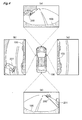
- Fig. 4 shows photographic images obtained by the respective cameras 11-13 in this situation.
- Fig. 4 (a) shows the photographic image obtained by the front camera 11 provided in the vehicle 100.
- the photographic image obtained by the front camera 11 includes the vehicle 200.
- Fig. 4 (b) shows the photographic image obtained by the left side camera 12a provided in the vehicle 100.
- the photographic image obtained by the left side camera 12a includes portions of the left wheels of the vehicle 100 and a portion of the vehicle 200.
- Fig. 4 (c) shows the photographic image obtained by the right side camera 12b provided in the vehicle 100.
- the photographic image obtained by the right side camera 12b includes portions of the right wheels of the vehicle 100.
- FIG. 4 (d) shows the photographic image obtained by the rear camera 13 provided in the vehicle 100.
- the photographic image obtained by the rear camera 13 includes the vehicle 201 and the vehicle 202.
- the photographic images as above are obtained by the respective cameras 11-13 and stored in the image acquisition unit 31.
- the immediate vicinities of the vehicle 100 become "blind comers". So, the confirmation of safety of the periphery of the vehicle 100 using these photographic images cannot be said to be perfect. That is, depending on the case, an obstacle such as a human or an object present in the periphery of the vehicle 100 might be overlooked.
- the confirmation of the far side of the vehicle 100 becomes impossible.
- the display device 41 is caused to display an image that can show not only the extreme vicinities of the vehicle 100, but also positions far from the vehicle 100.
- Fig. 5 shows such image.
- Fig. 5 shows an image with a viewing point set at a position perpendicularly upward of the vehicle 100 and this view is comprised of a fish-eye view. Namely, the image is formed such that the viewing point of the fish-eye image is a viewing point from the perpendicularly upper direction.
- This fish-eye image is generated by the fish-eye image generation unit 33 based upon the photographic images obtained by the respective cameras 11-13 and stored at the image acquisition unit 31.
- the fish-eye image shown in Fig. 5 includes the vehicle 200 and the vehicle 201 and includes also the extreme vicinities of the vehicle 100 as being visible therein. Further, as this is a fish-eye image, it includes also positions distant by certain extent from the vehicle 100. Therefore, it is possible for the user to confirm both the extreme vicinities of the vehicle 100 and the positions distant therefrom in a single image.
- the viewing point position of the fish-eye image can be changed. For instance, if the vehicle 100 is to be parked at a space available between the vehicle 201 and the vehicle 202 in the illustration shown on the left side of Fig. 6 , the fish-eye image generation unit 33 can generate the fish-eye image as shown on the right side in Fig. 6 to be displayed on the display device 41. With such appropriate change of the viewing position, it is possible for the user to observe the space between the vehicle 100 and the vehicle 201. Further, upon setting of a viewing position, there will be generated a self vehicle image showing the vehicle 100 in the form of a fish-eye image with the position set by the viewing point position setting unit 32 as the viewing point. Therefore, the visual confirmation of the periphery of the vehicle 100 can be made appropriately.
- the fish-eye image relating to the present invention may be generated through synthesis of photographic images obtained by the respective cameras 11-13. Further, needless to say, whether the lens of each camera 11-13 is a fish-eye lens or not, a top view image like a plan view may be generated, and these images may be rendered into a fish-eye image later.
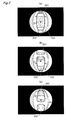
- the viewing point position of the fish-eye image can be changed by the user's operation on the viewing point changing switch 42.
- This viewing point changing switch may be configured to change the viewing point in a flexible manner in response to an operation of an input device such as a so-called "cross key".
- an input device such as a so-called "cross key”.
- FIG. 7 (b) it becomes possible to display a fish-eye image with the viewing point position being set forwardly and upwardly of the vehicle 100 (the perpendicularly upward of O in Fig. 7 (b) ).
- Fig. 7 (c) it becomes possible to display a fish-eye image with the viewing point position being set forwardly and upwardly of the vehicle 100 (the perpendicularly upward of O in Fig. 7 (c) ).
- a mode selection switch in order to allow selection and displaying of the viewing point position when desired or needed.
- this Fig. 7 there was explained the arrangement of the viewing point position being changeable within the horizontal plane normal to the perpendicular direction. Instead, the viewing point position may be made changeable along the perpendicular direction (height direction).
- the self vehicle image generation unit 35 may be configured to be generate the self vehicle image with its length reduced. With the generation of the self vehicle image in this manner, the resultant fish-eye image will allow even easier recognition of the forward and the rear sides of the vehicle 100.
- the viewing point of the fish-eye image is a viewing potion from the perpendicularly upward side.
- the applicable range of the present invention is not limited thereto.
- a fish-eye image is an image obtained when the image is obtained with using a so-called fish-eye lens, i.e. a convex type image.
- this can be generated by projecting and converting the periphery images of the vehicle 100 photographed by the plurality of photographic cameras 11-13 directly onto a convex face.
- the periphery images of the vehicle 100 photographed by the plurality of photographic cameras 11-13 may be projected and converted onto a flat plane and these are then combined and synthesized into a synthesized image (e.g. the so-called "top view image”) and then this synthesized image may be projected and converted onto a convex plane, thereby to generate the fish-eye image.
- the present invention is applicable to a vehicle periphery image generation apparatus for generating the vehicle periphery image that can command a wide view of the vehicle image at a time.
Landscapes
- Engineering & Computer Science (AREA)
- Multimedia (AREA)
- Mechanical Engineering (AREA)
- Signal Processing (AREA)
- Physics & Mathematics (AREA)
- General Physics & Mathematics (AREA)
- Theoretical Computer Science (AREA)
- Closed-Circuit Television Systems (AREA)
- Image Processing (AREA)
- Image Analysis (AREA)
- Fittings On The Vehicle Exterior For Carrying Loads, And Devices For Holding Or Mounting Articles (AREA)
Applications Claiming Priority (3)
| Application Number | Priority Date | Filing Date | Title |
|---|---|---|---|
| JP2009180561 | 2009-08-03 | ||
| JP2010163229A JP5500369B2 (ja) | 2009-08-03 | 2010-07-20 | 車両周辺画像生成装置 |
| PCT/JP2010/062658 WO2011016368A1 (ja) | 2009-08-03 | 2010-07-28 | 車両周辺画像生成装置 |
Publications (3)
| Publication Number | Publication Date |
|---|---|
| EP2464113A1 true EP2464113A1 (de) | 2012-06-13 |
| EP2464113A4 EP2464113A4 (de) | 2016-11-16 |
| EP2464113B1 EP2464113B1 (de) | 2019-12-04 |
Family
ID=43544264
Family Applications (1)
| Application Number | Title | Priority Date | Filing Date |
|---|---|---|---|
| EP10806367.8A Active EP2464113B1 (de) | 2009-08-03 | 2010-07-28 | Vorrichtung zur erstellung von fahrzeugumgebungsbildern |
Country Status (6)
| Country | Link |
|---|---|
| US (1) | US9156402B2 (de) |
| EP (1) | EP2464113B1 (de) |
| JP (1) | JP5500369B2 (de) |
| KR (1) | KR101354068B1 (de) |
| CN (1) | CN102474597B (de) |
| WO (1) | WO2011016368A1 (de) |
Cited By (6)
| Publication number | Priority date | Publication date | Assignee | Title |
|---|---|---|---|---|
| FR2994921A1 (fr) * | 2012-09-05 | 2014-03-07 | Peugeot Citroen Automobiles Sa | Dispositif de traitement pour generer un fichier d'image d'un environnement de vehicule selon une vue dont le type est fonction de la situation de vie, et systeme d'aide associe |
| EP3217352A4 (de) * | 2014-11-04 | 2017-11-15 | Denso Corporation | Fahrzeugumgebungsbildanzeigevorrichtung und fahrzeugumgebungsbildanzeigeverfahren |
| EP3202626A4 (de) * | 2014-09-29 | 2018-05-16 | Clarion Co., Ltd. | Fahrzeuginterne bildverarbeitungsvorrichtung |
| EP3340616A1 (de) * | 2016-12-21 | 2018-06-27 | Toyota Jidosha Kabushiki Kaisha | Fahrzeugumfeldüberwachungsvorrichtung |
| US10040394B2 (en) | 2015-06-17 | 2018-08-07 | Geo Semiconductor Inc. | Vehicle vision system |
| EP3550819A4 (de) * | 2016-11-30 | 2020-07-15 | KYOCERA Corporation | Kamera- und monitorsystem, bildverarbeitungsvorrichtung, fahrzeug und bildverarbeitungsverfahren |
Families Citing this family (33)
| Publication number | Priority date | Publication date | Assignee | Title |
|---|---|---|---|---|
| JP5935435B2 (ja) * | 2012-03-26 | 2016-06-15 | 富士通株式会社 | 画像処理装置、画像処理方法 |
| JP5629740B2 (ja) * | 2012-09-21 | 2014-11-26 | 株式会社小松製作所 | 作業車両用周辺監視システム及び作業車両 |
| JP6014442B2 (ja) * | 2012-09-27 | 2016-10-25 | 富士通テン株式会社 | 画像生成装置、画像表示システム、および、画像生成方法 |
| TWI578271B (zh) | 2012-10-23 | 2017-04-11 | 義晶科技股份有限公司 | 動態影像處理方法以及動態影像處理系統 |
| KR101382798B1 (ko) * | 2012-11-09 | 2014-04-08 | 현대자동차주식회사 | 차량의 카메라를 이용한 지도 생성 장치 및 방법 |
| WO2014085953A1 (en) * | 2012-12-03 | 2014-06-12 | Harman International Industries, Incorporated | System and method for detecting pedestrians using a single normal camera |
| US9674490B2 (en) * | 2013-04-18 | 2017-06-06 | Magna Electronics Inc. | Vision system for vehicle with adjustable cameras |
| CN103192785A (zh) * | 2013-04-25 | 2013-07-10 | 夏春蕾 | 车辆四周立体空间全监控系统 |
| JP6347934B2 (ja) * | 2013-10-11 | 2018-06-27 | 株式会社デンソーテン | 画像表示装置、画像表示システム、画像表示方法、及び、プログラム |
| CN103600707B (zh) * | 2013-11-06 | 2016-08-17 | 同济大学 | 一种智能泊车系统的泊车位检测装置及方法 |
| JP6307859B2 (ja) * | 2013-12-02 | 2018-04-11 | 日産自動車株式会社 | 情報表示装置 |
| US9598012B2 (en) * | 2014-03-11 | 2017-03-21 | Toyota Motor Engineering & Manufacturing North America, Inc. | Surroundings monitoring system for a vehicle |
| EP3154024B1 (de) * | 2014-06-03 | 2023-08-09 | Sumitomo Heavy Industries, Ltd. | Personendetektionssystem für eine baumaschine |
| CN104290661A (zh) * | 2014-09-18 | 2015-01-21 | 昆明理工大学 | 一种空中障碍物示警装置及其控制方法 |
| JP6361415B2 (ja) * | 2014-09-24 | 2018-07-25 | 株式会社デンソー | 車両用画像処理装置 |
| JP6555056B2 (ja) * | 2015-09-30 | 2019-08-07 | アイシン精機株式会社 | 周辺監視装置 |
| US9787951B2 (en) * | 2015-12-18 | 2017-10-10 | Serge Kannon | Vehicle proximity warning system |
| WO2017154317A1 (ja) * | 2016-03-09 | 2017-09-14 | 株式会社Jvcケンウッド | 車両用表示制御装置、車両用表示システム、車両用表示制御方法およびプログラム |
| JP6477562B2 (ja) * | 2016-03-18 | 2019-03-06 | 株式会社デンソー | 情報処理装置 |
| JP6699370B2 (ja) * | 2016-06-06 | 2020-05-27 | アイシン精機株式会社 | 車両用画像処理装置 |
| JP6730612B2 (ja) * | 2017-02-27 | 2020-07-29 | 株式会社Jvcケンウッド | 車両用表示制御装置、車両用表示制御システム、車両用表示制御方法およびプログラム |
| CN109455140B (zh) * | 2017-09-06 | 2022-03-01 | 丰田自动车株式会社 | 图像显示装置 |
| WO2019080051A1 (en) | 2017-10-26 | 2019-05-02 | Harman International Industries, Incorporated | PERIPHERAL VISION SYSTEM AND ASSOCIATED METHOD |
| JP7069692B2 (ja) * | 2017-12-20 | 2022-05-18 | トヨタ自動車株式会社 | 画像表示装置 |
| US10482626B2 (en) * | 2018-01-08 | 2019-11-19 | Mediatek Inc. | Around view monitoring systems for vehicle and calibration methods for calibrating image capture devices of an around view monitoring system using the same |
| US20200282909A1 (en) * | 2019-03-07 | 2020-09-10 | GM Global Technology Operations LLC | Vehicle imaging system and method for a parking solution |
| KR102140526B1 (ko) * | 2019-04-26 | 2020-08-04 | 주식회사 켐트로닉스 | 어라운드 뷰 장치 |
| JP7065068B2 (ja) * | 2019-12-13 | 2022-05-11 | 本田技研工業株式会社 | 車両周囲監視装置、車両、車両周囲監視方法およびプログラム |
| CN111445534B (zh) * | 2020-04-03 | 2023-04-21 | 北京四维智联科技有限公司 | 一种用于全自动泊车的相机高精度自动标定方法及装置 |
| JP7659425B2 (ja) * | 2021-03-25 | 2025-04-09 | 本田技研工業株式会社 | 制御装置、制御装置の動作方法及びプログラム |
| US20230087119A1 (en) * | 2021-09-22 | 2023-03-23 | Motional Ad Llc | Switchable wheel view mirrors |
| JP2024044213A (ja) | 2022-09-20 | 2024-04-02 | トヨタ自動車株式会社 | 車両用表示制御装置 |
| KR102524355B1 (ko) | 2022-10-14 | 2023-04-21 | 주식회사 옵티멀이노베이션 | Led 갈매기 표지판 |
Family Cites Families (20)
| Publication number | Priority date | Publication date | Assignee | Title |
|---|---|---|---|---|
| JP3475507B2 (ja) | 1994-08-08 | 2003-12-08 | 日産自動車株式会社 | 車両用周囲モニタ装置 |
| EP2267656A3 (de) * | 1998-07-31 | 2012-09-26 | Panasonic Corporation | Bildanzeigevorrichtung und Bildanzeigeverfahren |
| EP1179958B1 (de) * | 1999-04-16 | 2012-08-08 | Panasonic Corporation | Bildverarbeitungsgerät und überwachungssystem |
| JP3803021B2 (ja) * | 2000-10-02 | 2006-08-02 | 松下電器産業株式会社 | 運転支援装置 |
| JP3847547B2 (ja) | 2000-10-17 | 2006-11-22 | 三菱電機株式会社 | 車両周辺監視支援装置 |
| JP2002334322A (ja) * | 2001-05-10 | 2002-11-22 | Sharp Corp | 透視投影画像生成システム、透視投影画像生成方法、透視投影画像生成プログラムおよび透視投影画像生成プログラムを記憶した記憶媒体 |
| JP4071463B2 (ja) | 2001-07-16 | 2008-04-02 | 株式会社デンソー | 車両周辺画像処理装置 |
| US7212653B2 (en) * | 2001-12-12 | 2007-05-01 | Kabushikikaisha Equos Research | Image processing system for vehicle |
| JP2003346189A (ja) | 2002-05-24 | 2003-12-05 | Nissan Motor Co Ltd | 車両用映像表示装置 |
| JP2005167309A (ja) * | 2003-11-28 | 2005-06-23 | Nippon Soken Inc | 運転支援装置 |
| JP4134939B2 (ja) * | 2004-04-22 | 2008-08-20 | 株式会社デンソー | 車両周辺表示制御装置 |
| JP4744823B2 (ja) * | 2004-08-05 | 2011-08-10 | 株式会社東芝 | 周辺監視装置および俯瞰画像表示方法 |
| JP4600760B2 (ja) * | 2005-06-27 | 2010-12-15 | アイシン精機株式会社 | 障害物検出装置 |
| JP4939828B2 (ja) * | 2006-03-29 | 2012-05-30 | 株式会社デンソー | 画像処理装置及びプログラム |
| JP5045172B2 (ja) * | 2007-03-20 | 2012-10-10 | マツダ株式会社 | 車両用運転支援装置 |
| JP4458138B2 (ja) * | 2007-09-18 | 2010-04-28 | 株式会社デンソー | 車両周辺監視装置 |
| JP5120880B2 (ja) * | 2007-10-15 | 2013-01-16 | アルパイン株式会社 | 画像処理装置及び画像処理方法 |
| JP2009100261A (ja) * | 2007-10-17 | 2009-05-07 | Alpine Electronics Inc | 車両周囲画像提供装置及び広角画像の補正方法 |
| JP5292874B2 (ja) | 2007-12-17 | 2013-09-18 | 富士通株式会社 | 車両用画像処理装置、車両用画像処理プログラム、車両用画像処理方法 |
| DE102008046544A1 (de) * | 2008-09-10 | 2009-05-20 | Daimler Ag | Verfahren und Vorrichtung zur Überwachung einer Umgebung eines Fahrzeuges |
-
2010
- 2010-07-20 JP JP2010163229A patent/JP5500369B2/ja active Active
- 2010-07-28 EP EP10806367.8A patent/EP2464113B1/de active Active
- 2010-07-28 CN CN201080034684.7A patent/CN102474597B/zh not_active Expired - Fee Related
- 2010-07-28 KR KR1020127003991A patent/KR101354068B1/ko not_active Expired - Fee Related
- 2010-07-28 US US13/388,619 patent/US9156402B2/en active Active
- 2010-07-28 WO PCT/JP2010/062658 patent/WO2011016368A1/ja not_active Ceased
Non-Patent Citations (1)
| Title |
|---|
| See references of WO2011016368A1 * |
Cited By (8)
| Publication number | Priority date | Publication date | Assignee | Title |
|---|---|---|---|---|
| FR2994921A1 (fr) * | 2012-09-05 | 2014-03-07 | Peugeot Citroen Automobiles Sa | Dispositif de traitement pour generer un fichier d'image d'un environnement de vehicule selon une vue dont le type est fonction de la situation de vie, et systeme d'aide associe |
| EP3202626A4 (de) * | 2014-09-29 | 2018-05-16 | Clarion Co., Ltd. | Fahrzeuginterne bildverarbeitungsvorrichtung |
| EP3217352A4 (de) * | 2014-11-04 | 2017-11-15 | Denso Corporation | Fahrzeugumgebungsbildanzeigevorrichtung und fahrzeugumgebungsbildanzeigeverfahren |
| US10040394B2 (en) | 2015-06-17 | 2018-08-07 | Geo Semiconductor Inc. | Vehicle vision system |
| US10137836B2 (en) | 2015-06-17 | 2018-11-27 | Geo Semiconductor Inc. | Vehicle vision system |
| EP3550819A4 (de) * | 2016-11-30 | 2020-07-15 | KYOCERA Corporation | Kamera- und monitorsystem, bildverarbeitungsvorrichtung, fahrzeug und bildverarbeitungsverfahren |
| EP3340616A1 (de) * | 2016-12-21 | 2018-06-27 | Toyota Jidosha Kabushiki Kaisha | Fahrzeugumfeldüberwachungsvorrichtung |
| US10882450B2 (en) | 2016-12-21 | 2021-01-05 | Toyota Jidosha Kabushiki Kaisha | Vehicle periphery monitoring apparatus |
Also Published As
| Publication number | Publication date |
|---|---|
| WO2011016368A1 (ja) | 2011-02-10 |
| JP2011055480A (ja) | 2011-03-17 |
| KR101354068B1 (ko) | 2014-01-22 |
| US20120127312A1 (en) | 2012-05-24 |
| US9156402B2 (en) | 2015-10-13 |
| CN102474597B (zh) | 2015-01-21 |
| EP2464113A4 (de) | 2016-11-16 |
| EP2464113B1 (de) | 2019-12-04 |
| JP5500369B2 (ja) | 2014-05-21 |
| CN102474597A (zh) | 2012-05-23 |
| KR20120030162A (ko) | 2012-03-27 |
Similar Documents
| Publication | Publication Date | Title |
|---|---|---|
| US9156402B2 (en) | Wide view vehicle periphery image generation apparatus | |
| US9706175B2 (en) | Image processing device, image processing system, and image processing method | |
| EP2487906B1 (de) | Steuervorrichtung und umgebungsüberwachungsvorrichtung für ein fahrzeug | |
| JP5099451B2 (ja) | 車両周辺確認装置 | |
| JP3947375B2 (ja) | 駐車補助装置 | |
| US8031225B2 (en) | Surroundings monitoring system for a vehicle | |
| CN105073499B (zh) | 图像显示控制装置、图像显示系统及显示单元 | |
| CN102740056B (zh) | 图像显示系统 | |
| CN102632840B (zh) | 车辆周围监测装置 | |
| EP2763407A1 (de) | Vorrichtung zur überwachung von fahrzeugumgebungen | |
| US20120249796A1 (en) | Image processing device, image processing system, and image processing method | |
| CN102812703A (zh) | 图像显示装置 | |
| CN101631695A (zh) | 驻车辅助装置 | |
| WO2009151053A1 (ja) | 駐車支援装置及び駐車支援方法 | |
| CN103692973A (zh) | 图像生成装置、图像显示系统、以及图像生成方法 | |
| JP2010215027A (ja) | 車両用運転支援装置 | |
| JP2007221200A (ja) | 車両周辺監視装置 | |
| CN110831803B (zh) | 用于操作车辆操作系统的方法、设备和计算机程序 | |
| JP2012001126A (ja) | 車両用周辺監視装置 | |
| JP2007102691A (ja) | 車両用視界支援装置 | |
| JP5584561B2 (ja) | 画像処理装置、画像表示システム及び画像表示方法 | |
| JP2012046124A (ja) | 画像表示システム、画像処理装置、および、画像表示方法 | |
| KR102005551B1 (ko) | 주차 보조 시스템 | |
| JP5077286B2 (ja) | 車両周辺画像表示装置 | |
| KR102125738B1 (ko) | 주차 보조 시스템 |
Legal Events
| Date | Code | Title | Description |
|---|---|---|---|
| PUAI | Public reference made under article 153(3) epc to a published international application that has entered the european phase |
Free format text: ORIGINAL CODE: 0009012 |
|
| 17P | Request for examination filed |
Effective date: 20120119 |
|
| AK | Designated contracting states |
Kind code of ref document: A1 Designated state(s): AL AT BE BG CH CY CZ DE DK EE ES FI FR GB GR HR HU IE IS IT LI LT LU LV MC MK MT NL NO PL PT RO SE SI SK SM TR |
|
| DAX | Request for extension of the european patent (deleted) | ||
| REG | Reference to a national code |
Ref country code: DE Ref legal event code: R079 Ref document number: 602010062266 Country of ref document: DE Free format text: PREVIOUS MAIN CLASS: H04N0007180000 Ipc: G06T0003000000 |
|
| RA4 | Supplementary search report drawn up and despatched (corrected) |
Effective date: 20161018 |
|
| RIC1 | Information provided on ipc code assigned before grant |
Ipc: H04N 7/18 20060101ALI20161012BHEP Ipc: G06T 3/00 20060101AFI20161012BHEP Ipc: B60R 1/00 20060101ALI20161012BHEP |
|
| GRAJ | Information related to disapproval of communication of intention to grant by the applicant or resumption of examination proceedings by the epo deleted |
Free format text: ORIGINAL CODE: EPIDOSDIGR1 |
|
| STAA | Information on the status of an ep patent application or granted ep patent |
Free format text: STATUS: GRANT OF PATENT IS INTENDED |
|
| GRAP | Despatch of communication of intention to grant a patent |
Free format text: ORIGINAL CODE: EPIDOSNIGR1 |
|
| INTG | Intention to grant announced |
Effective date: 20190621 |
|
| GRAS | Grant fee paid |
Free format text: ORIGINAL CODE: EPIDOSNIGR3 |
|
| GRAA | (expected) grant |
Free format text: ORIGINAL CODE: 0009210 |
|
| STAA | Information on the status of an ep patent application or granted ep patent |
Free format text: STATUS: THE PATENT HAS BEEN GRANTED |
|
| AK | Designated contracting states |
Kind code of ref document: B1 Designated state(s): AL AT BE BG CH CY CZ DE DK EE ES FI FR GB GR HR HU IE IS IT LI LT LU LV MC MK MT NL NO PL PT RO SE SI SK SM TR |
|
| REG | Reference to a national code |
Ref country code: GB Ref legal event code: FG4D |
|
| RIN1 | Information on inventor provided before grant (corrected) |
Inventor name: WATANABE, KAZUYA Inventor name: KADOWAKI, JUN Inventor name: OOSHITA, YUUICHI Inventor name: NAGAMINE, NOBORU Inventor name: MATSUBA, TOMOYUKI Inventor name: MORI, TOSHIHIRO |
|
| REG | Reference to a national code |
Ref country code: CH Ref legal event code: EP |
|
| REG | Reference to a national code |
Ref country code: AT Ref legal event code: REF Ref document number: 1210323 Country of ref document: AT Kind code of ref document: T Effective date: 20191215 |
|
| REG | Reference to a national code |
Ref country code: DE Ref legal event code: R096 Ref document number: 602010062266 Country of ref document: DE |
|
| REG | Reference to a national code |
Ref country code: IE Ref legal event code: FG4D |
|
| REG | Reference to a national code |
Ref country code: NL Ref legal event code: MP Effective date: 20191204 |
|
| REG | Reference to a national code |
Ref country code: LT Ref legal event code: MG4D |
|
| PG25 | Lapsed in a contracting state [announced via postgrant information from national office to epo] |
Ref country code: ES Free format text: LAPSE BECAUSE OF FAILURE TO SUBMIT A TRANSLATION OF THE DESCRIPTION OR TO PAY THE FEE WITHIN THE PRESCRIBED TIME-LIMIT Effective date: 20191204 Ref country code: LV Free format text: LAPSE BECAUSE OF FAILURE TO SUBMIT A TRANSLATION OF THE DESCRIPTION OR TO PAY THE FEE WITHIN THE PRESCRIBED TIME-LIMIT Effective date: 20191204 Ref country code: SE Free format text: LAPSE BECAUSE OF FAILURE TO SUBMIT A TRANSLATION OF THE DESCRIPTION OR TO PAY THE FEE WITHIN THE PRESCRIBED TIME-LIMIT Effective date: 20191204 Ref country code: FI Free format text: LAPSE BECAUSE OF FAILURE TO SUBMIT A TRANSLATION OF THE DESCRIPTION OR TO PAY THE FEE WITHIN THE PRESCRIBED TIME-LIMIT Effective date: 20191204 Ref country code: BG Free format text: LAPSE BECAUSE OF FAILURE TO SUBMIT A TRANSLATION OF THE DESCRIPTION OR TO PAY THE FEE WITHIN THE PRESCRIBED TIME-LIMIT Effective date: 20200304 Ref country code: GR Free format text: LAPSE BECAUSE OF FAILURE TO SUBMIT A TRANSLATION OF THE DESCRIPTION OR TO PAY THE FEE WITHIN THE PRESCRIBED TIME-LIMIT Effective date: 20200305 Ref country code: NO Free format text: LAPSE BECAUSE OF FAILURE TO SUBMIT A TRANSLATION OF THE DESCRIPTION OR TO PAY THE FEE WITHIN THE PRESCRIBED TIME-LIMIT Effective date: 20200304 Ref country code: LT Free format text: LAPSE BECAUSE OF FAILURE TO SUBMIT A TRANSLATION OF THE DESCRIPTION OR TO PAY THE FEE WITHIN THE PRESCRIBED TIME-LIMIT Effective date: 20191204 |
|
| PG25 | Lapsed in a contracting state [announced via postgrant information from national office to epo] |
Ref country code: HR Free format text: LAPSE BECAUSE OF FAILURE TO SUBMIT A TRANSLATION OF THE DESCRIPTION OR TO PAY THE FEE WITHIN THE PRESCRIBED TIME-LIMIT Effective date: 20191204 |
|
| PG25 | Lapsed in a contracting state [announced via postgrant information from national office to epo] |
Ref country code: AL Free format text: LAPSE BECAUSE OF FAILURE TO SUBMIT A TRANSLATION OF THE DESCRIPTION OR TO PAY THE FEE WITHIN THE PRESCRIBED TIME-LIMIT Effective date: 20191204 |
|
| PG25 | Lapsed in a contracting state [announced via postgrant information from national office to epo] |
Ref country code: EE Free format text: LAPSE BECAUSE OF FAILURE TO SUBMIT A TRANSLATION OF THE DESCRIPTION OR TO PAY THE FEE WITHIN THE PRESCRIBED TIME-LIMIT Effective date: 20191204 Ref country code: NL Free format text: LAPSE BECAUSE OF FAILURE TO SUBMIT A TRANSLATION OF THE DESCRIPTION OR TO PAY THE FEE WITHIN THE PRESCRIBED TIME-LIMIT Effective date: 20191204 Ref country code: CZ Free format text: LAPSE BECAUSE OF FAILURE TO SUBMIT A TRANSLATION OF THE DESCRIPTION OR TO PAY THE FEE WITHIN THE PRESCRIBED TIME-LIMIT Effective date: 20191204 Ref country code: RO Free format text: LAPSE BECAUSE OF FAILURE TO SUBMIT A TRANSLATION OF THE DESCRIPTION OR TO PAY THE FEE WITHIN THE PRESCRIBED TIME-LIMIT Effective date: 20191204 Ref country code: PT Free format text: LAPSE BECAUSE OF FAILURE TO SUBMIT A TRANSLATION OF THE DESCRIPTION OR TO PAY THE FEE WITHIN THE PRESCRIBED TIME-LIMIT Effective date: 20200429 |
|
| PGFP | Annual fee paid to national office [announced via postgrant information from national office to epo] |
Ref country code: FR Payment date: 20200612 Year of fee payment: 11 |
|
| PG25 | Lapsed in a contracting state [announced via postgrant information from national office to epo] |
Ref country code: SM Free format text: LAPSE BECAUSE OF FAILURE TO SUBMIT A TRANSLATION OF THE DESCRIPTION OR TO PAY THE FEE WITHIN THE PRESCRIBED TIME-LIMIT Effective date: 20191204 Ref country code: IS Free format text: LAPSE BECAUSE OF FAILURE TO SUBMIT A TRANSLATION OF THE DESCRIPTION OR TO PAY THE FEE WITHIN THE PRESCRIBED TIME-LIMIT Effective date: 20200404 Ref country code: SK Free format text: LAPSE BECAUSE OF FAILURE TO SUBMIT A TRANSLATION OF THE DESCRIPTION OR TO PAY THE FEE WITHIN THE PRESCRIBED TIME-LIMIT Effective date: 20191204 |
|
| REG | Reference to a national code |
Ref country code: DE Ref legal event code: R097 Ref document number: 602010062266 Country of ref document: DE |
|
| REG | Reference to a national code |
Ref country code: AT Ref legal event code: MK05 Ref document number: 1210323 Country of ref document: AT Kind code of ref document: T Effective date: 20191204 |
|
| PLBE | No opposition filed within time limit |
Free format text: ORIGINAL CODE: 0009261 |
|
| STAA | Information on the status of an ep patent application or granted ep patent |
Free format text: STATUS: NO OPPOSITION FILED WITHIN TIME LIMIT |
|
| PG25 | Lapsed in a contracting state [announced via postgrant information from national office to epo] |
Ref country code: DK Free format text: LAPSE BECAUSE OF FAILURE TO SUBMIT A TRANSLATION OF THE DESCRIPTION OR TO PAY THE FEE WITHIN THE PRESCRIBED TIME-LIMIT Effective date: 20191204 |
|
| 26N | No opposition filed |
Effective date: 20200907 |
|
| PG25 | Lapsed in a contracting state [announced via postgrant information from national office to epo] |
Ref country code: SI Free format text: LAPSE BECAUSE OF FAILURE TO SUBMIT A TRANSLATION OF THE DESCRIPTION OR TO PAY THE FEE WITHIN THE PRESCRIBED TIME-LIMIT Effective date: 20191204 Ref country code: AT Free format text: LAPSE BECAUSE OF FAILURE TO SUBMIT A TRANSLATION OF THE DESCRIPTION OR TO PAY THE FEE WITHIN THE PRESCRIBED TIME-LIMIT Effective date: 20191204 Ref country code: PL Free format text: LAPSE BECAUSE OF FAILURE TO SUBMIT A TRANSLATION OF THE DESCRIPTION OR TO PAY THE FEE WITHIN THE PRESCRIBED TIME-LIMIT Effective date: 20191204 |
|
| PG25 | Lapsed in a contracting state [announced via postgrant information from national office to epo] |
Ref country code: IT Free format text: LAPSE BECAUSE OF FAILURE TO SUBMIT A TRANSLATION OF THE DESCRIPTION OR TO PAY THE FEE WITHIN THE PRESCRIBED TIME-LIMIT Effective date: 20191204 |
|
| PG25 | Lapsed in a contracting state [announced via postgrant information from national office to epo] |
Ref country code: MC Free format text: LAPSE BECAUSE OF FAILURE TO SUBMIT A TRANSLATION OF THE DESCRIPTION OR TO PAY THE FEE WITHIN THE PRESCRIBED TIME-LIMIT Effective date: 20191204 |
|
| REG | Reference to a national code |
Ref country code: CH Ref legal event code: PL |
|
| GBPC | Gb: european patent ceased through non-payment of renewal fee |
Effective date: 20200728 |
|
| REG | Reference to a national code |
Ref country code: BE Ref legal event code: MM Effective date: 20200731 |
|
| PG25 | Lapsed in a contracting state [announced via postgrant information from national office to epo] |
Ref country code: CH Free format text: LAPSE BECAUSE OF NON-PAYMENT OF DUE FEES Effective date: 20200731 Ref country code: LI Free format text: LAPSE BECAUSE OF NON-PAYMENT OF DUE FEES Effective date: 20200731 Ref country code: GB Free format text: LAPSE BECAUSE OF NON-PAYMENT OF DUE FEES Effective date: 20200728 Ref country code: LU Free format text: LAPSE BECAUSE OF NON-PAYMENT OF DUE FEES Effective date: 20200728 |
|
| PG25 | Lapsed in a contracting state [announced via postgrant information from national office to epo] |
Ref country code: BE Free format text: LAPSE BECAUSE OF NON-PAYMENT OF DUE FEES Effective date: 20200731 |
|
| PG25 | Lapsed in a contracting state [announced via postgrant information from national office to epo] |
Ref country code: IE Free format text: LAPSE BECAUSE OF NON-PAYMENT OF DUE FEES Effective date: 20200728 |
|
| PG25 | Lapsed in a contracting state [announced via postgrant information from national office to epo] |
Ref country code: TR Free format text: LAPSE BECAUSE OF FAILURE TO SUBMIT A TRANSLATION OF THE DESCRIPTION OR TO PAY THE FEE WITHIN THE PRESCRIBED TIME-LIMIT Effective date: 20191204 Ref country code: MT Free format text: LAPSE BECAUSE OF FAILURE TO SUBMIT A TRANSLATION OF THE DESCRIPTION OR TO PAY THE FEE WITHIN THE PRESCRIBED TIME-LIMIT Effective date: 20191204 Ref country code: FR Free format text: LAPSE BECAUSE OF NON-PAYMENT OF DUE FEES Effective date: 20210731 Ref country code: CY Free format text: LAPSE BECAUSE OF FAILURE TO SUBMIT A TRANSLATION OF THE DESCRIPTION OR TO PAY THE FEE WITHIN THE PRESCRIBED TIME-LIMIT Effective date: 20191204 |
|
| PG25 | Lapsed in a contracting state [announced via postgrant information from national office to epo] |
Ref country code: MK Free format text: LAPSE BECAUSE OF FAILURE TO SUBMIT A TRANSLATION OF THE DESCRIPTION OR TO PAY THE FEE WITHIN THE PRESCRIBED TIME-LIMIT Effective date: 20191204 |
|
| PGFP | Annual fee paid to national office [announced via postgrant information from national office to epo] |
Ref country code: DE Payment date: 20250604 Year of fee payment: 16 |