EP2464163A1 - Verfahren, vorrichtung und benutzergerät zur konfiguration von referenzsignalen - Google Patents
Verfahren, vorrichtung und benutzergerät zur konfiguration von referenzsignalen Download PDFInfo
- Publication number
- EP2464163A1 EP2464163A1 EP10806052A EP10806052A EP2464163A1 EP 2464163 A1 EP2464163 A1 EP 2464163A1 EP 10806052 A EP10806052 A EP 10806052A EP 10806052 A EP10806052 A EP 10806052A EP 2464163 A1 EP2464163 A1 EP 2464163A1
- Authority
- EP
- European Patent Office
- Prior art keywords
- reference signal
- information
- group number
- uem
- number information
- Prior art date
- Legal status (The legal status is an assumption and is not a legal conclusion. Google has not performed a legal analysis and makes no representation as to the accuracy of the status listed.)
- Granted
Links
Images


Classifications
-
- H—ELECTRICITY
- H04—ELECTRIC COMMUNICATION TECHNIQUE
- H04L—TRANSMISSION OF DIGITAL INFORMATION, e.g. TELEGRAPHIC COMMUNICATION
- H04L5/00—Arrangements affording multiple use of the transmission path
- H04L5/003—Arrangements for allocating sub-channels of the transmission path
- H04L5/0048—Allocation of pilot signals, i.e. of signals known to the receiver
- H04L5/005—Allocation of pilot signals, i.e. of signals known to the receiver of common pilots, i.e. pilots destined for multiple users or terminals
-
- H—ELECTRICITY
- H04—ELECTRIC COMMUNICATION TECHNIQUE
- H04L—TRANSMISSION OF DIGITAL INFORMATION, e.g. TELEGRAPHIC COMMUNICATION
- H04L5/00—Arrangements affording multiple use of the transmission path
- H04L5/003—Arrangements for allocating sub-channels of the transmission path
- H04L5/0032—Distributed allocation, i.e. involving a plurality of allocating devices, each making partial allocation
- H04L5/0035—Resource allocation in a cooperative multipoint environment
-
- H—ELECTRICITY
- H04—ELECTRIC COMMUNICATION TECHNIQUE
- H04L—TRANSMISSION OF DIGITAL INFORMATION, e.g. TELEGRAPHIC COMMUNICATION
- H04L5/00—Arrangements affording multiple use of the transmission path
- H04L5/003—Arrangements for allocating sub-channels of the transmission path
- H04L5/0058—Allocation criteria
- H04L5/0064—Rate requirement of the data, e.g. scalable bandwidth, data priority
-
- H—ELECTRICITY
- H04—ELECTRIC COMMUNICATION TECHNIQUE
- H04L—TRANSMISSION OF DIGITAL INFORMATION, e.g. TELEGRAPHIC COMMUNICATION
- H04L5/00—Arrangements affording multiple use of the transmission path
- H04L5/0091—Signalling for the administration of the divided path, e.g. signalling of configuration information
- H04L5/0092—Indication of how the channel is divided
-
- H—ELECTRICITY
- H04—ELECTRIC COMMUNICATION TECHNIQUE
- H04W—WIRELESS COMMUNICATION NETWORKS
- H04W24/00—Supervisory, monitoring or testing arrangements
- H04W24/02—Arrangements for optimising operational condition
-
- H—ELECTRICITY
- H04—ELECTRIC COMMUNICATION TECHNIQUE
- H04W—WIRELESS COMMUNICATION NETWORKS
- H04W4/00—Services specially adapted for wireless communication networks; Facilities therefor
- H04W4/06—Selective distribution of broadcast services, e.g. multimedia broadcast multicast service [MBMS]; Services to user groups; One-way selective calling services
- H04W4/08—User group management
-
- H—ELECTRICITY
- H04—ELECTRIC COMMUNICATION TECHNIQUE
- H04W—WIRELESS COMMUNICATION NETWORKS
- H04W48/00—Access restriction; Network selection; Access point selection
- H04W48/08—Access restriction or access information delivery, e.g. discovery data delivery
-
- H—ELECTRICITY
- H04—ELECTRIC COMMUNICATION TECHNIQUE
- H04W—WIRELESS COMMUNICATION NETWORKS
- H04W48/00—Access restriction; Network selection; Access point selection
- H04W48/16—Discovering, processing access restriction or access information
Definitions
- the present invention relates to the field of communications technologies, and in particular, to a method, a device and a user equipment for configuring a reference signal.
- a reference signal (Reference Signal, RS for short) is generally formed by performing modulation with a certain sequence actually known by a sender and a receiver. After the sender sends the reference signal, the receiver receives according to the actually known sequence, so as to obtain channel situation in a corresponding time period, at a corresponding frequency, or on corresponding antenna resources.
- a sounding reference signal Sounding Reference Signal, SRS for short
- an evolved Node B evolved Node B, eNB
- eNB evolved Node B
- the eNB In order to enable the eNB to perform uplink scheduling reasonably, the eNB needs to obtain uplink broadband channel information of the user equipment (User Equipment, UE for short), and the uplink broadband channel information needs to be acquired through the SRS of the UE. Specifically, the eNB schedules a resource of the SRS for the user equipment UE, the UE sends the SRS through the resource, and the eNB performs detection after receiving the SRS sent by the UE, so as to obtain the uplink broadband channel information. Generally, the UE is served by only one cell, and the eNB may enable the SRS of the UE in the cell to be orthogonal to SRSs of other UEs in this cell through scheduling, thereby ensuring preferable detecting performance of the SRS.
- the eNB may enable the SRS of the UE in the cell to be orthogonal to SRSs of other UEs in this cell through scheduling, thereby ensuring preferable detecting performance of the SRS.
- a coordinated multi-point (Coordinated Multi-Point, CoMP for short) transmission technology is introduced, so that the UE may be served by multiple cells, and in a CoMP system, the UE capable of being served by multiple cells is referred to as a (CoMP UE, UEm).
- CoMP UE, UEm the UE capable of being served by multiple cells
- On uplink a signal sent by the UEm may be received by detectors of multiple cells, so that the signal transmitted through uplink may acquire diversity gains among the multiple cells, thereby improving the system performance.
- Embodiments of the present invention aim to provide a method, a device and a user equipment for configuring a reference signal, so as to realize the configuration of RSs for UEms, and avoid interference generated by RSs of the UEms.
- An embodiment of the present invention provides a method for configuring a reference signal, which includes:
- An embodiment of the present invention further provides a method for configuring a reference signal, which includes:
- An embodiment of the present invention further provides a method for configuring a reference signal, which includes:
- An embodiment of the present invention further provides a method for configuring a reference signal, which includes:
- An embodiment of the present invention further provides a device for configuring a reference signal, which includes:
- An embodiment of the present invention further provides a device for configuring a reference signal, which includes:
- An embodiment of the present invention further provides a user equipment, which includes:
- An embodiment of the present invention further provides a user equipment, which includes:
- group number information of an RS allocated for a UE respectively by each cell is acquired; group offset information of the RS in the UE is acquired according to the group number information; and the group offset information is sent to a UEm, so that the UEm acquires new group number information according to the allocated group number information of the RS and the group offset information, and sends an RS according to the new group number information, thereby avoiding interference generated by the UE in each cell on a scheduled UEm when an eNB schedules the UEm.
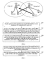
- FIG. 1 is a schematic structure diagram of a CoMP system
- FIG. 2 is a schematic flow chart of an embodiment of a method for configuring a reference signal of the present invention
- FIG. 3 is a schematic flow chart of another embodiment of a method for configuring a reference signal of the present invention.
- FIG. 4 is a schematic flow chart of still another embodiment of a method for configuring a reference signal of the present invention.
- FIG. 5 is a schematic flow chart of yet another embodiment of a method for configuring a reference signal of the present invention.
- FIG. 6 is a schematic structure diagram of an embodiment of a device for configuring a reference signal of the present invention.
- FIG. 7 is a schematic structure diagram of another embodiment of a device for configuring a reference signal of the present invention.
- FIG. 8 is a schematic structure diagram of an embodiment of a user equipment of the present invention.
- FIG. 9 is a schematic structure diagram of another embodiment of a user equipment of the present invention.
- FIG. 10 is a schematic structure diagram of an embodiment of a system for configuring a reference signal applicable to an embodiment of the present invention.
- FIG. 11 is a schematic structure diagram of another embodiment of a system for configuring a reference signal applicable to an embodiment of the present invention.
- the reference signal may be a signal modulated through a sequence, for example, a demodulation reference signal or a sounding reference signal.
- the demodulation reference signal may be used to demodulate data
- the sounding reference signal may be used to sound channel information.
- FIG. 1 is a schematic structure diagram of a CoMP system.
- a UE1 in a first cell and a UE3 in a second cell may be provided with services by an eNB1 and an eNB2 at the same time, and belong to CoMP UEs (UEm) in the CoMP system.
- a UE2 in the first cell can only be provided with services by the eNB1, and a UE4 in the second cell can only be provided with services by the eNB2, and therefore, the UE2 and the UE4 belong to common UEs.
- the eNB1 may prevent an RS of the UE1 from being interfered by the UE2 in the first cell.
- the eNB2 may be interfered when detecting the RS of the UE1, so that the eNB2 cannot obtain preferable detecting performance.
- the CoMP system shown in FIG. 1 is only a description, and the number of cells in the CoMP system in the embodiment of the present invention is not limited to the situation that is shown in FIG. 1 where totally two cells, that is, the first cell and the second cell, exist.
- the number of the first cell and the second cell in the embodiment of the present invention may be several according to actual situations, and the first cell and the second cell may be controlled by one eNB, or respectively controlled by two eNBs.
- Group number information mentioned in the embodiments of the present invention below may specifically refer to a group number of a group where a sequence adopted by the RS locates.
- the RS adopts constant amplitude zero auto correlation (Constant Amplitude Zero Auto Correlation, CAZAC for short) sequences, and M CAZAC sequences are divided into N groups (M is a number of all available CAZAC sequences, and N may be the number of the cells); and N group numbers exist in the N groups of CAZAC sequences.
- CAZAC Constant Amplitude Zero Auto Correlation
- the first cell serves the UE2 and the UE1
- the second cell serves the UE3 and the UE4, and in addition, the first cell and the second cell serve the UE1 and the UE3 at the same time, and the UE1 and the UE3 may be CoMP UEs.
- the first cell and the second cell have different identities (ID), so a group number u1 of the first cell is different from a group number u2 of the second cell.
- the UEms (UE1, UE3) in the first cell and in the second cell need to have the same group number.
- the following three manners may be used to enable all UEms in the first cell and the second cell to update respective group numbers, and enable the group numbers of the UEms to be the same.
- the new group number is formed by adding ⁇ to the group number of the UEm in the second cell.
- the UEm in the first cell and the UEm in the second cell form new group number information.
- the foregoing example only takes the UEm in the first cell being the UE1 and the UEm in the second cell being the UE3 as an example.
- the cells in the embodiment of the present invention are not limited to be two cells, and a UEm under multiple cells may be set during specific implementation, and the number of the UEm in each cell is not limited to be one, and multiple UEms may be set during specific implementation according to actual situations.
- a primary cell mentioned in the following embodiments of the present invention may be a serving cell having one function or all functions as follows: determining a parameter of uplink transmission of the UE, sending a signaling to the UE, and/or cooperatively processing an uplink signal of the UE.
- Other cells serving the UE are referred to as auxiliary cells of the UE.
- FIG. 2 is a schematic flow chart of an embodiment of a method for configuring a reference signal of the present invention. As shown in FIG. 2 , this embodiment includes the following steps:
- group number information of an RS allocated for a UE respectively by each cell is acquired; group offset information of the RS in the UE is acquired according to the group number information; and the group offset information is sent to a UEm, so that the UEm acquires new group number information according to the allocated group number information of the RS and the group offset information, and sends an RS according to the new group number information, thereby avoiding interference generated between the UEms in the cells on when an eNB schedules the UEm.
- the step 203 may further include:
- the group offset is sent to the UEm in each cell, so that the UEm acquires new group number information according to a sum of or a difference between the allocated group number information of the RS and the group offset, so that different UEms have the same group number information of the reference signal.
- illustration is made by taking two cells as an example, that is, a first cell and a second cell exist.
- the first cell has a group number being u1 and a group offset being ⁇ 1
- the second cell has a group number being u2 and a group offset being ⁇ 2.
- the group offset enabling information is set to the corresponding UEm in each cell, so that after receiving the group offset enabling information, the UEm acquires new group number information according to a sum of or a difference between the allocated group number information of the RS and the preset group offset, so that different UEms have the same group number information of the RS.
- the group offset enabling information may be sent to the UEm in each cell in advance through a downlink signaling.
- the UEm may be notified of the group offset information used by a physical uplink share channel (Physical Uplink Share Channel, PUSCH for short) through the downlink signaling.
- PUSCH Physical Uplink Share Channel
- the group offset enabling information may be notified to the UEm in each cell only through a signaling of 1 bit, thereby saving the signaling overhead. Moreover, the UEm in each cell acquires the same group number information of the RS according to the group offset enabling information, thereby avoiding the interference generated by the UE in each cell on a scheduled UEm when an eNB schedules the UEm.
- a modulus of N may be obtained for the group number corresponding to the group number information, thereby obtaining an available new group number.
- the new group number information is sent to the UEm in each cell, so that the UEm serves the allocated new group number information as the new group number information, and therefore, different UEms have the same group number information of the RS. Different UEms have the same group number information of the RS, thereby avoiding the interference generated by the UE in each cell on a scheduled UEm when an eNB schedules the UEm.
- the embodiment further includes:
- the embodiment further includes:
- the embodiment further includes:
- the UEm sends the RS in the intersection of the total sounding bandwidth or in the subset of the intersection of the total sounding bandwidth, so as to avoid interference caused by the RS of the UEm on other UEs of the auxiliary cell since the total sounding bandwidth of the UEm is greater than the total sounding bandwidth of the auxiliary cell.
- the embodiment when each cell is respectively controlled by a different eNB, the embodiment further includes: sharing, by different eNBs, emission parameters of the RSs allocated by the respective cells, where the emission parameter of the RS at least includes the allocated group number information, or the group offset information of the RS of the UEm. Different eNBs share the emission parameters of the RSs allocated by the respective cells.
- FIG. 3 is a schematic flow chart of another embodiment of a method for configuring a reference signal. As shown in FIG. 3 , this embodiment includes the following steps:
- the sending time allocated by each serving cell for the UE to send the RS is acquired, and the time intersection information of the allocated sending time is acquired, so that the UEm sends the RS in the time intersection or in a subset of the time intersection, thereby avoiding the interference generated by the UE in each cell on a scheduled UEm when an eNB schedules the UEm.
- the RS transmission time of the UEm of the primary cell is transmitting every transmission time interval (Transmission Time Interval, TTI for short)
- TTI Transmission Time Interval
- the RS total sounding bandwidth of the UEm in the auxiliary cell is transmitting every 2 TTIs
- the time intersection of the UEm in the primary cell and the UEm in the auxiliary cell is every 2 TTIs
- a subset of every 2 TTIs may be every 4 TTIs. Therefore, the RS transmission time of the UEm in the primary cell and the UEm in the auxiliary cell may be transmitting every 2 TTIs or every 4 TTIs.
- the embodiment further includes:
- the UEm sends the RS in the total sounding bandwidth intersection or in the subset of the total sounding bandwidth intersection, so as to avoid interference caused by the RS of the UEm on other UEs of the auxiliary cell since the total sounding bandwidth of the UEm is greater than the total sounding bandwidth of the auxiliary cell.
- the RS here may specifically refer to an SRS.
- FIG. 4 is a schematic flow chart of still another embodiment of a method for configuring a reference signal. As shown in FIG. 4 , this embodiment includes the following steps:
- the group offset information of the RS allocated by the base station is received; new group number information is acquired according to the group offset information and the allocated group number information of the RS; and an RS is sent according to the new group number information, thereby avoiding the interference generated by the UE in each cell on a scheduled UEm when an eNB schedules the UEm.
- the step 402 may specifically include:
- the step 403 may specifically include:
- FIG. 5 is a schematic flow chart of yet another embodiment of a method for configuring a reference signal. As shown in FIG. 5 , this embodiment includes the following steps:
- the time intersection information sent by the base station is received, and the UEm sends the RS in the time intersection or in a subset of the time intersection, thereby avoiding the interference generated by the UE in each cell on a scheduled UEm when an eNB schedules the UEm.
- the embodiment further includes:
- FIG. 6 is a schematic structure diagram of an embodiment of a device for configuring a reference signal of the present invention. As shown in FIG. 6 , this embodiment includes: a first acquiring module 61, a second acquiring module 62, and a first sending module 63.
- the first acquiring module 61 acquires group number information of a reference signal allocated for a user equipment UE respectively by each cell; the second acquiring module 62 acquires, according to the group number information acquired by the first acquiring module 61, group offset information of a reference signal of a user equipment UEm served by at least two cells at the same time in the UE, where the group offset information is used to update the group number information of the reference signal of the UEm; the first sending module 63 sends the group offset information acquired by the second acquiring module 62 to the UEm, so that the UEm acquires new group number information according to the allocated group number information of the reference signal and the group offset information, and sends a reference signal according to the new group number information.
- the first acquiring module 61 acquires group number information of an RS allocated for a UE respectively by each cel; the second acquiring module 62 acquires group offset information of the RS in the UE according to the group number information; the first sending module 63 sends the group offset information to the UEm, so that the UEm acquires new group number information according to the allocated group number information of the RS and the group offset information, and sends an RS according to the new group number information, thereby avoiding the interference generated by the UE in each cell on a scheduled UEm when an eNB schedules the UEm.
- this embodiment may further include: a first configuring module and/or a second configuring module.
- the first configuring module is configured to configure an emission parameter of the reference signal of the UE under each cell, so that the UEm and the UE that only is served by a primary cell of the UEm send the reference signals at different time points; or, the second configuring module is configured to configure an emission parameter of the reference signal of the UE under each cell, so that the UEm and the UE that only is served by a primary cell of the UEm send the reference signals at different combs.
- this embodiment may further include: a third acquiring module and a second sending module.
- the third acquiring module is configured to acquire sending time allocated by each cell providing services for the UEm for the UE to send the reference signal, and acquire time intersection information of the allocated sending time; and the second sending module, configured to send the time intersection information to the UEm, so that the UEm sends the reference signal in the time intersection or in a subset of the time intersection.
- this embodiment may further include: a fourth acquiring module and a third sending module.
- the fourth acquiring module is configured to acquire a total sounding bandwidth allocated by each cell providing services for the UEm for the UE to send the reference signal, and acquire total sounding bandwidth intersection information of the allocated total sounding bandwidth; and the third sending module, configured to send the intersection information of the total sounding bandwidth to the UEm, so that the UEm sends the reference signal in the total sounding bandwidth intersection or a subset of the total sounding bandwidth intersection.
- the RS here may specifically refer to an SRS.
- this embodiment may further include: a sharing module.
- the sharing module is configured to, when each cell is respectively controlled by a different evolved Node B eNB, enable the different eNBs to share emission parameters of reference signals allocated by the respective cells, where the emission parameter of the reference signal at least comprises the allocated group number information, or the group offset information of the reference signal of the UEm.
- FIG. 7 is a schematic structure diagram of another embodiment of a device for configuring a reference signal of the present invention. As shown in FIG. 7 , this embodiment includes: a fifth acquiring module 71 and a fourth sending module 72.
- the fifth acquiring module 71 acquires sending time allocated by each serving cell of a user equipment UEm served by at least two cells at the same time for a UE to send a reference signal, and acquires time intersection information of the allocated sending time; and the fourth sending module 72 sends the time intersection information acquired by the fifth acquiring module 71 to the UEm, so that the UEm sends the reference signal in the time intersection or in a subset of the time intersection.
- the fifth acquiring module 71 acquires the sending time allocated by each serving cell for the UE to send the RS, and acquires the time intersection information of the allocated sending time, so that the UEm sends the RS in the time intersection or in a subset of the time intersection, thereby avoiding the interference generated by the UE in each cell on a scheduled UEm when an eNB schedules the UEm.
- this embodiment may further include: a sixth acquiring module and a fifth sending module.
- the second acquiring module is configured to acquire a total sounding bandwidth allocated by each cell providing services for the UEm for the UE to send the reference signal, and acquire total sounding bandwidth intersection information of the allocated total sounding bandwidth; and the second sending module, configured to send the intersection information of the total sounding bandwidth to the UEm, so that the UEm sends the reference signal in the total sounding bandwidth intersection or a subset of the total sounding bandwidth intersection.
- the RS here may specifically refer to an SRS.
- FIG. 8 is a schematic structure diagram of an embodiment of a user equipment of the present invention. As shown in FIG. 8 , this embodiment includes: a first receiving module 81, a seventh acquiring module 82, and a sixth sending module 83.
- the first receiving module 81 receives group offset information of a reference signal allocated by a base station; the seventh acquiring module 82 acquires new group number information according to the group offset information received by the first receiving module 81 and the allocated group number information of the reference signal; and the sixth sending module 83 sends a reference signal according to the new group number information acquired by the seventh acquiring module 82.
- the first receiving module 81 receives the group offset information of the RS allocated by the base station; the seventh acquiring module 82 acquires new group number information according to the group offset information and the allocated group number information of the RS; and the sixth sending module 83 sends an RS according to the new group number information, thereby avoiding the interference generated by the UE in each cell on a scheduled UEm when an eNB schedules the UEm.
- the seventh acquiring module 82 may further include: a first acquiring unit, and/or a second acquiring unit, and/or a third acquiring unit.
- the first acquiring unit is configured to acquire new group number information according to a sum of or a difference between the allocated group number information of the reference signal and the group offset, so that the new group number information is the same as group number information of another user equipment UEm served by at least two cells at the same time;
- the second acquiring unit is configured to, after receiving the group offset enabling information, acquire new group number information according to a sum of or a difference between the allocated group number information of the reference signal and a preset group offset, so that the new group number information is the same as group number information of another user equipment UEm served by at least two cells at the same time;
- the third acquiring unit is configured to serve the allocated new group number information as new group number information, so that the new group number information is the same as group number information of another user equipment UEm served by at least two cells at the same time.
- the sixth sending module 82 may further include: a first sending unit, and/or a second sending unit.
- the first sending unit is configured to send the reference signal at a time point different from a UE only served by a primary cell thereof according to a configured emission parameter of the reference signal; and the second sending unit is configured to send the reference signal at a comb different from a UE only served by a primary cell thereof according to a configured emission parameter of the reference signal.
- FIG. 9 is a schematic structure diagram of another embodiment of a user equipment of the present invention. As shown in FIG. 9 , this embodiment includes: a second receiving module 91, and a seventh sending module 92.
- the second receiving module 91 receives time intersection information sent by a base station, where the time intersection information is time intersection information acquired by the base station according to sending time allocated by each serving cell of a user equipment UEm served by at least two cells at the same time for sending a reference signal to a UE; and the seventh sending module 92 sends a reference signal in the time intersection or in a subset of the time intersection received by the second receiving module 91.
- the second receiving module 91 receives the time intersection information sent by the base station, and the seventh sending module 92 sends the RS in the time intersection or in a subset of the time intersection, thereby avoiding the interference generated by the UE in each cell on a scheduled UEm when an eNB schedules the UEm.
- this embodiment may further include: a third receiving module and an eighth sending module.
- the third receiving module is configured to receive intersection information of total sounding bandwidth sent by a base station, where the total sounding bandwidth intersection information is total sounding bandwidth intersection information acquired by the base station according to the total sounding bandwidth allocated by each cell providing services for the UEm for a UE to send a reference signal; and the eighth sending module is configured to send a reference signal in the total sounding bandwidth intersection or in a subset of the total sounding bandwidth intersection.
- the RS here may specifically refer to an SRS.
- FIG. 10 is a schematic structure diagram of an embodiment of a system for configuring a reference signal applicable to an embodiment of the present invention.
- an eNB connects to a first cell and a second cell in a wired manner, and controls UEs in the first cell and the second cell.
- a UE1 is a UEm in the first cell that can be served by the first cell and the second cell;
- a UE2 is a UEm in the second cell that can be served by the first cell and the second cell;
- a UE3 is a common UE that can only be served by the first cell; and
- a UE4 is a common UE that can only be served by the second cell.
- the eNB control resource information of RSs of the first cell and the second cell at the same time, and therefore, RSs between the UE1, UE2, and other UEs (the UE3, UE4) may be coordinated directly through configuring parameters. Specifically, the foregoing description may be implemented through the following manner.
- the eNB acquires group number information of RSs of the UE (UE1) in the first cell and the UE (UE2) in the second cell, and acquires group offset information of the RS of the UEms (UE1, UE2) in the first cell and the second cell according to the group number information, so that the group number information of the RSs of the UE1 in the first cell and the UE2 in the second cell are the same as new group number information formed by the group offset information.
- the eNB sends the new group number information to the UE1 in the first cell and the UE2 in the second cell, so that the UE1 in the first cell and the UE2 in the second cell send RSs according to the new group number information.
- the UE1 and the UE2 that are served by the first cell and the second cell have the same new group number information, so that the UE1 and the UE2 that are served by the first cell and the second cell send the RSs according to the same new group number information, thereby avoiding the interference generated by the UE2 in the second cell on the scheduled UE1 when the eNB schedules the UE1 in the first cell.
- FIG. 11 is a schematic structure diagram of another embodiment of a system for configuring a reference signal applicable to an embodiment of the present invention.
- an eNB1 and an eNB2 are connected through a signaling interface between eNBs; the eNB1 is connected to a first cell in a wired manner; the eNB2 is connected to a second cell in a wired manner; the eNB1 controls UEs (UE1, UE3) in the first cell; and the eNB2 controls UEs (UE2, UE4) in the second cell.
- the UE1 is a UEm in the first cell that can be served by the first cell and the second cell; the UE2 is a UEm in the second cell that can be served by the first cell and the second cell; the UE3 is a common UE in the first cell; and the UE4 is a common UE in the second cell.
- the eNB1 controls resource information of RSs of the UEs in the first cell; the eNB2 controls resource information of RSs of the UEs in the second cell; and the eNB1 and the eNB2 are independent with each other, so the embodiment of the present invention enables the resource information of the RSs of the UEms to be orthogonal, thereby avoiding the interference generated between the RS of the UEm in the first cell under the eNB1 and the RS of the UEm in the second cell under the eNB2.
- the eNB1 acquires, through an interface, first configuration information of the RS of the UEm (UE2) in the second cell under the eNB2, acquires second configuration information of the RS of the UEm (UE1) in the first cell under the eNB1, and sends the second configuration information to the UE1 under the eNB1, so that the UE1 sends the RS to the eNB2 according to the second configuration information.
- the first configuration information is orthogonal to the second configuration information, so the UE1 may avoid the interference of the UEs (UE2, UE4) of the eNB2 when sending the RS to the eNB2.
- first configuration information and the second configuration information may specifically be: sending time information of the RS, sending bandwidth information of the RS (may specifically be: initial frequency of a sending bandwidth, a sequence length, a comb and/or total sounding bandwidth), information of a sequence where the RS locates (including group number information, group offset information, group number information and/or circulation shift of UE).
- the embodiments of the present invention may specifically be applied in a CoMP system, and in the CoMP system, specific parameters in the cells related to the RSs in multiple cells are configured cooperatively, so that when the eNB schedules the UE, in the serving cells of the UEm, the RS used by the UEm is orthogonal to the RSs of other UEms and common UEs, thereby avoiding the interference between cells.
- the program may be stored in a computer readable storage medium.
- the storage medium may be any medium that is capable of storing program codes, such as a ROM, a RAM, a magnetic disk, and an optical disk.
Landscapes
- Engineering & Computer Science (AREA)
- Signal Processing (AREA)
- Computer Networks & Wireless Communication (AREA)
- Computer Security & Cryptography (AREA)
- Mobile Radio Communication Systems (AREA)
Priority Applications (1)
| Application Number | Priority Date | Filing Date | Title |
|---|---|---|---|
| EP18156350.3A EP3396999B1 (de) | 2009-08-07 | 2010-08-06 | Verfahren, vorrichtung und benutzergerät zur konfiguration eines referenzsignals |
Applications Claiming Priority (3)
| Application Number | Priority Date | Filing Date | Title |
|---|---|---|---|
| CN200910091107 | 2009-08-07 | ||
| CN200910208770 | 2009-10-28 | ||
| PCT/CN2010/075767 WO2011015148A1 (zh) | 2009-08-07 | 2010-08-06 | 参考信号配置方法、装置及用户设备 |
Related Child Applications (2)
| Application Number | Title | Priority Date | Filing Date |
|---|---|---|---|
| EP18156350.3A Division EP3396999B1 (de) | 2009-08-07 | 2010-08-06 | Verfahren, vorrichtung und benutzergerät zur konfiguration eines referenzsignals |
| EP18156350.3A Division-Into EP3396999B1 (de) | 2009-08-07 | 2010-08-06 | Verfahren, vorrichtung und benutzergerät zur konfiguration eines referenzsignals |
Publications (3)
| Publication Number | Publication Date |
|---|---|
| EP2464163A1 true EP2464163A1 (de) | 2012-06-13 |
| EP2464163A4 EP2464163A4 (de) | 2012-09-12 |
| EP2464163B1 EP2464163B1 (de) | 2018-03-21 |
Family
ID=43543940
Family Applications (2)
| Application Number | Title | Priority Date | Filing Date |
|---|---|---|---|
| EP18156350.3A Active EP3396999B1 (de) | 2009-08-07 | 2010-08-06 | Verfahren, vorrichtung und benutzergerät zur konfiguration eines referenzsignals |
| EP10806052.6A Not-in-force EP2464163B1 (de) | 2009-08-07 | 2010-08-06 | Verfahren, vorrichtung und benutzergerät zur konfiguration von referenzsignalen |
Family Applications Before (1)
| Application Number | Title | Priority Date | Filing Date |
|---|---|---|---|
| EP18156350.3A Active EP3396999B1 (de) | 2009-08-07 | 2010-08-06 | Verfahren, vorrichtung und benutzergerät zur konfiguration eines referenzsignals |
Country Status (5)
| Country | Link |
|---|---|
| US (1) | US20120135741A1 (de) |
| EP (2) | EP3396999B1 (de) |
| CN (1) | CN102714809B (de) |
| BR (1) | BR112012002816B1 (de) |
| WO (1) | WO2011015148A1 (de) |
Cited By (3)
| Publication number | Priority date | Publication date | Assignee | Title |
|---|---|---|---|---|
| WO2013002726A1 (en) * | 2011-06-30 | 2013-01-03 | Telefonaktiebolaget Lm Ericsson (Publ) | Method and device for handling base sequences in a communications network |
| EP2750434A4 (de) * | 2011-09-23 | 2014-10-08 | Huawei Tech Co Ltd | Verfahren, benutzergerät und basisstation zur informationsübertragung |
| EP3393187A4 (de) * | 2016-03-15 | 2019-01-09 | Huawei Technologies Co., Ltd. | Verfahren zum senden eines sequenzsignals und endgerät |
Families Citing this family (8)
| Publication number | Priority date | Publication date | Assignee | Title |
|---|---|---|---|---|
| US8792924B2 (en) * | 2011-05-06 | 2014-07-29 | Futurewei Technologies, Inc. | System and method for multi-cell access |
| KR102057868B1 (ko) | 2012-08-01 | 2019-12-20 | 엘지전자 주식회사 | 제어 정보를 시그널링 하는 방법 및 이를 위한 장치 |
| US9967809B2 (en) * | 2013-09-24 | 2018-05-08 | Zte Wistron Telecom Ab | Method and apparatus for modified reference signal transmission for cell discovery |
| WO2015134983A1 (en) | 2014-03-07 | 2015-09-11 | Futurewei Technologies, Inc. | Soft transmit point and user equipment association method for radio access virtualization |
| US10812540B2 (en) * | 2015-12-28 | 2020-10-20 | Motorola Solutions, Inc. | Forwarding a communication transmitted to a portable communications device based on talkgroup affiliation and override settings |
| US11483112B2 (en) | 2020-05-18 | 2022-10-25 | Qualcomm Incorporated | Uplink doppler metric estimation based on an uplink reference signal |
| US11310021B2 (en) | 2020-05-18 | 2022-04-19 | Qualcomm Incorporated | Uplink doppler metric estimation based on a downlink reference signal |
| CN114337967B (zh) * | 2021-12-21 | 2023-09-19 | 哲库科技(北京)有限公司 | 系统级芯片、探测参考信号的处理方法及相关装置 |
Family Cites Families (6)
| Publication number | Priority date | Publication date | Assignee | Title |
|---|---|---|---|---|
| JP4601637B2 (ja) * | 2007-03-20 | 2010-12-22 | 株式会社エヌ・ティ・ティ・ドコモ | 移動局、送信方法及び無線通信システム |
| US20090046645A1 (en) * | 2007-08-13 | 2009-02-19 | Pierre Bertrand | Uplink Reference Signal Sequence Assignments in Wireless Networks |
| US8401544B2 (en) * | 2007-09-11 | 2013-03-19 | Telefonaktiebolaget L M Ericsson (Publ) | Method of determining the active set in a cellular radio system |
| CN101500242B (zh) * | 2008-02-01 | 2010-10-27 | 大唐移动通信设备有限公司 | 一种配置上行探测参考信号的方法和装置 |
| US8938247B2 (en) * | 2009-04-23 | 2015-01-20 | Qualcomm Incorporated | Sounding reference signal for coordinated multi-point operation |
| US8300587B2 (en) * | 2009-08-17 | 2012-10-30 | Nokia Corporation | Initialization of reference signal scrambling |
-
2010
- 2010-08-06 WO PCT/CN2010/075767 patent/WO2011015148A1/zh not_active Ceased
- 2010-08-06 BR BR112012002816-2A patent/BR112012002816B1/pt active IP Right Grant
- 2010-08-06 EP EP18156350.3A patent/EP3396999B1/de active Active
- 2010-08-06 EP EP10806052.6A patent/EP2464163B1/de not_active Not-in-force
- 2010-08-06 CN CN201080044955.7A patent/CN102714809B/zh active Active
-
2012
- 2012-02-07 US US13/368,126 patent/US20120135741A1/en not_active Abandoned
Non-Patent Citations (6)
| Title |
|---|
| CATT ET AL: "Analysis of SRS scheme for CoMP", 3GPP DRAFT; R1-092776, 3RD GENERATION PARTNERSHIP PROJECT (3GPP), MOBILE COMPETENCE CENTRE ; 650, ROUTE DES LUCIOLES ; F-06921 SOPHIA-ANTIPOLIS CEDEX ; FRANCE, no. Los Angeles, USA; 20090624, 24 June 2009 (2009-06-24), XP050351232, [retrieved on 2009-06-24] * |
| HUAWEI: "Considerations on the Uplink Reference Signal for CoMP", 3GPP DRAFT; R1-091267 CONSIDERATIONS ON THE UPLINK REFERENCE SIGNAL FOR COMP, 3RD GENERATION PARTNERSHIP PROJECT (3GPP), MOBILE COMPETENCE CENTRE ; 650, ROUTE DES LUCIOLES ; F-06921 SOPHIA-ANTIPOLIS CEDEX ; FRANCE, no. Seoul, Korea; 20090317, 17 March 2009 (2009-03-17), XP050338875, [retrieved on 2009-03-17] * |
| MOTOROLA: "Uplink DM RS PUSCH Sequence-shift Pattern", 3GPP DRAFT; DRAFT CR ON UL DM RS PUSCH SEQUENCE-SHIFT PATTERN 36.211-830, 3RD GENERATION PARTNERSHIP PROJECT (3GPP), MOBILE COMPETENCE CENTRE ; 650, ROUTE DES LUCIOLES ; F-06921 SOPHIA-ANTIPOLIS CEDEX ; FRANCE, vol. RAN WG1, no. Warsaw, Poland; 20080630, 25 June 2008 (2008-06-25), XP050417708, [retrieved on 2008-06-25] * |
| NOKIA SIEMENS NETWORKS ET AL: "Uplink DM RS from CoMP viewpoint", 3GPP DRAFT; R1-091760, 3RD GENERATION PARTNERSHIP PROJECT (3GPP), MOBILE COMPETENCE CENTRE ; 650, ROUTE DES LUCIOLES ; F-06921 SOPHIA-ANTIPOLIS CEDEX ; FRANCE, no. San Francisco, USA; 20090428, 28 April 2009 (2009-04-28), XP050339285, [retrieved on 2009-04-28] * |
| PANASONIC: "Discussion on PUCCH coordination for UL CoMP", 3GPP DRAFT; R1-091165, 3RD GENERATION PARTNERSHIP PROJECT (3GPP), MOBILE COMPETENCE CENTRE ; 650, ROUTE DES LUCIOLES ; F-06921 SOPHIA-ANTIPOLIS CEDEX ; FRANCE, no. Seoul, Korea; 20090317, 17 March 2009 (2009-03-17), XP050338786, [retrieved on 2009-03-17] * |
| See also references of WO2011015148A1 * |
Cited By (10)
| Publication number | Priority date | Publication date | Assignee | Title |
|---|---|---|---|---|
| WO2013002726A1 (en) * | 2011-06-30 | 2013-01-03 | Telefonaktiebolaget Lm Ericsson (Publ) | Method and device for handling base sequences in a communications network |
| US9185576B2 (en) | 2011-06-30 | 2015-11-10 | Telefonaktiebolaget L M Ericsson (Publ) | Method and device for handling base sequences in a communications network |
| US9572053B2 (en) | 2011-06-30 | 2017-02-14 | Telefonaktiebolaget Lm Ericsson (Publ) | Method and device for handling base sequences in a communications network |
| EP3319262A1 (de) * | 2011-06-30 | 2018-05-09 | Telefonaktiebolaget LM Ericsson (publ) | Verfahren und vorrichtung zur handhabung von basissequenzen in einem kommunikationsnetzwerk |
| US10285078B2 (en) | 2011-06-30 | 2019-05-07 | Telefonaktiebolaget Lm Ericsson (Publ) | Method and device for handling base sequences in a communications network |
| US10856156B2 (en) | 2011-06-30 | 2020-12-01 | Telefonaktiebolaget Lm Ericsson (Publ) | Method and device for handling base sequences in a communications network |
| US11611890B2 (en) | 2011-06-30 | 2023-03-21 | Telefonaktiebolaget L M Ericsson (Publ) | Method and device for handling base sequences in a communications network |
| EP2750434A4 (de) * | 2011-09-23 | 2014-10-08 | Huawei Tech Co Ltd | Verfahren, benutzergerät und basisstation zur informationsübertragung |
| EP3393187A4 (de) * | 2016-03-15 | 2019-01-09 | Huawei Technologies Co., Ltd. | Verfahren zum senden eines sequenzsignals und endgerät |
| US10652864B2 (en) | 2016-03-15 | 2020-05-12 | Huawei Technologies Co., Ltd. | Sequence signal sending method and terminal |
Also Published As
| Publication number | Publication date |
|---|---|
| CN102714809A (zh) | 2012-10-03 |
| BR112012002816A2 (pt) | 2016-05-31 |
| CN102714809B (zh) | 2014-08-20 |
| EP3396999B1 (de) | 2023-10-04 |
| EP2464163B1 (de) | 2018-03-21 |
| EP2464163A4 (de) | 2012-09-12 |
| WO2011015148A1 (zh) | 2011-02-10 |
| BR112012002816B1 (pt) | 2021-06-15 |
| EP3396999A1 (de) | 2018-10-31 |
| US20120135741A1 (en) | 2012-05-31 |
Similar Documents
| Publication | Publication Date | Title |
|---|---|---|
| EP2464163A1 (de) | Verfahren, vorrichtung und benutzergerät zur konfiguration von referenzsignalen | |
| CN101931456B (zh) | 一种移动通信系统中测量参考信号的发送方法 | |
| JP5452705B2 (ja) | 物理アップリンク共有チャネル(pusch)における定期的フィードバック情報の送信の構成 | |
| JP2022002410A (ja) | 移動局、基地局、及び、それらの方法 | |
| RU2654500C2 (ru) | Мобильный терминал, способ радиосвязи и система радиосвязи | |
| EP3335489B1 (de) | Flexible multiplexierung von benutzern mit unterschiedlichen anforderungen in einer 5g-rahmenstruktur | |
| US11228389B2 (en) | Scheme for multi-cell UL sounding transmission | |
| EP2833689B1 (de) | Drahtlose kommunikationsvorrichtung, drahtloses kommunikationsverfahren und drahtloses kommunikationssystem | |
| KR102004544B1 (ko) | 무선 통신 시스템에서 채널측정 기준신호 전송 방법 및 장치 | |
| JP5864718B2 (ja) | ワイヤレス通信システムにおいて干渉を減らすための方法、装置、基地局およびユーザー機器 | |
| US20140241284A1 (en) | Method for sending uplink reference signal, user equipment, and base station | |
| EP2375616A1 (de) | Verfahren zur Verwaltung der Übertragung eines Referenzsignals zur Kanalmessung | |
| JP2015122792A (ja) | 移動通信システム、基地局装置、移動局装置、および、通信方法 | |
| US10476642B2 (en) | Reference signal design | |
| KR20110018803A (ko) | 협력형 다중 안테나 송수신 시스템에서 기지국의 셀-특이적 정보의 전송방법 및 단말의 협력형 다중 안테나 송수신 전송방법 | |
| EP2830384A1 (de) | Verfahren zur erzeugung einer dmrs-sequenz, verfahren zur übertragung des anfangswertes einer dmrs-sequenz , endgerät und basisstation | |
| CN114126057A (zh) | 传输方法、装置、通信设备及终端 | |
| CN103312444A (zh) | 指示信息的发送和接收方法及装置 | |
| WO2017132964A1 (zh) | 一种上行数据传输方法及相关设备 | |
| KR20230072507A (ko) | 유연한 빔 관리를 위한 프레임워크를 시그널링하기 위한 방법 및 장치 | |
| US12531619B2 (en) | Method and device for discovery resource allocation in wireless communication system | |
| JPWO2009096453A1 (ja) | 移動局装置、基地局装置及び移動通信システム | |
| KR101727086B1 (ko) | 하이브리드 자동 재전송 요청 지시자 정보를 송신하는 방법 및 장치 | |
| KR20170093371A (ko) | 비면허 대역을 지원하는 무선 통신 시스템에서 상향링크 예약 신호 전송 방법 및 장치 | |
| WO2020077560A1 (en) | L1 signaling for serving cells |
Legal Events
| Date | Code | Title | Description |
|---|---|---|---|
| PUAI | Public reference made under article 153(3) epc to a published international application that has entered the european phase |
Free format text: ORIGINAL CODE: 0009012 |
|
| 17P | Request for examination filed |
Effective date: 20120215 |
|
| AK | Designated contracting states |
Kind code of ref document: A1 Designated state(s): AL AT BE BG CH CY CZ DE DK EE ES FI FR GB GR HR HU IE IS IT LI LT LU LV MC MK MT NL NO PL PT RO SE SI SK SM TR |
|
| A4 | Supplementary search report drawn up and despatched |
Effective date: 20120816 |
|
| RIC1 | Information provided on ipc code assigned before grant |
Ipc: H04W 48/16 20090101ALN20120809BHEP Ipc: H04W 24/10 20090101AFI20120809BHEP Ipc: H04L 5/00 20060101ALI20120809BHEP Ipc: H04W 72/04 20090101ALI20120809BHEP Ipc: H04W 48/08 20090101ALN20120809BHEP Ipc: H04W 24/02 20090101ALN20120809BHEP |
|
| DAX | Request for extension of the european patent (deleted) | ||
| 17Q | First examination report despatched |
Effective date: 20140715 |
|
| REG | Reference to a national code |
Ref country code: DE Ref legal event code: R079 Ref document number: 602010049365 Country of ref document: DE Free format text: PREVIOUS MAIN CLASS: H04W0024100000 Ipc: H04L0005000000 |
|
| GRAP | Despatch of communication of intention to grant a patent |
Free format text: ORIGINAL CODE: EPIDOSNIGR1 |
|
| STAA | Information on the status of an ep patent application or granted ep patent |
Free format text: STATUS: GRANT OF PATENT IS INTENDED |
|
| RIC1 | Information provided on ipc code assigned before grant |
Ipc: H04W 48/08 20090101ALN20170920BHEP Ipc: H04W 48/16 20090101ALN20170920BHEP Ipc: H04W 24/02 20090101ALN20170920BHEP Ipc: H04L 5/00 20060101AFI20170920BHEP |
|
| RIC1 | Information provided on ipc code assigned before grant |
Ipc: H04W 48/16 20090101ALN20170928BHEP Ipc: H04W 48/08 20090101ALN20170928BHEP Ipc: H04L 5/00 20060101AFI20170928BHEP Ipc: H04W 24/02 20090101ALN20170928BHEP |
|
| INTG | Intention to grant announced |
Effective date: 20171011 |
|
| GRAS | Grant fee paid |
Free format text: ORIGINAL CODE: EPIDOSNIGR3 |
|
| GRAA | (expected) grant |
Free format text: ORIGINAL CODE: 0009210 |
|
| STAA | Information on the status of an ep patent application or granted ep patent |
Free format text: STATUS: THE PATENT HAS BEEN GRANTED |
|
| AK | Designated contracting states |
Kind code of ref document: B1 Designated state(s): AL AT BE BG CH CY CZ DE DK EE ES FI FR GB GR HR HU IE IS IT LI LT LU LV MC MK MT NL NO PL PT RO SE SI SK SM TR |
|
| REG | Reference to a national code |
Ref country code: GB Ref legal event code: FG4D |
|
| REG | Reference to a national code |
Ref country code: CH Ref legal event code: EP |
|
| REG | Reference to a national code |
Ref country code: AT Ref legal event code: REF Ref document number: 982200 Country of ref document: AT Kind code of ref document: T Effective date: 20180415 |
|
| REG | Reference to a national code |
Ref country code: IE Ref legal event code: FG4D |
|
| REG | Reference to a national code |
Ref country code: DE Ref legal event code: R096 Ref document number: 602010049365 Country of ref document: DE |
|
| REG | Reference to a national code |
Ref country code: NL Ref legal event code: MP Effective date: 20180321 |
|
| PG25 | Lapsed in a contracting state [announced via postgrant information from national office to epo] |
Ref country code: CY Free format text: LAPSE BECAUSE OF FAILURE TO SUBMIT A TRANSLATION OF THE DESCRIPTION OR TO PAY THE FEE WITHIN THE PRESCRIBED TIME-LIMIT Effective date: 20180321 Ref country code: LT Free format text: LAPSE BECAUSE OF FAILURE TO SUBMIT A TRANSLATION OF THE DESCRIPTION OR TO PAY THE FEE WITHIN THE PRESCRIBED TIME-LIMIT Effective date: 20180321 Ref country code: HR Free format text: LAPSE BECAUSE OF FAILURE TO SUBMIT A TRANSLATION OF THE DESCRIPTION OR TO PAY THE FEE WITHIN THE PRESCRIBED TIME-LIMIT Effective date: 20180321 Ref country code: NO Free format text: LAPSE BECAUSE OF FAILURE TO SUBMIT A TRANSLATION OF THE DESCRIPTION OR TO PAY THE FEE WITHIN THE PRESCRIBED TIME-LIMIT Effective date: 20180621 Ref country code: FI Free format text: LAPSE BECAUSE OF FAILURE TO SUBMIT A TRANSLATION OF THE DESCRIPTION OR TO PAY THE FEE WITHIN THE PRESCRIBED TIME-LIMIT Effective date: 20180321 |
|
| REG | Reference to a national code |
Ref country code: LT Ref legal event code: MG4D |
|
| REG | Reference to a national code |
Ref country code: AT Ref legal event code: MK05 Ref document number: 982200 Country of ref document: AT Kind code of ref document: T Effective date: 20180321 |
|
| PG25 | Lapsed in a contracting state [announced via postgrant information from national office to epo] |
Ref country code: SE Free format text: LAPSE BECAUSE OF FAILURE TO SUBMIT A TRANSLATION OF THE DESCRIPTION OR TO PAY THE FEE WITHIN THE PRESCRIBED TIME-LIMIT Effective date: 20180321 Ref country code: LV Free format text: LAPSE BECAUSE OF FAILURE TO SUBMIT A TRANSLATION OF THE DESCRIPTION OR TO PAY THE FEE WITHIN THE PRESCRIBED TIME-LIMIT Effective date: 20180321 Ref country code: BG Free format text: LAPSE BECAUSE OF FAILURE TO SUBMIT A TRANSLATION OF THE DESCRIPTION OR TO PAY THE FEE WITHIN THE PRESCRIBED TIME-LIMIT Effective date: 20180621 Ref country code: GR Free format text: LAPSE BECAUSE OF FAILURE TO SUBMIT A TRANSLATION OF THE DESCRIPTION OR TO PAY THE FEE WITHIN THE PRESCRIBED TIME-LIMIT Effective date: 20180622 |
|
| PG25 | Lapsed in a contracting state [announced via postgrant information from national office to epo] |
Ref country code: ES Free format text: LAPSE BECAUSE OF FAILURE TO SUBMIT A TRANSLATION OF THE DESCRIPTION OR TO PAY THE FEE WITHIN THE PRESCRIBED TIME-LIMIT Effective date: 20180321 Ref country code: NL Free format text: LAPSE BECAUSE OF FAILURE TO SUBMIT A TRANSLATION OF THE DESCRIPTION OR TO PAY THE FEE WITHIN THE PRESCRIBED TIME-LIMIT Effective date: 20180321 Ref country code: RO Free format text: LAPSE BECAUSE OF FAILURE TO SUBMIT A TRANSLATION OF THE DESCRIPTION OR TO PAY THE FEE WITHIN THE PRESCRIBED TIME-LIMIT Effective date: 20180321 Ref country code: EE Free format text: LAPSE BECAUSE OF FAILURE TO SUBMIT A TRANSLATION OF THE DESCRIPTION OR TO PAY THE FEE WITHIN THE PRESCRIBED TIME-LIMIT Effective date: 20180321 Ref country code: IT Free format text: LAPSE BECAUSE OF FAILURE TO SUBMIT A TRANSLATION OF THE DESCRIPTION OR TO PAY THE FEE WITHIN THE PRESCRIBED TIME-LIMIT Effective date: 20180321 Ref country code: PL Free format text: LAPSE BECAUSE OF FAILURE TO SUBMIT A TRANSLATION OF THE DESCRIPTION OR TO PAY THE FEE WITHIN THE PRESCRIBED TIME-LIMIT Effective date: 20180321 Ref country code: AL Free format text: LAPSE BECAUSE OF FAILURE TO SUBMIT A TRANSLATION OF THE DESCRIPTION OR TO PAY THE FEE WITHIN THE PRESCRIBED TIME-LIMIT Effective date: 20180321 |
|
| PG25 | Lapsed in a contracting state [announced via postgrant information from national office to epo] |
Ref country code: SK Free format text: LAPSE BECAUSE OF FAILURE TO SUBMIT A TRANSLATION OF THE DESCRIPTION OR TO PAY THE FEE WITHIN THE PRESCRIBED TIME-LIMIT Effective date: 20180321 Ref country code: SM Free format text: LAPSE BECAUSE OF FAILURE TO SUBMIT A TRANSLATION OF THE DESCRIPTION OR TO PAY THE FEE WITHIN THE PRESCRIBED TIME-LIMIT Effective date: 20180321 Ref country code: AT Free format text: LAPSE BECAUSE OF FAILURE TO SUBMIT A TRANSLATION OF THE DESCRIPTION OR TO PAY THE FEE WITHIN THE PRESCRIBED TIME-LIMIT Effective date: 20180321 Ref country code: CZ Free format text: LAPSE BECAUSE OF FAILURE TO SUBMIT A TRANSLATION OF THE DESCRIPTION OR TO PAY THE FEE WITHIN THE PRESCRIBED TIME-LIMIT Effective date: 20180321 |
|
| PG25 | Lapsed in a contracting state [announced via postgrant information from national office to epo] |
Ref country code: PT Free format text: LAPSE BECAUSE OF FAILURE TO SUBMIT A TRANSLATION OF THE DESCRIPTION OR TO PAY THE FEE WITHIN THE PRESCRIBED TIME-LIMIT Effective date: 20180723 |
|
| REG | Reference to a national code |
Ref country code: DE Ref legal event code: R097 Ref document number: 602010049365 Country of ref document: DE |
|
| PLBE | No opposition filed within time limit |
Free format text: ORIGINAL CODE: 0009261 |
|
| STAA | Information on the status of an ep patent application or granted ep patent |
Free format text: STATUS: NO OPPOSITION FILED WITHIN TIME LIMIT |
|
| PG25 | Lapsed in a contracting state [announced via postgrant information from national office to epo] |
Ref country code: DK Free format text: LAPSE BECAUSE OF FAILURE TO SUBMIT A TRANSLATION OF THE DESCRIPTION OR TO PAY THE FEE WITHIN THE PRESCRIBED TIME-LIMIT Effective date: 20180321 |
|
| 26N | No opposition filed |
Effective date: 20190102 |
|
| REG | Reference to a national code |
Ref country code: DE Ref legal event code: R119 Ref document number: 602010049365 Country of ref document: DE |
|
| PG25 | Lapsed in a contracting state [announced via postgrant information from national office to epo] |
Ref country code: MC Free format text: LAPSE BECAUSE OF FAILURE TO SUBMIT A TRANSLATION OF THE DESCRIPTION OR TO PAY THE FEE WITHIN THE PRESCRIBED TIME-LIMIT Effective date: 20180321 |
|
| REG | Reference to a national code |
Ref country code: CH Ref legal event code: PL |
|
| PG25 | Lapsed in a contracting state [announced via postgrant information from national office to epo] |
Ref country code: CH Free format text: LAPSE BECAUSE OF NON-PAYMENT OF DUE FEES Effective date: 20180831 Ref country code: LI Free format text: LAPSE BECAUSE OF NON-PAYMENT OF DUE FEES Effective date: 20180831 Ref country code: LU Free format text: LAPSE BECAUSE OF NON-PAYMENT OF DUE FEES Effective date: 20180806 |
|
| REG | Reference to a national code |
Ref country code: BE Ref legal event code: MM Effective date: 20180831 |
|
| REG | Reference to a national code |
Ref country code: IE Ref legal event code: MM4A |
|
| PG25 | Lapsed in a contracting state [announced via postgrant information from national office to epo] |
Ref country code: SI Free format text: LAPSE BECAUSE OF FAILURE TO SUBMIT A TRANSLATION OF THE DESCRIPTION OR TO PAY THE FEE WITHIN THE PRESCRIBED TIME-LIMIT Effective date: 20180321 |
|
| PG25 | Lapsed in a contracting state [announced via postgrant information from national office to epo] |
Ref country code: IE Free format text: LAPSE BECAUSE OF NON-PAYMENT OF DUE FEES Effective date: 20180806 Ref country code: DE Free format text: LAPSE BECAUSE OF NON-PAYMENT OF DUE FEES Effective date: 20190301 |
|
| PG25 | Lapsed in a contracting state [announced via postgrant information from national office to epo] |
Ref country code: BE Free format text: LAPSE BECAUSE OF NON-PAYMENT OF DUE FEES Effective date: 20180831 Ref country code: FR Free format text: LAPSE BECAUSE OF NON-PAYMENT OF DUE FEES Effective date: 20180831 |
|
| PG25 | Lapsed in a contracting state [announced via postgrant information from national office to epo] |
Ref country code: MT Free format text: LAPSE BECAUSE OF NON-PAYMENT OF DUE FEES Effective date: 20180806 |
|
| PG25 | Lapsed in a contracting state [announced via postgrant information from national office to epo] |
Ref country code: TR Free format text: LAPSE BECAUSE OF FAILURE TO SUBMIT A TRANSLATION OF THE DESCRIPTION OR TO PAY THE FEE WITHIN THE PRESCRIBED TIME-LIMIT Effective date: 20180321 |
|
| PG25 | Lapsed in a contracting state [announced via postgrant information from national office to epo] |
Ref country code: HU Free format text: LAPSE BECAUSE OF FAILURE TO SUBMIT A TRANSLATION OF THE DESCRIPTION OR TO PAY THE FEE WITHIN THE PRESCRIBED TIME-LIMIT; INVALID AB INITIO Effective date: 20100806 |
|
| PG25 | Lapsed in a contracting state [announced via postgrant information from national office to epo] |
Ref country code: MK Free format text: LAPSE BECAUSE OF NON-PAYMENT OF DUE FEES Effective date: 20180321 |
|
| PG25 | Lapsed in a contracting state [announced via postgrant information from national office to epo] |
Ref country code: IS Free format text: LAPSE BECAUSE OF FAILURE TO SUBMIT A TRANSLATION OF THE DESCRIPTION OR TO PAY THE FEE WITHIN THE PRESCRIBED TIME-LIMIT Effective date: 20180721 |
|
| P01 | Opt-out of the competence of the unified patent court (upc) registered |
Effective date: 20230524 |
|
| PGFP | Annual fee paid to national office [announced via postgrant information from national office to epo] |
Ref country code: GB Payment date: 20230629 Year of fee payment: 14 |
|
| GBPC | Gb: european patent ceased through non-payment of renewal fee |
Effective date: 20240806 |
|
| PG25 | Lapsed in a contracting state [announced via postgrant information from national office to epo] |
Ref country code: GB Free format text: LAPSE BECAUSE OF NON-PAYMENT OF DUE FEES Effective date: 20240806 |