EP2464314B1 - Knieprothese - Google Patents
Knieprothese Download PDFInfo
- Publication number
- EP2464314B1 EP2464314B1 EP10749820.6A EP10749820A EP2464314B1 EP 2464314 B1 EP2464314 B1 EP 2464314B1 EP 10749820 A EP10749820 A EP 10749820A EP 2464314 B1 EP2464314 B1 EP 2464314B1
- Authority
- EP
- European Patent Office
- Prior art keywords
- trace
- knee prosthesis
- line
- contact point
- tibia
- Prior art date
- Legal status (The legal status is an assumption and is not a legal conclusion. Google has not performed a legal analysis and makes no representation as to the accuracy of the status listed.)
- Active
Links
- 210000003127 knee Anatomy 0.000 title claims description 27
- 210000002303 tibia Anatomy 0.000 claims description 59
- 210000000689 upper leg Anatomy 0.000 claims description 43
- 230000033001 locomotion Effects 0.000 claims description 31
- 238000005096 rolling process Methods 0.000 claims description 10
- 230000008859 change Effects 0.000 claims description 9
- 210000000629 knee joint Anatomy 0.000 claims description 8
- 210000003041 ligament Anatomy 0.000 claims description 6
- 210000004417 patella Anatomy 0.000 claims description 3
- 238000013461 design Methods 0.000 description 9
- 230000008901 benefit Effects 0.000 description 4
- 238000000034 method Methods 0.000 description 4
- 239000004698 Polyethylene Substances 0.000 description 2
- 238000013150 knee replacement Methods 0.000 description 2
- 238000003754 machining Methods 0.000 description 2
- 238000004519 manufacturing process Methods 0.000 description 2
- 239000000463 material Substances 0.000 description 2
- 230000007246 mechanism Effects 0.000 description 2
- 210000004285 patellofemoral joint Anatomy 0.000 description 2
- 230000008569 process Effects 0.000 description 2
- 238000012360 testing method Methods 0.000 description 2
- -1 Polyethylene Polymers 0.000 description 1
- 230000004308 accommodation Effects 0.000 description 1
- 238000013459 approach Methods 0.000 description 1
- 210000000988 bone and bone Anatomy 0.000 description 1
- 210000000845 cartilage Anatomy 0.000 description 1
- 230000006835 compression Effects 0.000 description 1
- 238000007906 compression Methods 0.000 description 1
- 230000007423 decrease Effects 0.000 description 1
- 230000002950 deficient Effects 0.000 description 1
- 230000001419 dependent effect Effects 0.000 description 1
- 230000000694 effects Effects 0.000 description 1
- 239000013013 elastic material Substances 0.000 description 1
- 239000007943 implant Substances 0.000 description 1
- 238000002513 implantation Methods 0.000 description 1
- 230000003993 interaction Effects 0.000 description 1
- 230000002452 interceptive effect Effects 0.000 description 1
- 238000007620 mathematical function Methods 0.000 description 1
- 238000005259 measurement Methods 0.000 description 1
- 210000003205 muscle Anatomy 0.000 description 1
- 238000005457 optimization Methods 0.000 description 1
- 229920000573 polyethylene Polymers 0.000 description 1
- 238000002271 resection Methods 0.000 description 1
- 238000011883 total knee arthroplasty Methods 0.000 description 1
- 229920000785 ultra high molecular weight polyethylene Polymers 0.000 description 1
Images



Classifications
-
- A—HUMAN NECESSITIES
- A61—MEDICAL OR VETERINARY SCIENCE; HYGIENE
- A61F—FILTERS IMPLANTABLE INTO BLOOD VESSELS; PROSTHESES; DEVICES PROVIDING PATENCY TO, OR PREVENTING COLLAPSING OF, TUBULAR STRUCTURES OF THE BODY, e.g. STENTS; ORTHOPAEDIC, NURSING OR CONTRACEPTIVE DEVICES; FOMENTATION; TREATMENT OR PROTECTION OF EYES OR EARS; BANDAGES, DRESSINGS OR ABSORBENT PADS; FIRST-AID KITS
- A61F2/00—Filters implantable into blood vessels; Prostheses, i.e. artificial substitutes or replacements for parts of the body; Appliances for connecting them with the body; Devices providing patency to, or preventing collapsing of, tubular structures of the body, e.g. stents
- A61F2/02—Prostheses implantable into the body
- A61F2/30—Joints
- A61F2/38—Joints for elbows or knees
- A61F2/3836—Special connection between upper and lower leg, e.g. constrained
-
- A—HUMAN NECESSITIES
- A61—MEDICAL OR VETERINARY SCIENCE; HYGIENE
- A61F—FILTERS IMPLANTABLE INTO BLOOD VESSELS; PROSTHESES; DEVICES PROVIDING PATENCY TO, OR PREVENTING COLLAPSING OF, TUBULAR STRUCTURES OF THE BODY, e.g. STENTS; ORTHOPAEDIC, NURSING OR CONTRACEPTIVE DEVICES; FOMENTATION; TREATMENT OR PROTECTION OF EYES OR EARS; BANDAGES, DRESSINGS OR ABSORBENT PADS; FIRST-AID KITS
- A61F2/00—Filters implantable into blood vessels; Prostheses, i.e. artificial substitutes or replacements for parts of the body; Appliances for connecting them with the body; Devices providing patency to, or preventing collapsing of, tubular structures of the body, e.g. stents
- A61F2/02—Prostheses implantable into the body
- A61F2/30—Joints
- A61F2/38—Joints for elbows or knees
-
- A—HUMAN NECESSITIES
- A61—MEDICAL OR VETERINARY SCIENCE; HYGIENE
- A61F—FILTERS IMPLANTABLE INTO BLOOD VESSELS; PROSTHESES; DEVICES PROVIDING PATENCY TO, OR PREVENTING COLLAPSING OF, TUBULAR STRUCTURES OF THE BODY, e.g. STENTS; ORTHOPAEDIC, NURSING OR CONTRACEPTIVE DEVICES; FOMENTATION; TREATMENT OR PROTECTION OF EYES OR EARS; BANDAGES, DRESSINGS OR ABSORBENT PADS; FIRST-AID KITS
- A61F2/00—Filters implantable into blood vessels; Prostheses, i.e. artificial substitutes or replacements for parts of the body; Appliances for connecting them with the body; Devices providing patency to, or preventing collapsing of, tubular structures of the body, e.g. stents
- A61F2/02—Prostheses implantable into the body
- A61F2/30—Joints
- A61F2/38—Joints for elbows or knees
- A61F2/3859—Femoral components
-
- A—HUMAN NECESSITIES
- A61—MEDICAL OR VETERINARY SCIENCE; HYGIENE
- A61F—FILTERS IMPLANTABLE INTO BLOOD VESSELS; PROSTHESES; DEVICES PROVIDING PATENCY TO, OR PREVENTING COLLAPSING OF, TUBULAR STRUCTURES OF THE BODY, e.g. STENTS; ORTHOPAEDIC, NURSING OR CONTRACEPTIVE DEVICES; FOMENTATION; TREATMENT OR PROTECTION OF EYES OR EARS; BANDAGES, DRESSINGS OR ABSORBENT PADS; FIRST-AID KITS
- A61F2/00—Filters implantable into blood vessels; Prostheses, i.e. artificial substitutes or replacements for parts of the body; Appliances for connecting them with the body; Devices providing patency to, or preventing collapsing of, tubular structures of the body, e.g. stents
- A61F2/02—Prostheses implantable into the body
- A61F2/30—Joints
- A61F2/38—Joints for elbows or knees
- A61F2/389—Tibial components
-
- A—HUMAN NECESSITIES
- A61—MEDICAL OR VETERINARY SCIENCE; HYGIENE
- A61F—FILTERS IMPLANTABLE INTO BLOOD VESSELS; PROSTHESES; DEVICES PROVIDING PATENCY TO, OR PREVENTING COLLAPSING OF, TUBULAR STRUCTURES OF THE BODY, e.g. STENTS; ORTHOPAEDIC, NURSING OR CONTRACEPTIVE DEVICES; FOMENTATION; TREATMENT OR PROTECTION OF EYES OR EARS; BANDAGES, DRESSINGS OR ABSORBENT PADS; FIRST-AID KITS
- A61F2/00—Filters implantable into blood vessels; Prostheses, i.e. artificial substitutes or replacements for parts of the body; Appliances for connecting them with the body; Devices providing patency to, or preventing collapsing of, tubular structures of the body, e.g. stents
- A61F2/02—Prostheses implantable into the body
- A61F2/30—Joints
- A61F2002/30001—Additional features of subject-matter classified in A61F2/28, A61F2/30 and subgroups thereof
- A61F2002/30316—The prosthesis having different structural features at different locations within the same prosthesis; Connections between prosthetic parts; Special structural features of bone or joint prostheses not otherwise provided for
- A61F2002/30317—The prosthesis having different structural features at different locations within the same prosthesis
- A61F2002/30327—The prosthesis having different structural features at different locations within the same prosthesis differing in diameter
-
- A—HUMAN NECESSITIES
- A61—MEDICAL OR VETERINARY SCIENCE; HYGIENE
- A61F—FILTERS IMPLANTABLE INTO BLOOD VESSELS; PROSTHESES; DEVICES PROVIDING PATENCY TO, OR PREVENTING COLLAPSING OF, TUBULAR STRUCTURES OF THE BODY, e.g. STENTS; ORTHOPAEDIC, NURSING OR CONTRACEPTIVE DEVICES; FOMENTATION; TREATMENT OR PROTECTION OF EYES OR EARS; BANDAGES, DRESSINGS OR ABSORBENT PADS; FIRST-AID KITS
- A61F2230/00—Geometry of prostheses classified in groups A61F2/00 - A61F2/26 or A61F2/82 or A61F9/00 or A61F11/00 or subgroups thereof
- A61F2230/0063—Three-dimensional shapes
- A61F2230/0093—Umbrella-shaped, e.g. mushroom-shaped
-
- A—HUMAN NECESSITIES
- A61—MEDICAL OR VETERINARY SCIENCE; HYGIENE
- A61F—FILTERS IMPLANTABLE INTO BLOOD VESSELS; PROSTHESES; DEVICES PROVIDING PATENCY TO, OR PREVENTING COLLAPSING OF, TUBULAR STRUCTURES OF THE BODY, e.g. STENTS; ORTHOPAEDIC, NURSING OR CONTRACEPTIVE DEVICES; FOMENTATION; TREATMENT OR PROTECTION OF EYES OR EARS; BANDAGES, DRESSINGS OR ABSORBENT PADS; FIRST-AID KITS
- A61F2230/00—Geometry of prostheses classified in groups A61F2/00 - A61F2/26 or A61F2/82 or A61F9/00 or A61F11/00 or subgroups thereof
- A61F2230/0063—Three-dimensional shapes
- A61F2230/0095—Saddle-shaped
-
- A—HUMAN NECESSITIES
- A61—MEDICAL OR VETERINARY SCIENCE; HYGIENE
- A61F—FILTERS IMPLANTABLE INTO BLOOD VESSELS; PROSTHESES; DEVICES PROVIDING PATENCY TO, OR PREVENTING COLLAPSING OF, TUBULAR STRUCTURES OF THE BODY, e.g. STENTS; ORTHOPAEDIC, NURSING OR CONTRACEPTIVE DEVICES; FOMENTATION; TREATMENT OR PROTECTION OF EYES OR EARS; BANDAGES, DRESSINGS OR ABSORBENT PADS; FIRST-AID KITS
- A61F2250/00—Special features of prostheses classified in groups A61F2/00 - A61F2/26 or A61F2/82 or A61F9/00 or A61F11/00 or subgroups thereof
- A61F2250/0014—Special features of prostheses classified in groups A61F2/00 - A61F2/26 or A61F2/82 or A61F9/00 or A61F11/00 or subgroups thereof having different values of a given property or geometrical feature, e.g. mechanical property or material property, at different locations within the same prosthesis
- A61F2250/0039—Special features of prostheses classified in groups A61F2/00 - A61F2/26 or A61F2/82 or A61F9/00 or A61F11/00 or subgroups thereof having different values of a given property or geometrical feature, e.g. mechanical property or material property, at different locations within the same prosthesis differing in diameter
Definitions
- the invention covers a knee prosthesis for a knee joint of a width "w” with a ball-like femoral condyle and a corresponding tibial cavity on the medial side, the ball and cavity having a centre "Mb", a radius "Rb” , a spherical surface "Sb” and defining a Cartesian coordinate system X, Y, Z attached to the Tibia with its origin “O” at the centre "Mb".
- the invention has the advantage that there is a clear guidance for pivoting the tibia about the medial side of the femur as a function of the flexion angle ⁇ as long as there is joint compression applied due to muscle forces, weight, and ligament tensions to enforce contact.
- a very important feature of the invention is that to satisfy the kinematic degrees of freedom and the geometric constraints required for proper guiding, the geometries of the medial and lateral sides are designed in harmony with the characteristics of the expected kinematics. It can be shown that proper guiding can only take place by considering certain relationships between the characteristics of the expected kinematics and the geometries of the ball-shape medial compartment and guiding surfaces of the lateral compartment.
- the locations of contact on the guiding surfaces do not interfere with the locations of cruciate ligaments and with the location of the patellar groove on the femur. Therefore, there can be options for preserving the cruciate ligaments and for having anatomical shape for the trochlear groove on the femur, which enhances natural articulation of the patella for the full range of motion from full extension to deep flexion.
- Another advantage of the invention is that it clearly defines the complete geometric relationships required to generate the complex 3D geometries of the guiding surfaces, which facilitates the production of components through numerically controlled machine tools for instance. Since geometric relationships are defined dimensionless as functions of the width of the knee joint, they can be used to generate any size of the prosthesis, when the width is known.
- Another object of the invention is to generate a three-dimensional trace-line "Lt1" according to measurements on cadaveric specimen but with a simple generator. This is achieved by defining a generator in a sagittal plane and by projecting it orthogonally from the sagittal plane to the spherical surface "Sc1" of the tibia component.
- Another object of the invention is to have clearly defined relative movements between the tibia and femur as rotation about a 3D axis passing through the centre of the medial ball. This is achieved in that at each flexion angle ⁇ a tangent line T1 to the trace of tibial contact points Lt1 at the contact point Pt1 is also the tangent to the trace line Lt2 on the spherical surface "Sc2" of the femur, and in that a momentary rotational axis for the movement between the two spheres Sc1/Sc2 is therefore located on a plane E1, which is perpendicular to the common tangent T1.
- the input kinematics in this process can be taken from cadavers or living subjects. However, the input kinematics should be processed to first meet the geometric constraints of the ball and socket configuration with minimum deviation from its original form. Second the processed kinematics should be able to generate a trace of contact points in proximity to the surface of the cartilage in the normal knee joint, so that as a further advantage minimum bone resection would be required during implantation.
- a thesis of the inventor Shahran Amiri (not yet public; Title : Conceptual Design for a Surface-Guided Total Knee Replacement with Normal Kinematics; 2009, Queen's University, guitarist, Canada ) shows how optimization methods can be used to process the input kinematics and generate corresponding articular surfaces. It further shows, that the certain geometric compatibility should be maintained between the design of the medial and lateral compartment.
- the suggested guiding features have the advantage of not interfering with the geometric locations of the patellofemoral articulation and also the location of the cruciates and their attachments. This offers the options for bi-cruciate or PCL-retaining designs as well as a design with a more normal patellofemoral articulation throughout the full range of motion.
- a lateral monocompartmental prosthesis can also be developed based on the introduced concept.
- Another solution can be a prosthesis with two monocompartmental parts, a ball-like medial compartment and a lateral compartment which incorporates the introduced guiding features.
- the invention offers a method for constructing a knee prosthesis for a knee joint of a width "w” with a ball-like femoral condyle and a corresponding tibia cavity on the medial side, the ball and the cavity having a centre "Mb", a radius "Rb”, a spherical surface "Sb” and defining a Cartesian coordinate system X, Y, Z attached to the tibia with its origin "O" at the centre "Mb",
- the predetermined curve may be generated by interference on the spherical surface "Sc" with a the surface of a cylinder , which stands orthogonal to a sagittal plane and which is constructed by a continuous curve "Lc" located on the sagittal plane:
- a tangent T1 to the trace-line Lt1 at the contact point Pt1 is also the tangent for the trace-line Lt2 on the spherical surface "Sc2" of the femur and that at each flexion angle the location of a momentary rotation axis is on a plane E1, which passes through the centre Mb of the medial ball and is perpendicular to the tangent T1 of the three-dimensional trace-line Lt1 at contact point Pt1 for the tibia.
- the guiding curves "Bi” and “Be” may progressively change their shapes in opposite directions by change of flexion angle ⁇ , for generating an enforced gliding and rolling movement in both flexion and extension directions.
- conical surfaces can be added on the interior side of the trace-lines Lt1 and Lt2 for additional support, which have their centres at the centre Mb of the medial ball and which have the trace-lines Lt1, Lt2 as generator for the cones.
- the guiding curves "Be” and “Bi” may be arcs, which start from common contact points Pt1/Pt2.
- the guiding curves "Be” and “Bi” at the contact points Pt1/Pt2 may be tangent to a line "T2" on the plane E1, which is drawn from the common contact point Pt1/Pt2 to the surface "Sb” on the ball, whereby the plane E1 is orthogonal to a tangent "T1" of the trace-line Lt1 at the common contact point Pt1/Pt2.
- the guiding curves "Be” and “Bi” may be circular arcs with radii “Re” and “Ri” and the curves for the tibial component may be less congruent to the corresponding guiding curves of the femoral component in the middle range of flexion angle ⁇ , than for the end positions full extension and full flexion.
- femur 3 and tibia bone 5 are shown with their prosthetic parts in extension position.
- the parameter "w" defines the width of the component 2 in the mediolateral direction.
- the medial and lateral sagittal planes 4 are defined parallel to the sagittal plane of the tibia 5 and passing through the medial and lateral centre of the tibia plateau 2 at a distance of 0,25w from the midpoint 6 (see Figure 2a ) of the width w.
- a coordinate system X, Y, Z has its centre O on the medial sagittal plane.
- the X,Y, and Z axes in this coordinates system point to the anterior, proximal, and lateral directions respectively.
- FIGs 2a, 2b and 2c the position and the shape of a lateral cavity 8 are illustrated.
- a reference coordinate system is defined having its origin “O” by 0,25w in medial direction, by 0,32w in proximal direction and by 0.07w in posterior direction. From origin “O” the X-axis points towards anterior, the Y-axis points towards proximal and the Z-axis points towards lateral.
- the shapes of the lateral condyles are generated by first defining the trace-lines Lt1, Lt2 of contact points Pt1, Pt2 on the lateral compartment. Two identical spherical surfaces are defined, one "Sc1" attached to the tibia and one "Sc2" attached to the femur. These spheres are defined concentric with the medial ball when the joint is at full extension and with their radii Rc1 and Rc2 equal to 0,65w.
- the trace-lines Lt1 and Lt2 of contact points are both located on the corresponding spherical surface Sc1 and Sc2.
- the three dimensional trace-line Lt1 of contact points Pt1 is generated by projecting a two dimensional curve in the lateral sagittal plane 4 on the spherical surface Sc1 of the tibia component in the mediolateral direction.
- the location of a projected contact point Pt1 on the arc Lc is driven from the point Pt1' ( Fig. 2c ) on the medial sagittal plane location of which is defined by angle ⁇ defined between the reference line that passes through the point Pt1' and the centre of the arc and a proximal-distal reference line on the lateral sagittal plane ( Fig. 2b ).
- the contact point on the lateral sagittal plane Pt1'and the corresponding Pt1 is defined by the arc and a corresponding angle ⁇ . Therefore the 3D trace of contact points on the tibia Lt1 is produced by projecting the arc Lc on the Sphere Sc1. It is understood that the arc Lc on the sagittal plane is part of a cylindrical surface, which stands orthogonal to the sagittal plane and which interferes with the spherical surface Sc1.
- the matching trace of contact points on the femur is created by keeping the tibia fixed, and incrementally moving the femur with respect to the tibia starting from -5° of flexion and finishing at 160°, following the desired kinematics; in each increment the point Pt1 on the trace-line Lt1 of contact points of the tibia which is associated with the current flexion angle is added as a contact point Pt2 to the femoral sphere. The motion continues until 160°, and at the end all the Pt2 points added to the femur form the trace-line Lt2 of contact points on the femur. Because of the identical geometries of the tibia and femoral spheres, the trace of contact points Lt2 on the femur is exactly placed over the femoral sphere Sc2.
- the flexion axis is on a plane E1 parallel to the XZ plane of the tibia and the pivoting axis is defined perpendicular to the flexion axis on reference plane E1.
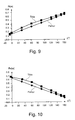
- So cadaver tests and results, as shown in Fig.3 and Fig.5 are adapted to be used as inputs for mathematical modelling of implant surfaces.
- the trace-lines Lt1 and Lt2 are very important as they are the basis for the definition of the guiding surfaces. Nevertheless they must not be part of the guiding surfaces and could be left out. They can be virtuel for the definition of the guiding surfaces and for the relative motion between femur and tibia.
- conical surfaces 17, 18 that control the rolling-gliding of the surfaces: Two cones with their centres at the centre Mb of the medial ball 1 roll and glide over the top of each other.
- the first cone for the tibia has the trace-line Lt1 as generator for the conical surface 18; the second cone for the femur has the trace-line Lt2 as generator for the conical surface 17.
- the cones can serve as auxiliary supporting surfaces at the lateral interior side of the trace-lines Lt1 and Lt2 in combination with the above described enforced gliding and rolling system.
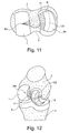
- Figure 11 is a view from approximately distal, which shows a conical surface 17 at the lateral femoral condyle.
- a band of this conical surface 17 could provide additional articular surface and support to its matching tibial counterpart 18, whereas the relation between gliding and rolling is controlled by the guiding curves Bi and Be.
- the conical surface 18 is shown on the tibia component 2 as if the lateral femur part would be transparent.
- FIG. 13 and 14 shows a large conical bearing surface 18 in extension and a small conical bearing surface 18 at a large flexion angle ⁇ . This arrangement allows for sufficient bearing surface at all flexion angles.
- the clearances between the tibial and femoral guiding features can be enlarged by machining the tibial parts with slightly larger guiding curves for the medial and lateral aspects. Having different tibial parts a surgon can choose which one would suit best a patient depending on the condition of the cruciates of the particular patient.
- the first guiding surface which drives from extension to flexion and the second guiding surface, which drives from flexion to extension may not be engaged simultaneously at the same flexion angle.
- Such guiding surfaces would form an envelope of laxities around a central path, whilst still allowing for steering effects of the contact surfaces.
- the range of laxities can be set correspondingly for different types of prostheses including ACL or PCL deficient knees.
- the trace-line Lt1 or the third segment can deflect allowing for the side curves to partially engage and can produce traction. If the material is not elastic enough, then there could be a pinching load between the articular surfaces, that can cause surface damage to the tibia component in a long run.
- Elastic materials could be as an example PU, elastomeric PU, PCU, PE or UHMW Polyethylene.
Landscapes
- Health & Medical Sciences (AREA)
- Orthopedic Medicine & Surgery (AREA)
- Physical Education & Sports Medicine (AREA)
- Cardiology (AREA)
- Oral & Maxillofacial Surgery (AREA)
- Transplantation (AREA)
- Engineering & Computer Science (AREA)
- Biomedical Technology (AREA)
- Heart & Thoracic Surgery (AREA)
- Vascular Medicine (AREA)
- Life Sciences & Earth Sciences (AREA)
- Animal Behavior & Ethology (AREA)
- General Health & Medical Sciences (AREA)
- Public Health (AREA)
- Veterinary Medicine (AREA)
- Prostheses (AREA)
Claims (13)
- Knieprothese für ein Kniegelenk mit einer Breite "w" mit einem kugelförmigen Femurkondylus (1) und einem entsprechenden Tibia-Hohlraum (11) auf der medialen Seite, wobei die Kugel (1) und der Hohlraum (11) eine Mitte "Mb", einen Radius "Rb" und eine Kugeloberfläche "Sb" aufweisen und ein kartesisches Koordinatensystem X, Y, Z definieren, befestigt an der Tibia, an ihrem Ursprung "O" in der Mitte "Mb", und mit einem seitlichen Kompartiment (8), dadurch gekennzeichnet,- dass auf dem seitlichen Kompartiment eine Verfolgungslinie "Lt1" von Kontaktpunkten "Pt1" für die Tibiakomponente (2) als eine vorbestimmte Kurve (15) auf einer Kugeloberfläche "Sc1" existiert, deren Mitte am Ursprung "O" liegt und die einen Radius in einem Bereich "Rc1" = 0,65 w +/- 0,25 w aufweist,- dass bei einem gegebenen Beugewinkel γ für jeden Kontaktpunkt "Pt1" auf einer Verfolgungslinie "Lt2" ein gemeinsamer Kontaktpunkt "Pt2" für eine Kugeloberfläche "Sc2", befestigt am Femur, existiert, die mit "Sc1" identisch ist und einen Ursprung "O" und einen Radius "Rc2" = Rc1 aufweist, wobei bei einem gegebenen Beugewinkel γ eine Ebene "E1" durch den Ursprung "O" und den gemeinsamen Kontaktpunkt Pt1/Pt2 existiert, die dieselben Führungskurven "Bi", "Be" auf dem Tibiateil und dem Femurteil enthält, "Bi" nach medial und "Be" nach lateral, wobei beide in einer geometrisch fixen Beziehung zu dem gemeinsamen Kontaktpunkt Pt1/Pt2 bleiben,- und dass zumindest eine der Führungskurven "Bi" und "Be" durch Veränderung des Beugewinkels γ progressiv ihre Form verändert, zur Erzeugung einer erzwungenen Gleit- und Rollbewegung in Beugerichtung oder in Streckrichtung.
- Knieprothese nach Anspruch 1, dadurch gekennzeichnet, dass die Führungskurven "Bi" und "Be" durch Veränderung des Beugewinkels γ progressiv ihre Form in entgegengesetzte Richtungen verändern, zur Erzeugung einer erzwungenen Gleit- und Rollbewegung in Beugerichtung und in Streckrichtung.
- Knieprothese nach Anspruch 1 oder 2, dadurch gekennzeichnet, dass die Führungskurven "Bi" und "Be" Bögen sind, die von gemeinsamen Kontaktpunkten Pt1/Pt2 beginnen.
- Knieprothese nach Anspruch 1 oder 3, dadurch gekennzeichnet, dass die Ebene E1 orthogonal zu einer Tangente "T1" der Verfolgungslinie Lt1 an dem gemeinsamen Kontaktpunkt Pt1/Pt2 ist, und dass die Führungskurven "Bi" und "Be" an dem gemeinsamen Kontaktpunkt Pt1/Pt2 eine Linie "T2" auf der Ebene E1 tangieren, die von dem gemeinsamen Kontaktpunkt zu der Oberfläche "Sb" der Kugel (1) gezeichnet ist.
- Knieprothese nach Anspruch 1 bis 4, dadurch gekennzeichnet, dass an jedem gemeinsamen Kontaktpunkt Pt1/Pt2 die Kurven "Bi" und "Be" Kreisbögen mit Radien Ri, Re sind.
- Knieprothese nach Anspruch 1 bis 5, dadurch gekennzeichnet, dass die vorbestimmte Kurve (15) durch Zusammentreffen der Kugeloberfläche "Sc1" mit einer Oberfläche eines Zylinders (5) erzeugt wird, die orthogonal zu einer Sagittalebene (4) steht und die durch eine kontinuierliche Kurve (Lc) auf der Sagittalebene (4) konstruiert wird.
- Knieprothese nach Anspruch 6, dadurch gekennzeichnet, dass die zur Konstruktion des Zylinders verwendete kontinuierliche Kurve auf einer Sagittalebene und zwischen zwei kreisförmigen Grenzen mit Radien R1 und R2 liegt, die eine gemeinsame Mitte "Ms" mit den Koordinaten x = 0,07 w; y = -0,794 w; z= 0,5 w und dem Radius R1 = 0,54 w + 0,08 w bzw. dem Radius R2 = 0,54 w - 0,08 w aufweisen.
- Knieprothese nach Anspruch 7, dadurch gekennzeichnet, dass der Radius R1 den Wert R1 = 0,54 w + 0,03 w und der Radius R2 den Wert R2 = 0,54 w - 0,03 w aufweist.
- Knieprothese nach Anspruch 1 bis 8, dadurch gekennzeichnet, dass bei jedem Beugewinkel γ eine Tangente T1 zu der Verfolgungslinie Lt1 an dem Kontaktpunkt Pt1 auch die Tangente für die Verfolgungslinie Lt2 auf der Kugeloberfläche "Sc2" des Femur ist, und dass bei jedem Beugewinkel der Ort der momentanen Drehachse (12) auf einer Ebene E1 liegt, die durch die Mitte Mb der medialen Kugel 1 verläuft und senkrecht zu der Tangente T1 der dreidimensionalen Verfolgungslinie Lt1 an Kontaktpunkten Pt1 für die Tibia ist.
- Knieprothese nach einem der Ansprüche 1 bis 9, konstruiert als Knietotalprothese mit einer Femurkomponente, die eine Einkerbung (9) ähnlich einer anatomischen Patella-Rinne aufweist, und mit einer Tibiakomponente (2) mit einer entsprechenden Form eines posterioren Ausschnitts (10) zur Beibehaltung eines der oder beider Kreuzbänder.
- Knieprothese nach einem der Ansprüche 1 bis 9, konstruiert als laterale unikompartimentelle Prothese, ausgelegt zur Aufrechterhaltung einer natürlichen Patella und Patella-Rinne in Kombination mit der kongruenten Artikulation zwischen dem natürlichen medialen Femurkondylus und der konvexen Geometrie der Tibia- und Meniskus-Geometrie.
- Knieprothese nach Anspruch 1 bis 11, dadurch gekennzeichnet, dass die Führungsflächen "Bi" und "Be" für die Tibia- und für die Femurkomponenten weniger kongruent für den mittleren Bereich des Beugewinkels γ sind als für die Endstellungen in voller Streckung und voller Beugung.
- Knieprothese nach Anspruch 1 bis 12, dadurch gekennzeichnet, dass konische Flächen 17, 18 auf der Innenseite der Verfolgungslinien Lt1 und Lt2 für zusätzliche Unterstützung hinzugefügt sind, deren Mitten an der Mitte Mb der medialen Kugel 1 liegen und die die Verfolgungslinie Lt1, Lt2 als Generator für die Kegel aufweisen.
Priority Applications (1)
| Application Number | Priority Date | Filing Date | Title |
|---|---|---|---|
| EP10749820.6A EP2464314B1 (de) | 2009-08-10 | 2010-08-10 | Knieprothese |
Applications Claiming Priority (3)
| Application Number | Priority Date | Filing Date | Title |
|---|---|---|---|
| EP09167563 | 2009-08-10 | ||
| PCT/EP2010/061572 WO2011018441A1 (en) | 2009-08-10 | 2010-08-10 | Knee prosthesis |
| EP10749820.6A EP2464314B1 (de) | 2009-08-10 | 2010-08-10 | Knieprothese |
Publications (2)
| Publication Number | Publication Date |
|---|---|
| EP2464314A1 EP2464314A1 (de) | 2012-06-20 |
| EP2464314B1 true EP2464314B1 (de) | 2015-12-23 |
Family
ID=41508033
Family Applications (1)
| Application Number | Title | Priority Date | Filing Date |
|---|---|---|---|
| EP10749820.6A Active EP2464314B1 (de) | 2009-08-10 | 2010-08-10 | Knieprothese |
Country Status (6)
| Country | Link |
|---|---|
| US (2) | US20120179265A1 (de) |
| EP (1) | EP2464314B1 (de) |
| JP (1) | JP5775870B2 (de) |
| CN (1) | CN102596108B (de) |
| CA (1) | CA2769376C (de) |
| WO (1) | WO2011018441A1 (de) |
Families Citing this family (21)
| Publication number | Priority date | Publication date | Assignee | Title |
|---|---|---|---|---|
| US8066776B2 (en) * | 2001-12-14 | 2011-11-29 | Btg International Limited | Tibial component |
| US9615929B2 (en) | 2009-01-23 | 2017-04-11 | Zimmer, Inc. | Posterior-stabilized total knee prosthesis |
| DE102009029360A1 (de) * | 2009-09-10 | 2011-03-24 | Aesculap Ag | Kniegelenkendoprothese |
| EP3470020B8 (de) | 2010-01-29 | 2025-10-29 | Smith & Nephew, Inc. | Knieprothese zum halten der kreuzbänder |
| US9132014B2 (en) | 2010-04-13 | 2015-09-15 | Zimmer, Inc. | Anterior cruciate ligament substituting knee implants |
| EP3332748B1 (de) * | 2010-07-24 | 2019-08-14 | Zimmer, Inc. | Asymmetrische tibiakomponenten für eine knieprothese |
| WO2013007747A1 (en) * | 2011-07-13 | 2013-01-17 | Zimmer Gmbh | Femoral knee prosthesis with diverging lateral condyle |
| JP5826025B2 (ja) * | 2011-12-28 | 2015-12-02 | 京セラメディカル株式会社 | 人工膝関節インプラント |
| DE102014106012B9 (de) | 2014-04-29 | 2015-09-17 | Aesculap Ag | Kniegelenkendoprothese |
| US12083019B2 (en) | 2015-07-22 | 2024-09-10 | William Andrew Hodge | Lateral and medial pivoting knee prosthesis |
| CN105030384B (zh) * | 2015-08-03 | 2018-04-10 | 北京威高亚华人工关节开发有限公司 | 一种全膝关节置换假体 |
| BR112018006652A2 (pt) * | 2015-10-07 | 2018-10-23 | Ceramtec Gmbh | endoprótese de joelho para substituição de pelo menos partes da articulação do joelho |
| DE102015119105A1 (de) | 2015-11-06 | 2017-05-11 | Aesculap Ag | Kniegelenkendoprothese |
| US9833324B2 (en) * | 2015-12-30 | 2017-12-05 | Eva15 Llc | Knee prosthetic implant |
| EP3400912B1 (de) | 2017-05-10 | 2019-11-20 | Howmedica Osteonics Corporation | Patientenspezifischer zusammengesetzter knieersatz |
| CN109172053B (zh) * | 2018-10-18 | 2024-07-09 | 陕西四正医疗器械有限责任公司 | 一种双间室膝关节假体 |
| EP3698761B1 (de) | 2019-02-22 | 2021-11-17 | Stryker European Operations Limited | Totale sprunggelenksprothese |
| US11129720B2 (en) | 2019-03-05 | 2021-09-28 | Jonathan P. GARINO | Cruciate replacing artificial knee |
| US12239541B2 (en) | 2019-04-11 | 2025-03-04 | Teijin Nakashima Medical Co., Ltd. | Artificial knee joint |
| US11419731B1 (en) | 2021-02-04 | 2022-08-23 | Jonathan P. GARINO | Modular artificial knee system |
| CN119837681B (zh) * | 2025-03-18 | 2025-08-29 | 北京纳通医疗科技控股有限公司 | 膝关节衬垫和膝关节假体 |
Family Cites Families (8)
| Publication number | Priority date | Publication date | Assignee | Title |
|---|---|---|---|---|
| GB9102633D0 (en) * | 1991-02-07 | 1991-03-27 | Finsbury Instr Ltd | Knee prosthesis |
| US5964808A (en) * | 1996-07-11 | 1999-10-12 | Wright Medical Technology, Inc. | Knee prosthesis |
| FR2796836B1 (fr) * | 1999-07-26 | 2002-03-22 | Michel Bercovy | Nouvelle prothese du genou |
| JP4409784B2 (ja) * | 2000-05-29 | 2010-02-03 | ツィマー ゲーエムベーハー | 人工膝関節 |
| US7160330B2 (en) * | 2003-01-21 | 2007-01-09 | Howmedica Osteonics Corp. | Emulating natural knee kinematics in a knee prosthesis |
| JP4045194B2 (ja) * | 2003-02-25 | 2008-02-13 | 京セラ株式会社 | 人工膝関節 |
| US7261740B2 (en) * | 2003-10-29 | 2007-08-28 | Wright Medical Technology, Inc. | Tibial knee prosthesis |
| GB0607544D0 (en) * | 2006-04-13 | 2006-05-24 | Pinskerova Vera | Knee prothesis |
-
2010
- 2010-08-10 EP EP10749820.6A patent/EP2464314B1/de active Active
- 2010-08-10 JP JP2012524214A patent/JP5775870B2/ja not_active Expired - Fee Related
- 2010-08-10 US US13/389,950 patent/US20120179265A1/en not_active Abandoned
- 2010-08-10 WO PCT/EP2010/061572 patent/WO2011018441A1/en not_active Ceased
- 2010-08-10 CA CA2769376A patent/CA2769376C/en active Active
- 2010-08-10 CN CN201080035357.3A patent/CN102596108B/zh not_active Expired - Fee Related
-
2015
- 2015-09-03 US US14/844,992 patent/US10292826B2/en active Active
Also Published As
| Publication number | Publication date |
|---|---|
| US20160151162A1 (en) | 2016-06-02 |
| JP5775870B2 (ja) | 2015-09-09 |
| JP2013501555A (ja) | 2013-01-17 |
| US20120179265A1 (en) | 2012-07-12 |
| WO2011018441A1 (en) | 2011-02-17 |
| EP2464314A1 (de) | 2012-06-20 |
| US10292826B2 (en) | 2019-05-21 |
| CN102596108A (zh) | 2012-07-18 |
| CN102596108B (zh) | 2014-10-01 |
| CA2769376C (en) | 2016-02-23 |
| CA2769376A1 (en) | 2011-02-17 |
Similar Documents
| Publication | Publication Date | Title |
|---|---|---|
| EP2464314B1 (de) | Knieprothese | |
| US11160659B2 (en) | Prosthesis system including tibial bearing component | |
| EP2254520B1 (de) | Kniegelenkstotalprothese mit nurbs-oberflächen hoher ordnung | |
| AU2009202848B2 (en) | Antero-posterior placement of axis of rotation for a rotating platform | |
| US9788955B2 (en) | Total knee replacement prosthesis with high order NURBS surfaces | |
| EP2165681B1 (de) | sowohl kongruent als auch inkongruent gelenkig gelagerte Endoprothese mit stationärem Lager | |
| US4822365A (en) | Method of design of human joint prosthesis | |
| EP0522822B1 (de) | Oberfläche einer Kniegelenkprothese | |
| EP0993812A2 (de) | Femorales Komponent für eine Knieprothese | |
| ZA200904950B (en) | Knee prosthesis with enhanced kinematics | |
| US20190209331A1 (en) | Systems and methods of implants to restore patient specific functon | |
| JP2013501555A5 (de) | ||
| Lian et al. | Patient-specific design and biomechanical evaluation of a novel bipolar femoral hemi-knee prosthesis | |
| van den Heever et al. | Development and testing of patient-specific knee replacements | |
| ZA200904949B (en) | Antero-posterior placement of axis of rotation for a rotating platform |
Legal Events
| Date | Code | Title | Description |
|---|---|---|---|
| PUAI | Public reference made under article 153(3) epc to a published international application that has entered the european phase |
Free format text: ORIGINAL CODE: 0009012 |
|
| 17P | Request for examination filed |
Effective date: 20120213 |
|
| AK | Designated contracting states |
Kind code of ref document: A1 Designated state(s): AL AT BE BG CH CY CZ DE DK EE ES FI FR GB GR HR HU IE IS IT LI LT LU LV MC MK MT NL NO PL PT RO SE SI SK SM TR |
|
| DAX | Request for extension of the european patent (deleted) | ||
| RAP1 | Party data changed (applicant data changed or rights of an application transferred) |
Owner name: ORTHOPAEDIC INNOVATION CENTRE INC. |
|
| RIN1 | Information on inventor provided before grant (corrected) |
Inventor name: AMIRI SHARAM Inventor name: WYSS URS Inventor name: COOKE THEODORE DEREK VERNON |
|
| GRAP | Despatch of communication of intention to grant a patent |
Free format text: ORIGINAL CODE: EPIDOSNIGR1 |
|
| INTG | Intention to grant announced |
Effective date: 20150109 |
|
| GRAJ | Information related to disapproval of communication of intention to grant by the applicant or resumption of examination proceedings by the epo deleted |
Free format text: ORIGINAL CODE: EPIDOSDIGR1 |
|
| GRAP | Despatch of communication of intention to grant a patent |
Free format text: ORIGINAL CODE: EPIDOSNIGR1 |
|
| INTG | Intention to grant announced |
Effective date: 20150701 |
|
| GRAS | Grant fee paid |
Free format text: ORIGINAL CODE: EPIDOSNIGR3 |
|
| GRAA | (expected) grant |
Free format text: ORIGINAL CODE: 0009210 |
|
| AK | Designated contracting states |
Kind code of ref document: B1 Designated state(s): AL AT BE BG CH CY CZ DE DK EE ES FI FR GB GR HR HU IE IS IT LI LT LU LV MC MK MT NL NO PL PT RO SE SI SK SM TR |
|
| REG | Reference to a national code |
Ref country code: GB Ref legal event code: FG4D |
|
| REG | Reference to a national code |
Ref country code: CH Ref legal event code: EP |
|
| REG | Reference to a national code |
Ref country code: IE Ref legal event code: FG4D |
|
| REG | Reference to a national code |
Ref country code: AT Ref legal event code: REF Ref document number: 766195 Country of ref document: AT Kind code of ref document: T Effective date: 20160115 |
|
| REG | Reference to a national code |
Ref country code: DE Ref legal event code: R096 Ref document number: 602010029720 Country of ref document: DE |
|
| REG | Reference to a national code |
Ref country code: SE Ref legal event code: TRGR |
|
| REG | Reference to a national code |
Ref country code: CH Ref legal event code: NV Representative=s name: DR. GRAF AND PARTNER AG INTELLECTUAL PROPERTY, CH |
|
| REG | Reference to a national code |
Ref country code: LT Ref legal event code: MG4D |
|
| REG | Reference to a national code |
Ref country code: NL Ref legal event code: MP Effective date: 20151223 |
|
| PG25 | Lapsed in a contracting state [announced via postgrant information from national office to epo] |
Ref country code: NO Free format text: LAPSE BECAUSE OF FAILURE TO SUBMIT A TRANSLATION OF THE DESCRIPTION OR TO PAY THE FEE WITHIN THE PRESCRIBED TIME-LIMIT Effective date: 20160323 Ref country code: LT Free format text: LAPSE BECAUSE OF FAILURE TO SUBMIT A TRANSLATION OF THE DESCRIPTION OR TO PAY THE FEE WITHIN THE PRESCRIBED TIME-LIMIT Effective date: 20151223 Ref country code: HR Free format text: LAPSE BECAUSE OF FAILURE TO SUBMIT A TRANSLATION OF THE DESCRIPTION OR TO PAY THE FEE WITHIN THE PRESCRIBED TIME-LIMIT Effective date: 20151223 |
|
| REG | Reference to a national code |
Ref country code: AT Ref legal event code: MK05 Ref document number: 766195 Country of ref document: AT Kind code of ref document: T Effective date: 20151223 |
|
| PG25 | Lapsed in a contracting state [announced via postgrant information from national office to epo] |
Ref country code: FI Free format text: LAPSE BECAUSE OF FAILURE TO SUBMIT A TRANSLATION OF THE DESCRIPTION OR TO PAY THE FEE WITHIN THE PRESCRIBED TIME-LIMIT Effective date: 20151223 Ref country code: NL Free format text: LAPSE BECAUSE OF FAILURE TO SUBMIT A TRANSLATION OF THE DESCRIPTION OR TO PAY THE FEE WITHIN THE PRESCRIBED TIME-LIMIT Effective date: 20151223 Ref country code: LV Free format text: LAPSE BECAUSE OF FAILURE TO SUBMIT A TRANSLATION OF THE DESCRIPTION OR TO PAY THE FEE WITHIN THE PRESCRIBED TIME-LIMIT Effective date: 20151223 Ref country code: GR Free format text: LAPSE BECAUSE OF FAILURE TO SUBMIT A TRANSLATION OF THE DESCRIPTION OR TO PAY THE FEE WITHIN THE PRESCRIBED TIME-LIMIT Effective date: 20160324 |
|
| PG25 | Lapsed in a contracting state [announced via postgrant information from national office to epo] |
Ref country code: ES Free format text: LAPSE BECAUSE OF FAILURE TO SUBMIT A TRANSLATION OF THE DESCRIPTION OR TO PAY THE FEE WITHIN THE PRESCRIBED TIME-LIMIT Effective date: 20151223 Ref country code: CZ Free format text: LAPSE BECAUSE OF FAILURE TO SUBMIT A TRANSLATION OF THE DESCRIPTION OR TO PAY THE FEE WITHIN THE PRESCRIBED TIME-LIMIT Effective date: 20151223 |
|
| REG | Reference to a national code |
Ref country code: FR Ref legal event code: PLFP Year of fee payment: 7 |
|
| PG25 | Lapsed in a contracting state [announced via postgrant information from national office to epo] |
Ref country code: SM Free format text: LAPSE BECAUSE OF FAILURE TO SUBMIT A TRANSLATION OF THE DESCRIPTION OR TO PAY THE FEE WITHIN THE PRESCRIBED TIME-LIMIT Effective date: 20151223 Ref country code: AT Free format text: LAPSE BECAUSE OF FAILURE TO SUBMIT A TRANSLATION OF THE DESCRIPTION OR TO PAY THE FEE WITHIN THE PRESCRIBED TIME-LIMIT Effective date: 20151223 Ref country code: EE Free format text: LAPSE BECAUSE OF FAILURE TO SUBMIT A TRANSLATION OF THE DESCRIPTION OR TO PAY THE FEE WITHIN THE PRESCRIBED TIME-LIMIT Effective date: 20151223 Ref country code: RO Free format text: LAPSE BECAUSE OF FAILURE TO SUBMIT A TRANSLATION OF THE DESCRIPTION OR TO PAY THE FEE WITHIN THE PRESCRIBED TIME-LIMIT Effective date: 20151223 Ref country code: PT Free format text: LAPSE BECAUSE OF FAILURE TO SUBMIT A TRANSLATION OF THE DESCRIPTION OR TO PAY THE FEE WITHIN THE PRESCRIBED TIME-LIMIT Effective date: 20160426 Ref country code: PL Free format text: LAPSE BECAUSE OF FAILURE TO SUBMIT A TRANSLATION OF THE DESCRIPTION OR TO PAY THE FEE WITHIN THE PRESCRIBED TIME-LIMIT Effective date: 20151223 Ref country code: SK Free format text: LAPSE BECAUSE OF FAILURE TO SUBMIT A TRANSLATION OF THE DESCRIPTION OR TO PAY THE FEE WITHIN THE PRESCRIBED TIME-LIMIT Effective date: 20151223 Ref country code: IS Free format text: LAPSE BECAUSE OF FAILURE TO SUBMIT A TRANSLATION OF THE DESCRIPTION OR TO PAY THE FEE WITHIN THE PRESCRIBED TIME-LIMIT Effective date: 20160423 |
|
| REG | Reference to a national code |
Ref country code: DE Ref legal event code: R097 Ref document number: 602010029720 Country of ref document: DE |
|
| PLBE | No opposition filed within time limit |
Free format text: ORIGINAL CODE: 0009261 |
|
| STAA | Information on the status of an ep patent application or granted ep patent |
Free format text: STATUS: NO OPPOSITION FILED WITHIN TIME LIMIT |
|
| PG25 | Lapsed in a contracting state [announced via postgrant information from national office to epo] |
Ref country code: DK Free format text: LAPSE BECAUSE OF FAILURE TO SUBMIT A TRANSLATION OF THE DESCRIPTION OR TO PAY THE FEE WITHIN THE PRESCRIBED TIME-LIMIT Effective date: 20151223 |
|
| 26N | No opposition filed |
Effective date: 20160926 |
|
| PG25 | Lapsed in a contracting state [announced via postgrant information from national office to epo] |
Ref country code: BE Free format text: LAPSE BECAUSE OF FAILURE TO SUBMIT A TRANSLATION OF THE DESCRIPTION OR TO PAY THE FEE WITHIN THE PRESCRIBED TIME-LIMIT Effective date: 20151223 |
|
| PG25 | Lapsed in a contracting state [announced via postgrant information from national office to epo] |
Ref country code: SI Free format text: LAPSE BECAUSE OF FAILURE TO SUBMIT A TRANSLATION OF THE DESCRIPTION OR TO PAY THE FEE WITHIN THE PRESCRIBED TIME-LIMIT Effective date: 20151223 |
|
| PG25 | Lapsed in a contracting state [announced via postgrant information from national office to epo] |
Ref country code: MC Free format text: LAPSE BECAUSE OF FAILURE TO SUBMIT A TRANSLATION OF THE DESCRIPTION OR TO PAY THE FEE WITHIN THE PRESCRIBED TIME-LIMIT Effective date: 20151223 |
|
| REG | Reference to a national code |
Ref country code: IE Ref legal event code: MM4A |
|
| PG25 | Lapsed in a contracting state [announced via postgrant information from national office to epo] |
Ref country code: IE Free format text: LAPSE BECAUSE OF NON-PAYMENT OF DUE FEES Effective date: 20160810 |
|
| REG | Reference to a national code |
Ref country code: FR Ref legal event code: PLFP Year of fee payment: 8 |
|
| PG25 | Lapsed in a contracting state [announced via postgrant information from national office to epo] |
Ref country code: LU Free format text: LAPSE BECAUSE OF NON-PAYMENT OF DUE FEES Effective date: 20160810 |
|
| PG25 | Lapsed in a contracting state [announced via postgrant information from national office to epo] |
Ref country code: HU Free format text: LAPSE BECAUSE OF FAILURE TO SUBMIT A TRANSLATION OF THE DESCRIPTION OR TO PAY THE FEE WITHIN THE PRESCRIBED TIME-LIMIT; INVALID AB INITIO Effective date: 20100810 Ref country code: CY Free format text: LAPSE BECAUSE OF FAILURE TO SUBMIT A TRANSLATION OF THE DESCRIPTION OR TO PAY THE FEE WITHIN THE PRESCRIBED TIME-LIMIT Effective date: 20151223 |
|
| PG25 | Lapsed in a contracting state [announced via postgrant information from national office to epo] |
Ref country code: TR Free format text: LAPSE BECAUSE OF FAILURE TO SUBMIT A TRANSLATION OF THE DESCRIPTION OR TO PAY THE FEE WITHIN THE PRESCRIBED TIME-LIMIT Effective date: 20151223 Ref country code: MK Free format text: LAPSE BECAUSE OF FAILURE TO SUBMIT A TRANSLATION OF THE DESCRIPTION OR TO PAY THE FEE WITHIN THE PRESCRIBED TIME-LIMIT Effective date: 20151223 Ref country code: MT Free format text: LAPSE BECAUSE OF NON-PAYMENT OF DUE FEES Effective date: 20160831 |
|
| REG | Reference to a national code |
Ref country code: FR Ref legal event code: PLFP Year of fee payment: 9 |
|
| PG25 | Lapsed in a contracting state [announced via postgrant information from national office to epo] |
Ref country code: BG Free format text: LAPSE BECAUSE OF FAILURE TO SUBMIT A TRANSLATION OF THE DESCRIPTION OR TO PAY THE FEE WITHIN THE PRESCRIBED TIME-LIMIT Effective date: 20151223 |
|
| PG25 | Lapsed in a contracting state [announced via postgrant information from national office to epo] |
Ref country code: AL Free format text: LAPSE BECAUSE OF FAILURE TO SUBMIT A TRANSLATION OF THE DESCRIPTION OR TO PAY THE FEE WITHIN THE PRESCRIBED TIME-LIMIT Effective date: 20151223 |
|
| PGFP | Annual fee paid to national office [announced via postgrant information from national office to epo] |
Ref country code: SE Payment date: 20220714 Year of fee payment: 13 Ref country code: IT Payment date: 20220712 Year of fee payment: 13 Ref country code: GB Payment date: 20220707 Year of fee payment: 13 Ref country code: DE Payment date: 20220712 Year of fee payment: 13 |
|
| PGFP | Annual fee paid to national office [announced via postgrant information from national office to epo] |
Ref country code: FR Payment date: 20220709 Year of fee payment: 13 |
|
| PGFP | Annual fee paid to national office [announced via postgrant information from national office to epo] |
Ref country code: CH Payment date: 20220803 Year of fee payment: 13 |
|
| REG | Reference to a national code |
Ref country code: DE Ref legal event code: R119 Ref document number: 602010029720 Country of ref document: DE |
|
| REG | Reference to a national code |
Ref country code: CH Ref legal event code: PL |
|
| GBPC | Gb: european patent ceased through non-payment of renewal fee |
Effective date: 20230810 |
|
| PG25 | Lapsed in a contracting state [announced via postgrant information from national office to epo] |
Ref country code: CH Free format text: LAPSE BECAUSE OF NON-PAYMENT OF DUE FEES Effective date: 20230831 |
|
| PG25 | Lapsed in a contracting state [announced via postgrant information from national office to epo] |
Ref country code: SE Free format text: LAPSE BECAUSE OF NON-PAYMENT OF DUE FEES Effective date: 20230811 |
|
| PG25 | Lapsed in a contracting state [announced via postgrant information from national office to epo] |
Ref country code: GB Free format text: LAPSE BECAUSE OF NON-PAYMENT OF DUE FEES Effective date: 20230810 |
|
| PG25 | Lapsed in a contracting state [announced via postgrant information from national office to epo] |
Ref country code: IT Free format text: LAPSE BECAUSE OF NON-PAYMENT OF DUE FEES Effective date: 20230810 Ref country code: GB Free format text: LAPSE BECAUSE OF NON-PAYMENT OF DUE FEES Effective date: 20230810 Ref country code: FR Free format text: LAPSE BECAUSE OF NON-PAYMENT OF DUE FEES Effective date: 20230831 Ref country code: DE Free format text: LAPSE BECAUSE OF NON-PAYMENT OF DUE FEES Effective date: 20240301 |