EP2464879B1 - Palier à roulement - Google Patents
Palier à roulement Download PDFInfo
- Publication number
- EP2464879B1 EP2464879B1 EP10735002.7A EP10735002A EP2464879B1 EP 2464879 B1 EP2464879 B1 EP 2464879B1 EP 10735002 A EP10735002 A EP 10735002A EP 2464879 B1 EP2464879 B1 EP 2464879B1
- Authority
- EP
- European Patent Office
- Prior art keywords
- row
- raceway
- bearing
- bearing ring
- balls
- Prior art date
- Legal status (The legal status is an assumption and is not a legal conclusion. Google has not performed a legal analysis and makes no representation as to the accuracy of the status listed.)
- Not-in-force
Links
- 238000005096 rolling process Methods 0.000 title claims description 131
- 230000005540 biological transmission Effects 0.000 claims description 18
- 239000011295 pitch Substances 0.000 description 36
- 239000004519 grease Substances 0.000 description 6
- 239000000314 lubricant Substances 0.000 description 6
- 230000001050 lubricating effect Effects 0.000 description 3
- 238000005461 lubrication Methods 0.000 description 3
- 230000009977 dual effect Effects 0.000 description 2
- 230000002093 peripheral effect Effects 0.000 description 2
- 230000006835 compression Effects 0.000 description 1
- 238000007906 compression Methods 0.000 description 1
- 238000010276 construction Methods 0.000 description 1
- 238000010438 heat treatment Methods 0.000 description 1
Images

Classifications
-
- F—MECHANICAL ENGINEERING; LIGHTING; HEATING; WEAPONS; BLASTING
- F16—ENGINEERING ELEMENTS AND UNITS; GENERAL MEASURES FOR PRODUCING AND MAINTAINING EFFECTIVE FUNCTIONING OF MACHINES OR INSTALLATIONS; THERMAL INSULATION IN GENERAL
- F16C—SHAFTS; FLEXIBLE SHAFTS; ELEMENTS OR CRANKSHAFT MECHANISMS; ROTARY BODIES OTHER THAN GEARING ELEMENTS; BEARINGS
- F16C19/00—Bearings with rolling contact, for exclusively rotary movement
- F16C19/54—Systems consisting of a plurality of bearings with rolling friction
- F16C19/55—Systems consisting of a plurality of bearings with rolling friction with intermediate floating or independently-driven rings rotating at reduced speed or with other differential ball or roller bearings
-
- F—MECHANICAL ENGINEERING; LIGHTING; HEATING; WEAPONS; BLASTING
- F16—ENGINEERING ELEMENTS AND UNITS; GENERAL MEASURES FOR PRODUCING AND MAINTAINING EFFECTIVE FUNCTIONING OF MACHINES OR INSTALLATIONS; THERMAL INSULATION IN GENERAL
- F16C—SHAFTS; FLEXIBLE SHAFTS; ELEMENTS OR CRANKSHAFT MECHANISMS; ROTARY BODIES OTHER THAN GEARING ELEMENTS; BEARINGS
- F16C33/00—Parts of bearings; Special methods for making bearings or parts thereof
- F16C33/30—Parts of ball or roller bearings
- F16C33/66—Special parts or details in view of lubrication
- F16C33/6603—Special parts or details in view of lubrication with grease as lubricant
-
- F—MECHANICAL ENGINEERING; LIGHTING; HEATING; WEAPONS; BLASTING
- F16—ENGINEERING ELEMENTS AND UNITS; GENERAL MEASURES FOR PRODUCING AND MAINTAINING EFFECTIVE FUNCTIONING OF MACHINES OR INSTALLATIONS; THERMAL INSULATION IN GENERAL
- F16C—SHAFTS; FLEXIBLE SHAFTS; ELEMENTS OR CRANKSHAFT MECHANISMS; ROTARY BODIES OTHER THAN GEARING ELEMENTS; BEARINGS
- F16C19/00—Bearings with rolling contact, for exclusively rotary movement
- F16C19/02—Bearings with rolling contact, for exclusively rotary movement with bearing balls essentially of the same size in one or more circular rows
- F16C19/14—Bearings with rolling contact, for exclusively rotary movement with bearing balls essentially of the same size in one or more circular rows for both radial and axial load
- F16C19/16—Bearings with rolling contact, for exclusively rotary movement with bearing balls essentially of the same size in one or more circular rows for both radial and axial load with a single row of balls
- F16C19/163—Bearings with rolling contact, for exclusively rotary movement with bearing balls essentially of the same size in one or more circular rows for both radial and axial load with a single row of balls with angular contact
-
- F—MECHANICAL ENGINEERING; LIGHTING; HEATING; WEAPONS; BLASTING
- F16—ENGINEERING ELEMENTS AND UNITS; GENERAL MEASURES FOR PRODUCING AND MAINTAINING EFFECTIVE FUNCTIONING OF MACHINES OR INSTALLATIONS; THERMAL INSULATION IN GENERAL
- F16C—SHAFTS; FLEXIBLE SHAFTS; ELEMENTS OR CRANKSHAFT MECHANISMS; ROTARY BODIES OTHER THAN GEARING ELEMENTS; BEARINGS
- F16C2240/00—Specified values or numerical ranges of parameters; Relations between them
- F16C2240/40—Linear dimensions, e.g. length, radius, thickness, gap
- F16C2240/70—Diameters; Radii
- F16C2240/76—Osculation, i.e. relation between radii of balls and raceway groove
-
- F—MECHANICAL ENGINEERING; LIGHTING; HEATING; WEAPONS; BLASTING
- F16—ENGINEERING ELEMENTS AND UNITS; GENERAL MEASURES FOR PRODUCING AND MAINTAINING EFFECTIVE FUNCTIONING OF MACHINES OR INSTALLATIONS; THERMAL INSULATION IN GENERAL
- F16C—SHAFTS; FLEXIBLE SHAFTS; ELEMENTS OR CRANKSHAFT MECHANISMS; ROTARY BODIES OTHER THAN GEARING ELEMENTS; BEARINGS
- F16C2240/00—Specified values or numerical ranges of parameters; Relations between them
- F16C2240/40—Linear dimensions, e.g. length, radius, thickness, gap
- F16C2240/70—Diameters; Radii
- F16C2240/80—Pitch circle diameters [PCD]
-
- F—MECHANICAL ENGINEERING; LIGHTING; HEATING; WEAPONS; BLASTING
- F16—ENGINEERING ELEMENTS AND UNITS; GENERAL MEASURES FOR PRODUCING AND MAINTAINING EFFECTIVE FUNCTIONING OF MACHINES OR INSTALLATIONS; THERMAL INSULATION IN GENERAL
- F16C—SHAFTS; FLEXIBLE SHAFTS; ELEMENTS OR CRANKSHAFT MECHANISMS; ROTARY BODIES OTHER THAN GEARING ELEMENTS; BEARINGS
- F16C2300/00—Application independent of particular apparatuses
- F16C2300/20—Application independent of particular apparatuses related to type of movement
- F16C2300/22—High-speed rotation
-
- F—MECHANICAL ENGINEERING; LIGHTING; HEATING; WEAPONS; BLASTING
- F16—ENGINEERING ELEMENTS AND UNITS; GENERAL MEASURES FOR PRODUCING AND MAINTAINING EFFECTIVE FUNCTIONING OF MACHINES OR INSTALLATIONS; THERMAL INSULATION IN GENERAL
- F16C—SHAFTS; FLEXIBLE SHAFTS; ELEMENTS OR CRANKSHAFT MECHANISMS; ROTARY BODIES OTHER THAN GEARING ELEMENTS; BEARINGS
- F16C2361/00—Apparatus or articles in engineering in general
- F16C2361/43—Clutches, e.g. disengaging bearing
-
- F—MECHANICAL ENGINEERING; LIGHTING; HEATING; WEAPONS; BLASTING
- F16—ENGINEERING ELEMENTS AND UNITS; GENERAL MEASURES FOR PRODUCING AND MAINTAINING EFFECTIVE FUNCTIONING OF MACHINES OR INSTALLATIONS; THERMAL INSULATION IN GENERAL
- F16C—SHAFTS; FLEXIBLE SHAFTS; ELEMENTS OR CRANKSHAFT MECHANISMS; ROTARY BODIES OTHER THAN GEARING ELEMENTS; BEARINGS
- F16C2361/00—Apparatus or articles in engineering in general
- F16C2361/61—Toothed gear systems, e.g. support of pinion shafts
Definitions
- US 3,737,202 shows three versions of the generic rolling bearing.
- the bearing balls within the respective row and between them between the rows are the same size, so have the same Wälzschreibradius.
- the first embodiment shows rolling bearings of the double-row angular contact ball bearing type.
- the second and third embodiments show hybrid forms of the types angular contact ball bearings and radial ball bearings.
- the first embodiment of the generic ball bearing provides two rows of balls with an inner bearing ring for the first row of balls, a common bearing ring for the first row and the second row and at least one outer bearing ring for the second row.
- the common bearing ring has an outer race for the balls of the radially inner first row and an inner race for the balls of the radially outer circumferential second row.
- the first row of balls has a pitch circle whose pitch circle diameter is smaller than the pitch circle diameter of the pitch circle of the second row. Since the balls all have the same diameter but different pitch circles, the diameters of the inner contact circles of the rows differ from each other and the outer contact circles of the rows to each other.
- Touch circles are the circles around the axis of rotation of the rolling bearing on which lie the contacts of the balls with the raceways.
- the second embodiment of the generic ball bearings according to US 3,737,202 has three rows of balls, a common bearing ring for the rows, and inner bearing rings and outer bearing rings. These three-row ball bearings can be divided into groups described below.
- the three-row ball bearings of the first group have a first row and two second rows of balls and are provided with a common bearing ring for the first and the second rows.
- the balls of the first row are arranged on a pitch circle, which is smaller than the pitch circle on which the balls of the two second rows are arranged.
- the pitch circles of the two second rows are equal to each other.
- the balls of the first row run on an outer leaf tracks of the common bearing ring and on an inner raceway of an inner ring.
- the common bearing ring also has two inner raceways for the two second rows.
- the ball bearing is also provided with two separate outer bearing rings, each of which is provided with an outer race for each of the two second rows.
- the three-row ball bearings of the second group after US 3,737,202 have two first rows of balls whose pitch circles are equal to each other, and a second row of balls and are provided with a common bearing ring for the rows.
- the pitch circle diameter of the pitch circles of the first rows are smaller than the diameter of the pitch circle of a second row.
- everyone the first rows is associated with an outer raceway on the common bearing ring.
- the inner raceways for the two first rows are each disposed on an inner race per row.
- the common bearing ring also has an inner race for the balls of the second row.
- the balls of the second row is also assigned to an outer race on an outer bearing ring.
- the third embodiment describes a ball bearing with two first rows and a second row.
- the balls of the three rows are arranged on axially adjacent pitch circles with the same diameter and have a common bearing ring.
- the common bearing ring has two outer raceways for the first rows and an inner raceway for the second row.
- each first row is an inner bearing ring and the second row associated with an outer bearing ring.
- DE 103 14 259 A1 shows an example of a double-row angular contact ball bearing of the type in which the two rows have a common bearing ring and different pitch circles.
- the total speed of the balls of the rows can be substantially halved by using a common bearing ring and thus the diameter-speed characteristic can also be substantially halved.
- the object of the invention is to provide a rolling bearing with reduced friction and improved life, which can be produced inexpensively.
- the raceway radius of either the inner race or the outer race of the first row is different than the raceway radius of the inner race on the common race.
- the common bearing ring is also called intermediate ring.
- the inner race lies radially outside on the intermediate ring.
- the inner race is that of the second row.
- the osculation of the rolling elements of the first row with the curvature of the inner and the outer race is different than the osculation of the rolling elements of the second row with the curvature of its inner race.
- the friction determines the heat generated in the bearing and thus influences the temperature of the bearing parts and the lubricant.
- the friction in the bearing depends on the speed. The higher the speed, the higher the friction becomes.
- the friction leads to resistances against the rotation of the bearing, which are also referred to as friction moments.
- friction moments In rolling bearings of the generic type of the prior art, therefore, different relative speeds and thus different friction torques are generated in rows with different pitch circles. Differences in the friction moments lead to uneven loads as well as temperature differences in the bearings. The fat life must therefore be measured according to the values of the series with the larger pitch circle diameter.
- the osculation on raceways of rows exposed to other deformations in operation than other raceways may be greater or less than those of races with other deformations.
- the portion of higher friction caused by different deformation can be compensated in a targeted manner by the choice of another osculation on the affected raceway.
- An embodiment of the invention provides that the raceway radius of the inner raceway of the first row on the inner bearing ring is smaller than the raceway radius of the inner raceway of the second row on the common bearing ring.
- the osculation of the rolling elements of the first row with the curvature of the outer race is less than the osculation of the rolling elements of the second row with the curvature of the inner raceway on the intermediate ring.
- raceway radius of the outer race for the rolling elements of the first row on the common bearing ring is smaller than the raceway radius of the inner raceway for the second rolling elements on the common bearing ring.
- the osculation between the rolling elements of the first row and the curvature of the outer raceway on the intermediate ring is less than the osculation between the curvature of the inner raceway on the intermediate ring and the rolling elements of the second row.
- a further embodiment of the invention provides that the raceway radius of the inner raceway on the common bearing ring is smaller than the raceway radius of the outer raceway of the second row.
- the osculation between the rolling elements of the second row and the curvature of the inner race on the common bearing ring smaller than the osculation between the rolling elements of the second row and the curvature of the outer raceway.
- a further embodiment of the invention provides that the raceway radius of the inner race of the first row is smaller than the raceway radius of the outer raceway for the first row on the common bearing ring. Further, in this connection, it is provided that the raceway radius of the outer race for the first row on the common bearing ring is smaller than the raceway radius of the inner race for the second row on the common race and that the raceway radius of the inner race for the second row on the common bearing ring is smaller than the raceway radius of the outer raceway for the second row.
- the lobes of the rolling elements of each row with their outer races are greater than the lobes of the rolling elements of the same row with the curvatures of the respective inner raceway.
- the Schmiegonne between the rolling elements of the first row and the curvatures of their tracks are smaller than the Schmiegonne between the rolling elements of the second row and the curvatures of their careers.
- the Schmiegungstech are particularly in double-row angular contact ball bearings with a common bearing ring as an intermediate ring
- the invention also relates to all variants and groups of bearings, which are described in the chapter "Background of the invention”.
- the first rows differ from the second rows by the diameter of their pitch circles and / or by the type of bearing assembly. It is irrelevant how many first rows and second rows has the rolling bearing. However, all first rows of a bearing have the same pitch circle and / or are of the same bearing type. Accordingly, all second rows of a rolling bearing have the same pitch circles among each other and / or are of the same bearing type. It is also conceivable that the rolling bearing according to the invention has third, fourth and nth rows of rolling elements, the differ from the series with the other ordinal numbers by other subcircles and / or bearing types. Thus, it is conceivable that radial ball bearings are combined with angular contact ball bearings and or four-point bearings in a bearing assembly. The invention applies to rolling bearings in which all bearing rolling elements of the rows have the same diameter to each other.
- a common bearing ring is a one-piece or composed of any number of pieces component to understand at which roll at least two different from the pitch circle or type rows rolling elements, which is arranged as an intermediate ring between these rows, and therefore at half the speed of the total speed of the bearing rotates.
- Inner raceways are the raceways of a row that are closer to the axis of rotation than the outer raceway in the same row.
- the contours of the inner raceways are described about the axis of rotation by outer circumferences and the contours of the outer raceways by mecanicumflinde.
- These definitions of the tracks also allow the inner race (s) of a series in whole or in part to be described by outer circumferences that are larger than the inner circumferences that describe the outer race of one or more other ranks.
- the raceways are formed on components that are either the classic rolling bearing rings or directly on shafts, bolts, housings and hollow cylindrical components of any kind.
- Angular contact bearings are to be understood as meaning the bearing arrangements in which the pressure lines between the contacts of the rolling elements on the inner raceway and the outer raceways do not extend radially as seen in the deep groove ball bearings to the bearing center axis but obliquely therewith.
- the pressure line extends in an imaginary axially along the axis of rotation of the bearing and extending at the contact of the rolling elements with the respective raceway through the rolling elements and raceways laid cutting plane, between the contacts of the rolling elements with the inner race and the outer race.
- the rolling elements of the first row touch the inner race on the contact at an encircling around the axis of rotation inner Bercken Vietnamese.
- the diameter of the Bercken Vietnamesees is smaller than it is the diameter of a rotating around the axis of rotation inner Bercken Vietnamesees at the contact of the rolling elements of the second row with the inner raceway on the bearing ring.
- the Berziernike are the imaginary and circulating around the axis of rotation of the rolling bearing circles on each of a raceway, which are defined by the contacts each one row with the track. It is distinguished between inner Berstoff Vietnameseen on the inner raceway and outer Berschreib Vietnameseen on the outer raceway.
- the contact circles are defined in the respective contact of the nominal diameter of the rollers or balls.
- the contact circles on the inner race are in the same radial plane as the contact circles on the outer raceways. In angular contact ball bearings, the contact circles lie in different axially adjacent radial planes.
- An embodiment of the invention provides that both rows of the rolling bearing are arranged in an angular contact ball bearing arrangement, so that the rolling bearing is a double-row angular contact ball bearing with a common intermediate ring. It is further provided that the pressure lines of both angular contact ball bearing rows with their common axis of rotation enclose the same pressure angle between them.
- the angular contact ball bearing is formed in two rows with a first row of balls and a second row of balls and the common bearing ring between the rows.
- the common bearing ring has the outer race for the balls of the first row and the inner race for the balls of the second row.
- the osculation between the balls of the first row and the curvature of one of the races of the first row are smaller than the pitches of the balls of the second row with the curvatures of at least one of the races for the second row.
- the angular contact ball bearing has an inner bearing ring for the first row, the common bearing ring between the first row and the second row and an outer bearing ring for the second row.
- the bearing rings are radially concentric with each other and axially at least partially nested in one another such that the common bearing ring surrounds at least one axial portion of the inner ring and the outer bearing ring circumferentially surrounds at least one axial portion of the common bearing ring.
- the osculation between the rolling elements of the first row and the curvature of the inner race on the inner ring is preferably less than the osculation between the rolling elements of the first row and the curvature of the outer race on the common bearing ring.
- the osculation between the rolling elements of the first row and the curvature of the outer race on the common bearing ring is less than the osculation between the rolling elements of the second row and the inner raceway on the common bearing ring.
- the osculation between the second-row rolling elements and the outer-race curvature on the outer ring is the largest in the angular contact ball bearing, so that the values of osculation on the contacts in the rolling bearing become larger from one track to the next as seen radially from inside to outside.
- the pitch circle is to be understood as the imaginary circle about the axis of rotation, which runs through the centers of rotation of the rolling bodies which are adjacent to one another in the direction of contact.
- the centers of rotation lie on the axes of rotation of rollers or are centers of balls.
- a ball roller bearing has as rolling elements so-called ball rollers, which are also called spherical discs.
- a ball roller is a roller whose rotationally symmetrical lateral surfaces are described by a spherical radius extending from the center of the ball roller.
- the ball rollers have deviating from the ball basic shape flattened edges.
- the circular surface-shaped flanks are arranged concentrically with respect to the axis of rotation of the spherical rollers and parallel to one another such that they are pierced perpendicularly by the axis of rotation.
- roller bearings whose rollers have a rotationally symmetrical and convex-spherical surface relative to their own axis of rotation.
- the contour of the surface is described in axial sections along the axis of rotation of the rollers by one or more radii whose puncture points lie at any distance from the axis of rotation of the roller or lie on the axis of rotation, but in the latter case are larger than the largest radial diameter of the roller.
- the invention relates to the genus remplireihiger bearings in which the number of bearing rings is greater, smaller or equal to the number of WälzMech-298.
- a well-known measure for reducing the peripheral speed is the reduction of the diameter of the pitch circle.
- the pitch circle can not be reduced, since the necessary load rating can no longer be achieved.
- Such measures are also set by the dimensions of the surrounding construction limits. This is especially true for nested arrangements in dual clutch transmissions and their clutches.
- the bearing assembly includes at least one biased double row angular contact ball bearing having at least a first row of balls, at least a second row of balls, and a common bearing ring between the rows.
- the common bearing ring has, according to the examples described above, an outer race for the balls of the first row and an inner race for the balls of the second row.
- the angular contact ball bearing may be a support bearing or at least a release bearing.
- the angular contact ball bearing is double row with a first row balls and a second row balls and a common Bearing ring between the rows.
- the common bearing ring has an outer race for the balls of the first row and an inner race for the balls of the second row.
- the lobes between the balls of the first row and at least the curvature of one of the races of the first row are smaller than the lugs of the balls of the second row with the curvatures of at least one of the races for the second row.
- the bearing rings are radially concentric with each other and axially at least partially nested so that the common bearing ring at least an axial portion of the inner ring and the outer bearing ring at least an axial portion of the common bearing ring circumferentially surrounds.
- the osculation between the rolling elements of the first row and the curvature of the inner race on the inner ring are less than the osculation between the rolling elements of the first row and the curvature of the outer with regard to previously listed ratios and relations and concrete numerical values Running track on the common bearing ring.
- the osculation between the rolling elements of the first row and the curvature of the outer raceway on the common bearing ring is less than the osculation between the rolling elements of the second row and the inner raceway on the common bearing ring.
- the osculation between the rolling elements of the second row and the curvature of the outer raceway on the outer ring is the largest in angular contact ball bearings.
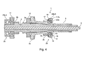
- FIG. 4 - FIG. 4 shows a transmission shaft assembly 1 for a non-illustrated transmission with two transmission shafts 2 and 3, by a prestressed Bearing assembly 20 is mounted.
- the bearing assembly 20 has a rolling bearing 20a in the form of an angular contact ball bearing 4 and a rolling bearing 20b in the form of a double row angular contact ball bearing 5.
- the angular contact ball bearing 5 is formed in two rows with at least a first row 6 balls 6a and at least a second row 7 balls 6a and a common bearing ring 8 between the rows.
- the transmission shaft 2 is partially inserted into the transmission shaft 3, has gears 2 a, 2 b, 11 and 12 and is rotatably mounted relative to this about the rotation axis 9.
- the transmission shaft 3 is provided with gears 3a and 3b.
- the rolling bearing 20a is in FIG. 4 single row and may alternatively be designed as a double-row angular contact ball bearing 5.
- the angular contact ball bearing 5 has an inner bearing ring 13, an outer bearing ring 14 and the common bearing ring 8: the latter is also referred to as an intermediate ring.
- the inner bearing ring 13 is provided with an inner race 15.
- the common bearing ring 8 has radially inwardly an outer race 16 for the row 6 and radially outside an inner race 17 for the row 7.
- an outer race 18 is turned radially inwardly.
- the bearing rings 8, 13 and 14 are arranged concentrically to the rotation axis 9 and partially nested.
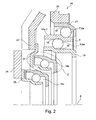
- FIG. 2 - FIG. 2 shows a section of a clutch assembly of a clutch not shown in detail of a dual clutch transmission, not shown.
- the rolling bearing assembly 10 shown therein has a rolling bearing 10a in the form of a double row angular contact ball bearing 5 with at least a first row 6 balls 6a and at least a second row 7 balls 6a and a common bearing ring 8 between the rows 6 and 7, wherein the common bearing ring 8 between the rows is arranged.
- the rolling bearing assembly 10 provides further rolling bearings 10b and 10c in the form of angular contact ball bearings, which are designed as single-row clutch release bearing but can also be carried out in two rows within the meaning of the invention.
- the rolling bearings 10b and 10c are provided with pressure flanges 22 and 26, respectively.
- Each of the pressure flanges 22 is located at spring ends 23 and 24 of a respective compression spring of the clutch, of which only one example is shown in each case.
- the roller bearing 10 a is a support bearing, which sits in a rotating about the rotation axis 9 clutch cover 25.
- the rolling bearing 10a has an inner bearing ring 19 and an outer bearing ring 21 and the common bearing ring 8 designed as an intermediate ring.
- the inner bearing ring 19 On the inner bearing ring 19, the inner race 15 and on the common ring, the outer race 16 for the first row 6 is formed.
- the common bearing ring 8 is formed radially outwardly with an inner race 17 for the second row 7, which is radially opposite to the outer race 18 on the outer bearing ring 21.
- the bearing rings 8, 19 and 21 are partially nested and arranged concentrically to the axis of rotation 9.
- FIG. 3 It is also conceivable that at least the rolling bearing 10b, as in FIG. 3 alternatively based on the detail Z after FIG. 2 is formed, two rows with the row 6 of balls 6a, the common bearing ring 8 and the row 7 of balls 6a is formed.
- the rolling bearing 10b has in this case an inner bearing ring 19 and an outer bearing ring 21 and the common bearing ring 8 designed as an intermediate ring.
- the common bearing ring 8 is formed radially outwardly with an inner race 17 for the second row 7, which is radially opposite to the outer race 18 on the outer race 21.
- FIG. 1 - The rolling bearings 10a, 10b and 20b have a first row 6 and a second row 7, each with rolling elements 27 in the form of balls 6a and a common bearing ring 8 for both rows 6 and 7.
- FIG. 1 shows a detail of the respective rolling bearing 10a, 10b and 20b in an imaginary axial plane along the axis of rotation 9 extending cutting plane, which was selected purely randomly from a number of other possible cutting planes.
- the possible cutting planes correspond to the number of Wälzköper 27 per row 6 or 7.
- the cutting planes are placed on the contacts 28, 29, 30 and 31 through the raceways 15, 16, 17 and 18 through the respective center 32 of the rolling elements 27.
- the contacts 28, 29, 30 and 31 are, since the rolling elements 27 are balls 6a, almost punctiform in the unloaded state.
- the centers 32 of the balls 6a of the first row 6 lie on a common pitch circle with the pitch circle diameter d ml and the Center points 32 of the balls 6a of the second row 7 on the pitch circle with the pitch circle diameter d m2 .
- the rolling elements 27 run on the respective raceways 15, 16, 17 and 18 at different speeds, so that the position of the centers 32 and thus the contacts 28 and 29 of the balls 6a of the row 6 to The centers 32 and the contacts 30 and 31 of the row 7 are more random with each other and they rarely lie on a common line. Therefore, by any selected cutting plane defined by the center 32 of at least one of the balls 6a of any of the rows 6 or 7, other balls 6b need not necessarily be cut at the center 32.
- the pressure lines 33 are all inclined at the same helix angle ⁇ to the rotation axis 9.
- the bearing ring 8 is provided with a radially outer race 16 for the trained as balls 6a rolling elements 27 of the first row 6.
- the bearing ring has an inner race 17 for the balls 6 a of the second row 7.
- the balls of the two rows 6 and 7 have the same diameter, so that the radii of the balls R K1 and R K2 are also the same.
- the Rolling elements 27 of each of the rows 6 are in touching contact with the inner race 15 and the outer race 16.
- the rolling elements of the row 7 are each in touching contact with the inner race 17 and an outer raceway 18.
- the contour of the inner race 15 is predetermined in the respective cutting plane at the contact 28 by the raceway radius R 1Li .
- the outer race 16 on the common bearing ring 8 has the raceway radius R 1La .
- the inner raceway 17 of the second row 7 has in contact 30 the radius R 2Li and the raceway 18 in contact 31 with the balls 6 the raceway radius R 2La .
- the contours of the balls are described by the radius R K1 , the contours of the rolling elements 27 and the contours of the raceways 15, 16, 17 and 18 in the respective sectional planes from the center of rotation 32 are convexly convex in the same directions.
- the sphere radius R K1 R K2 ⁇ R 1Li ⁇ R 1La ⁇ R 2Li ⁇ R 2La and at least one raceway radius R 1Li or R 1La ⁇ R 2Li .
- R 1Li ⁇ R 2Li Furthermore, R 1La ⁇ R 2Li .
Landscapes
- Engineering & Computer Science (AREA)
- General Engineering & Computer Science (AREA)
- Mechanical Engineering (AREA)
- Rolling Contact Bearings (AREA)
Claims (14)
- Palier à roulement (10a, 10b, 20b) qui comprend au moins une première rangée (6) de corps de roulement (27) et une deuxième rangée (7) de corps de roulement (27) et une bague de palier commune (8) pour les deux rangées (6, 7),- la bague de palier (8) comprenant un chemin de roulement extérieur (16) pour les corps de roulement (27) de la première rangée (6) et un chemin de roulement intérieur (17) pour les corps de roulement (27) de la deuxième rangée (7),- les corps de roulement (27) dans chacune des rangées (6, 7) étant à chaque fois en contact contigu avec un chemin de roulement intérieur (15, 17) et un chemin de roulement extérieur (16, 18),- les contours des chemins de roulement (15, 16, 17, 18) dans des plans de coupe imaginaires s'étendant axialement le long de l'axe de rotation (9) étant prédéfinis à chaque fois par au moins un rayon de chemin de roulement orienté dans le plan de coupe respectif, les plans de coupe étant définis au niveau du contact par le chemin de roulement et par le corps de roulement (27) respectif,- les contours des corps de roulement (27) étant décrits au moins dans les plans de coupe par au moins un rayon de corps de roulement d'une manière à chaque fois bombée par rapport à un centre de rotation (32) des corps de roulement (27),- les contours des corps de roulement (27) et des chemins de roulement (15, 16, 17, 18) dans les plans de coupe respectifs étant courbés de manière convexe dans les mêmes directions tel que considéré à partir du centre de rotation (32),
et les corps de roulement (27) de la première rangée (6) présentant le même rayon de corps de roulement que les corps de roulement (27) de la deuxième rangée (7), caractérisé en ce que le rayon de chemin de roulement de l'un des chemins de roulement (15, 16) pour la première rangée (6) est différent du rayon de chemin de roulement du chemin de roulement intérieur (17) sur la bague de palier (8). - Palier à roulement selon la revendication 1, caractérisé en ce que le rayon de chemin de roulement du chemin de roulement intérieur (15) de la première rangée (6) est inférieur au rayon de chemin de roulement du chemin de roulement intérieur (17) sur la bague de palier.
- Palier à roulement selon la revendication 1, caractérisé en ce que le rayon de chemin de roulement du chemin de roulement extérieur (16) de la première rangée (6) sur la bague de palier (8) est inférieur au rayon de chemin de roulement du chemin de roulement intérieur (17) sur la bague de palier (8).
- Palier à roulement selon la revendication 1, caractérisé en ce que le rayon de chemin de roulement du chemin de roulement intérieur (17) sur la bague de palier (8) est inférieur au rayon de chemin de roulement du chemin de roulement extérieur (18) de la deuxième rangée (7).
- Palier à roulement selon la revendication 1, caractérisé en ce que le rayon de chemin de roulement du chemin de roulement intérieur (15) de la première rangée (6) est inférieur au rayon de chemin de roulement du chemin de roulement extérieur (16) de la première rangée (6) sur la bague de palier (8).
- Palier à roulement selon la revendication 5, caractérisé en ce que le rayon de chemin de roulement du chemin de roulement extérieur (16) de la première rangée (6) sur la bague de palier (8) est inférieur au rayon de chemin de roulement du chemin de roulement intérieur (17) de la deuxième rangée (7) sur la bague de palier (8), et en ce que le rayon de chemin de roulement du chemin de roulement intérieur (17) sur la bague de palier (8) est inférieur au rayon de chemin de roulement du chemin de roulement extérieur (18) de la deuxième rangée (7).
- Palier à roulement selon la revendication 1, caractérisé en ce que le centre du rayon de corps de roulement est le centre de rotation (32).
- Ensemble de paliers à roulement selon la revendication 7, caractérisé en ce que les corps de roulement (27) sont des billes (6a).
- Palier à roulement selon la revendication 8, caractérisé en ce que les rangées (6, 7) sont à chaque fois disposées suivant un agencement de palier à billes à contact oblique.
- Palier à roulement selon la revendication 9, caractérisé en ce que les lignes de pression (33), inclinées de l'angle d'inclinaison α par rapport à l'axe de rotation, des deux rangées (6, 7) sont inclinées suivant des angles d'inclinaison α de même amplitude par rapport à l'axe de rotation (9).
- Ensemble d'arbre de transmission (1) pour une transmission comprenant au moins un arbre de transmission qui est monté au moyen d'un ensemble de paliers à roulement précontraint, caractérisé en ce qu'au moins un palier à roulement (20) de l'ensemble de paliers à roulement (20) est formé par au moins un palier à billes à contact oblique (5) à deux rangées comprenant au moins une première rangée (6) de billes (6a) et au moins une deuxième rangée (7) de billes (6a) et une bague de palier commune (8) entre les rangées (6, 7), la bague de palier commune (8) comprenant un chemin de roulement extérieur (16) pour les billes (6a) de la première rangée (6) et un chemin de roulement intérieur (17) pour les billes (6a) de la deuxième rangée (7), et les osculations entre les billes (6a) de la première rangée (6) et au moins la courbure de l'un des chemins de roulement (15, 16) de la première rangée (6) étant inférieures aux osculations des billes (6a) de la deuxième rangée (7) avec les courbures d'au moins l'un des chemins de roulement (17, 18) pour la deuxième rangée (7).
- Ensemble de paliers à roulement dans au moins un embrayage d'une transmission à embrayage double qui comprend au moins un palier à billes à contact oblique, caractérisé en ce que le palier à billes à contact oblique (5) est formé en deux rangées avec au moins une première rangée (6) de billes (6a) et au moins une deuxième rangée (7) de billes (6a) et une bague de palier commune (8) entre les rangées (6, 7), la bague de palier commune (8) comprenant un chemin de roulement extérieur (16) pour les billes (6a) de la première rangée (6) et un chemin de roulement intérieur (17) pour les billes (6a) de la deuxième rangée (7), et les osculations entre les billes (6a) de la première rangée (6) et au moins la courbure de l'un des chemins de roulement (15, 16) de la première rangée (6) étant inférieures aux osculations des billes (6a) de la deuxième rangée (7) avec les courbures d'au moins l'un des chemins de roulement (17, 18) pour la deuxième rangée (7).
- Ensemble de paliers à roulement selon la revendication 12, caractérisé en ce que le palier à billes à contact oblique (5) comprend une bague de palier intérieure (19) pour la première rangée (6), la bague de palier commune (8) entre une première rangée (6) et une deuxième rangée (7) et une bague de palier extérieure (21) pour la deuxième rangée (7), les bagues de palier (8, 19, 21) étant imbriquées de manière radialement concentrique les unes par rapport aux autres et axialement au moins partiellement les unes dans les autres de telle sorte que la bague de palier commune (8) vienne en prise autour d'au moins une portion axiale de la bague de palier intérieure (19) et que la bague de palier extérieure (21) vienne en prise autour d'au moins une portion axiale de la bague de palier commune (8) du côté périphérique.
- Ensemble de paliers à roulement selon la revendication 13, caractérisé en ce que l'osculation entre les corps de roulement (27) de la première rangée (6) et la courbure du chemin de roulement intérieur (15) sur la bague de palier intérieure (19) est inférieure à l'osculation entre les corps de roulement (27) de la première rangée (6) et la courbure du chemin de roulement extérieur (16) sur la bague de palier commune, et en ce que l'osculation entre les corps de roulement (27) de la première rangée (6) et la courbure du chemin de roulement extérieur (16) sur la bague de palier commune (8) est inférieure à l'osculation entre les corps de roulement (27) de la deuxième rangée (7) et le chemin de roulement intérieur (17) sur la bague de palier commune (8), l'osculation entre les corps de roulement (27) de la deuxième rangée (7) et la courbure du chemin de roulement extérieur (18) sur la bague extérieure (21) étant la plus grande dans le palier à billes à contact oblique (5).
Applications Claiming Priority (2)
| Application Number | Priority Date | Filing Date | Title |
|---|---|---|---|
| DE102009037571A DE102009037571A1 (de) | 2009-08-14 | 2009-08-14 | Wälzlager |
| PCT/EP2010/060525 WO2011018314A1 (fr) | 2009-08-14 | 2010-07-21 | Palier à roulement |
Publications (2)
| Publication Number | Publication Date |
|---|---|
| EP2464879A1 EP2464879A1 (fr) | 2012-06-20 |
| EP2464879B1 true EP2464879B1 (fr) | 2014-09-10 |
Family
ID=42935533
Family Applications (1)
| Application Number | Title | Priority Date | Filing Date |
|---|---|---|---|
| EP10735002.7A Not-in-force EP2464879B1 (fr) | 2009-08-14 | 2010-07-21 | Palier à roulement |
Country Status (5)
| Country | Link |
|---|---|
| US (1) | US8646982B2 (fr) |
| EP (1) | EP2464879B1 (fr) |
| CN (1) | CN102472317B (fr) |
| DE (1) | DE102009037571A1 (fr) |
| WO (1) | WO2011018314A1 (fr) |
Families Citing this family (16)
| Publication number | Priority date | Publication date | Assignee | Title |
|---|---|---|---|---|
| CN102221047A (zh) * | 2011-06-02 | 2011-10-19 | 赵忠 | 多套圈轴承用中间层套圈 |
| CN102322478B (zh) * | 2011-06-02 | 2015-09-30 | 赵忠 | 带变径中间层套圈的多套圈轴承 |
| JP2013054810A (ja) * | 2011-09-06 | 2013-03-21 | Seiko Instruments Inc | 軸受装置、及び情報記録再生装置 |
| US9245673B2 (en) | 2013-01-24 | 2016-01-26 | Basf Se | Performance improvement of magnetocaloric cascades through optimized material arrangement |
| US9593756B2 (en) | 2013-07-31 | 2017-03-14 | American Axle & Manufacturing, Inc. | Bearing assembly configured to handle axial and radial loads |
| US9188107B2 (en) * | 2013-08-30 | 2015-11-17 | General Electric Company | Wind turbine bearings |
| US9822814B2 (en) | 2013-10-17 | 2017-11-21 | Aktiebolaget Skf | Bearing for combined loads |
| DE102013221685A1 (de) * | 2013-10-25 | 2015-04-30 | Schaeffler Technologies Gmbh & Co. Kg | Wälzlager |
| CN104819208A (zh) * | 2014-01-31 | 2015-08-05 | 郝继先 | 串列式自调超高速轴承 |
| DE102014003471A1 (de) * | 2014-03-05 | 2015-09-10 | Heidelberger Druckmaschinen Ag | Wälzlager mit doppeltem Freilauf |
| US9382940B2 (en) | 2014-05-12 | 2016-07-05 | Schaeffler Technologies AG & Co. KG | Triple race angular contact bearing |
| DE102015207105A1 (de) | 2015-04-20 | 2016-10-20 | Schaeffler Technologies AG & Co. KG | Schrägkugellager |
| US20160327093A1 (en) * | 2015-05-06 | 2016-11-10 | Michael D. Johns | Bearing for use in directional drilling |
| US9689424B1 (en) * | 2016-05-17 | 2017-06-27 | Schaeffler Technologies AG & Co. KG | Tiered axial taper roller bearing with common center ring |
| CN106355039B (zh) * | 2016-10-21 | 2019-04-26 | 河南科技大学 | 基于独立接触副的滚动轴承疲劳寿命与可靠度计算方法 |
| US11453487B2 (en) * | 2018-06-28 | 2022-09-27 | Sikorsky Aircraft Corporation | Redundant helicopter pitch change bearing |
Family Cites Families (14)
| Publication number | Priority date | Publication date | Assignee | Title |
|---|---|---|---|---|
| GB835421A (en) | 1955-08-05 | 1960-05-18 | Vyzk Ustav Pro Valiva Loziska | High speed bearing |
| US3011364A (en) * | 1959-02-04 | 1961-12-05 | Barden Corp | Ball bearing speed reducer |
| US3597029A (en) * | 1969-08-18 | 1971-08-03 | Elias M Marcum | Planetary bearing assembly |
| US3737202A (en) | 1971-07-19 | 1973-06-05 | Ackley D | Redundant bearing |
| US4045100A (en) * | 1973-02-14 | 1977-08-30 | Societe Nouvelle De Roulements | Concentric antifriction bearing assembly |
| JP3368455B2 (ja) * | 1996-02-26 | 2003-01-20 | オークマ株式会社 | 回転軸の軸受装置 |
| DE19631186B4 (de) * | 1996-08-02 | 2004-05-13 | Ina-Schaeffler Kg | Ausrücklager zur Betätigung einer Schalttrennkupplung eines Fahrzeugs |
| JP3035818B2 (ja) * | 1997-10-21 | 2000-04-24 | 日本精工株式会社 | 玉軸受 |
| US6443624B1 (en) * | 2000-08-01 | 2002-09-03 | The Timken Company | High speed angular contact ball bearing |
| DE10314259A1 (de) | 2003-03-29 | 2004-10-07 | Ina-Schaeffler Kg | Mehrreihiges Wälzlager, insbesondere Ausrücklager für Kupplungen |
| CN101415961A (zh) | 2006-03-28 | 2009-04-22 | 株式会社捷太格特 | 滚动轴承和使用该滚动轴承的增压器 |
| JP2008138842A (ja) | 2006-12-05 | 2008-06-19 | Ntn Corp | タンデム型複列アンギュラ玉軸受 |
| DE102007013826A1 (de) * | 2007-03-22 | 2008-09-25 | Rolls-Royce Deutschland Ltd & Co Kg | Axiallager mit einem radial inneren und einem radial äußeren Wälzlager |
| JP2009079628A (ja) * | 2007-09-25 | 2009-04-16 | Jtekt Corp | 転がり軸受装置及びこれを用いた過給機 |
-
2009
- 2009-08-14 DE DE102009037571A patent/DE102009037571A1/de not_active Withdrawn
-
2010
- 2010-07-21 EP EP10735002.7A patent/EP2464879B1/fr not_active Not-in-force
- 2010-07-21 CN CN201080036120.7A patent/CN102472317B/zh not_active Expired - Fee Related
- 2010-07-21 WO PCT/EP2010/060525 patent/WO2011018314A1/fr not_active Ceased
- 2010-07-21 US US13/390,396 patent/US8646982B2/en not_active Expired - Fee Related
Also Published As
| Publication number | Publication date |
|---|---|
| WO2011018314A1 (fr) | 2011-02-17 |
| EP2464879A1 (fr) | 2012-06-20 |
| DE102009037571A1 (de) | 2011-02-17 |
| CN102472317B (zh) | 2015-07-01 |
| US8646982B2 (en) | 2014-02-11 |
| US20120141058A1 (en) | 2012-06-07 |
| CN102472317A (zh) | 2012-05-23 |
Similar Documents
| Publication | Publication Date | Title |
|---|---|---|
| EP2464879A1 (fr) | Palier à roulement | |
| EP2148985B1 (fr) | Couronne d'orientation à plusieurs rangées, en particulier palier axial-radial servant de palier principal à l'arbre de rotor d'une éolienne | |
| DE112007002695B4 (de) | Radlagervorrichtung für ein Fahrzeug | |
| EP2715162B2 (fr) | Couronne d'orientation | |
| WO2005073573A1 (fr) | Palier a roulement a deux rangees | |
| WO2012010656A1 (fr) | Système de palier à roulement muni d'un dispositif de retenue | |
| DE102016221708B4 (de) | Antriebseinheit mit einer Getriebevorrichtung | |
| DE102004038709A1 (de) | Mehrreihiges Schrägkugellager | |
| WO2018224083A1 (fr) | Système de transmission, en particulier pont ou boîte de transfert, comprenant un organe de transmission monté sur au moins un roulement à billes à contact oblique à double rangée | |
| WO2004020856A1 (fr) | Logement d'un arbre | |
| WO2010037373A1 (fr) | Palier à roulement pour rotor destiné à une éolienne, comprenant un palier à rouleaux doté d'au moins deux rangées de rouleaux et de trois bagues de roulement concentriques | |
| WO2010072196A1 (fr) | Palier à roulement pour un logement rotatif absorbant les forces radiales, les forces axiales et les couples de renversement | |
| DE102020116588A1 (de) | Schräggleitlager | |
| WO2008068123A1 (fr) | Palier de soutien d'une transmission à embrayage double | |
| EP2464882A1 (fr) | Palier à roulement | |
| WO2011018313A1 (fr) | Palier à roulement | |
| EP2598762B1 (fr) | Ensemble palier et transmission | |
| DE102011077541A1 (de) | Radialrillenkugellager, insbesondere zur Lagerung einer Getriebewelle | |
| DE102009016901A1 (de) | Schrägwälzlager | |
| EP4337873B1 (fr) | Roulement à billes à double rangée | |
| EP2441977B1 (fr) | Train épicycloïdal doté d'un premier ensemble de roues épicycloïdales et d'un deuxième ensemble de roues épicycloïdales | |
| DE102023132983A1 (de) | Wälzlageranordnung und Verfahren zum Betrieb einer Wälzlageranordnung | |
| DE102015215196A1 (de) | Getriebevorrichtung | |
| DE102014205409B4 (de) | Wälzlageranordnung und Radlager | |
| DE102013225985A1 (de) | Tandem-Schrägwälzlager |
Legal Events
| Date | Code | Title | Description |
|---|---|---|---|
| PUAI | Public reference made under article 153(3) epc to a published international application that has entered the european phase |
Free format text: ORIGINAL CODE: 0009012 |
|
| 17P | Request for examination filed |
Effective date: 20120314 |
|
| AK | Designated contracting states |
Kind code of ref document: A1 Designated state(s): AL AT BE BG CH CY CZ DE DK EE ES FI FR GB GR HR HU IE IS IT LI LT LU LV MC MK MT NL NO PL PT RO SE SI SK SM TR |
|
| DAX | Request for extension of the european patent (deleted) | ||
| GRAP | Despatch of communication of intention to grant a patent |
Free format text: ORIGINAL CODE: EPIDOSNIGR1 |
|
| RAP1 | Party data changed (applicant data changed or rights of an application transferred) |
Owner name: SCHAEFFLER TECHNOLOGIES GMBH & CO. KG |
|
| INTG | Intention to grant announced |
Effective date: 20140314 |
|
| GRAS | Grant fee paid |
Free format text: ORIGINAL CODE: EPIDOSNIGR3 |
|
| GRAA | (expected) grant |
Free format text: ORIGINAL CODE: 0009210 |
|
| AK | Designated contracting states |
Kind code of ref document: B1 Designated state(s): AL AT BE BG CH CY CZ DE DK EE ES FI FR GB GR HR HU IE IS IT LI LT LU LV MC MK MT NL NO PL PT RO SE SI SK SM TR |
|
| REG | Reference to a national code |
Ref country code: GB Ref legal event code: FG4D Free format text: NOT ENGLISH |
|
| REG | Reference to a national code |
Ref country code: CH Ref legal event code: EP |
|
| REG | Reference to a national code |
Ref country code: IE Ref legal event code: FG4D Free format text: LANGUAGE OF EP DOCUMENT: GERMAN |
|
| REG | Reference to a national code |
Ref country code: AT Ref legal event code: REF Ref document number: 686846 Country of ref document: AT Kind code of ref document: T Effective date: 20141015 |
|
| REG | Reference to a national code |
Ref country code: DE Ref legal event code: R096 Ref document number: 502010007865 Country of ref document: DE Effective date: 20141016 |
|
| PG25 | Lapsed in a contracting state [announced via postgrant information from national office to epo] |
Ref country code: NO Free format text: LAPSE BECAUSE OF FAILURE TO SUBMIT A TRANSLATION OF THE DESCRIPTION OR TO PAY THE FEE WITHIN THE PRESCRIBED TIME-LIMIT Effective date: 20141210 Ref country code: LT Free format text: LAPSE BECAUSE OF FAILURE TO SUBMIT A TRANSLATION OF THE DESCRIPTION OR TO PAY THE FEE WITHIN THE PRESCRIBED TIME-LIMIT Effective date: 20140910 Ref country code: SE Free format text: LAPSE BECAUSE OF FAILURE TO SUBMIT A TRANSLATION OF THE DESCRIPTION OR TO PAY THE FEE WITHIN THE PRESCRIBED TIME-LIMIT Effective date: 20140910 Ref country code: FI Free format text: LAPSE BECAUSE OF FAILURE TO SUBMIT A TRANSLATION OF THE DESCRIPTION OR TO PAY THE FEE WITHIN THE PRESCRIBED TIME-LIMIT Effective date: 20140910 Ref country code: GR Free format text: LAPSE BECAUSE OF FAILURE TO SUBMIT A TRANSLATION OF THE DESCRIPTION OR TO PAY THE FEE WITHIN THE PRESCRIBED TIME-LIMIT Effective date: 20141211 Ref country code: ES Free format text: LAPSE BECAUSE OF FAILURE TO SUBMIT A TRANSLATION OF THE DESCRIPTION OR TO PAY THE FEE WITHIN THE PRESCRIBED TIME-LIMIT Effective date: 20140910 |
|
| REG | Reference to a national code |
Ref country code: NL Ref legal event code: VDEP Effective date: 20140910 |
|
| REG | Reference to a national code |
Ref country code: LT Ref legal event code: MG4D |
|
| PG25 | Lapsed in a contracting state [announced via postgrant information from national office to epo] |
Ref country code: HR Free format text: LAPSE BECAUSE OF FAILURE TO SUBMIT A TRANSLATION OF THE DESCRIPTION OR TO PAY THE FEE WITHIN THE PRESCRIBED TIME-LIMIT Effective date: 20140910 Ref country code: CY Free format text: LAPSE BECAUSE OF FAILURE TO SUBMIT A TRANSLATION OF THE DESCRIPTION OR TO PAY THE FEE WITHIN THE PRESCRIBED TIME-LIMIT Effective date: 20140910 Ref country code: LV Free format text: LAPSE BECAUSE OF FAILURE TO SUBMIT A TRANSLATION OF THE DESCRIPTION OR TO PAY THE FEE WITHIN THE PRESCRIBED TIME-LIMIT Effective date: 20140910 |
|
| RAP2 | Party data changed (patent owner data changed or rights of a patent transferred) |
Owner name: SCHAEFFLER TECHNOLOGIES AG & CO. KG |
|
| PG25 | Lapsed in a contracting state [announced via postgrant information from national office to epo] |
Ref country code: NL Free format text: LAPSE BECAUSE OF FAILURE TO SUBMIT A TRANSLATION OF THE DESCRIPTION OR TO PAY THE FEE WITHIN THE PRESCRIBED TIME-LIMIT Effective date: 20140910 |
|
| PG25 | Lapsed in a contracting state [announced via postgrant information from national office to epo] |
Ref country code: PT Free format text: LAPSE BECAUSE OF FAILURE TO SUBMIT A TRANSLATION OF THE DESCRIPTION OR TO PAY THE FEE WITHIN THE PRESCRIBED TIME-LIMIT Effective date: 20150112 Ref country code: RO Free format text: LAPSE BECAUSE OF FAILURE TO SUBMIT A TRANSLATION OF THE DESCRIPTION OR TO PAY THE FEE WITHIN THE PRESCRIBED TIME-LIMIT Effective date: 20140910 Ref country code: EE Free format text: LAPSE BECAUSE OF FAILURE TO SUBMIT A TRANSLATION OF THE DESCRIPTION OR TO PAY THE FEE WITHIN THE PRESCRIBED TIME-LIMIT Effective date: 20140910 Ref country code: CZ Free format text: LAPSE BECAUSE OF FAILURE TO SUBMIT A TRANSLATION OF THE DESCRIPTION OR TO PAY THE FEE WITHIN THE PRESCRIBED TIME-LIMIT Effective date: 20140910 Ref country code: SK Free format text: LAPSE BECAUSE OF FAILURE TO SUBMIT A TRANSLATION OF THE DESCRIPTION OR TO PAY THE FEE WITHIN THE PRESCRIBED TIME-LIMIT Effective date: 20140910 Ref country code: IS Free format text: LAPSE BECAUSE OF FAILURE TO SUBMIT A TRANSLATION OF THE DESCRIPTION OR TO PAY THE FEE WITHIN THE PRESCRIBED TIME-LIMIT Effective date: 20150110 |
|
| REG | Reference to a national code |
Ref country code: DE Ref legal event code: R081 Ref document number: 502010007865 Country of ref document: DE Owner name: SCHAEFFLER TECHNOLOGIES AG & CO. KG, DE Free format text: FORMER OWNER: SCHAEFFLER TECHNOLOGIES GMBH & CO. KG, 91074 HERZOGENAURACH, DE Effective date: 20150407 |
|
| PG25 | Lapsed in a contracting state [announced via postgrant information from national office to epo] |
Ref country code: PL Free format text: LAPSE BECAUSE OF FAILURE TO SUBMIT A TRANSLATION OF THE DESCRIPTION OR TO PAY THE FEE WITHIN THE PRESCRIBED TIME-LIMIT Effective date: 20140910 |
|
| REG | Reference to a national code |
Ref country code: DE Ref legal event code: R097 Ref document number: 502010007865 Country of ref document: DE |
|
| PLBE | No opposition filed within time limit |
Free format text: ORIGINAL CODE: 0009261 |
|
| STAA | Information on the status of an ep patent application or granted ep patent |
Free format text: STATUS: NO OPPOSITION FILED WITHIN TIME LIMIT |
|
| PG25 | Lapsed in a contracting state [announced via postgrant information from national office to epo] |
Ref country code: DK Free format text: LAPSE BECAUSE OF FAILURE TO SUBMIT A TRANSLATION OF THE DESCRIPTION OR TO PAY THE FEE WITHIN THE PRESCRIBED TIME-LIMIT Effective date: 20140910 |
|
| 26N | No opposition filed |
Effective date: 20150611 |
|
| PG25 | Lapsed in a contracting state [announced via postgrant information from national office to epo] |
Ref country code: IT Free format text: LAPSE BECAUSE OF FAILURE TO SUBMIT A TRANSLATION OF THE DESCRIPTION OR TO PAY THE FEE WITHIN THE PRESCRIBED TIME-LIMIT Effective date: 20140910 |
|
| PG25 | Lapsed in a contracting state [announced via postgrant information from national office to epo] |
Ref country code: SI Free format text: LAPSE BECAUSE OF FAILURE TO SUBMIT A TRANSLATION OF THE DESCRIPTION OR TO PAY THE FEE WITHIN THE PRESCRIBED TIME-LIMIT Effective date: 20140910 |
|
| REG | Reference to a national code |
Ref country code: DE Ref legal event code: R119 Ref document number: 502010007865 Country of ref document: DE |
|
| PG25 | Lapsed in a contracting state [announced via postgrant information from national office to epo] |
Ref country code: MC Free format text: LAPSE BECAUSE OF FAILURE TO SUBMIT A TRANSLATION OF THE DESCRIPTION OR TO PAY THE FEE WITHIN THE PRESCRIBED TIME-LIMIT Effective date: 20140910 |
|
| REG | Reference to a national code |
Ref country code: CH Ref legal event code: PL |
|
| GBPC | Gb: european patent ceased through non-payment of renewal fee |
Effective date: 20150721 |
|
| PG25 | Lapsed in a contracting state [announced via postgrant information from national office to epo] |
Ref country code: LU Free format text: LAPSE BECAUSE OF FAILURE TO SUBMIT A TRANSLATION OF THE DESCRIPTION OR TO PAY THE FEE WITHIN THE PRESCRIBED TIME-LIMIT Effective date: 20150721 |
|
| REG | Reference to a national code |
Ref country code: IE Ref legal event code: MM4A |
|
| PG25 | Lapsed in a contracting state [announced via postgrant information from national office to epo] |
Ref country code: CH Free format text: LAPSE BECAUSE OF NON-PAYMENT OF DUE FEES Effective date: 20150731 Ref country code: LI Free format text: LAPSE BECAUSE OF NON-PAYMENT OF DUE FEES Effective date: 20150731 Ref country code: DE Free format text: LAPSE BECAUSE OF NON-PAYMENT OF DUE FEES Effective date: 20160202 Ref country code: GB Free format text: LAPSE BECAUSE OF NON-PAYMENT OF DUE FEES Effective date: 20150721 |
|
| REG | Reference to a national code |
Ref country code: FR Ref legal event code: ST Effective date: 20160331 |
|
| PG25 | Lapsed in a contracting state [announced via postgrant information from national office to epo] |
Ref country code: FR Free format text: LAPSE BECAUSE OF NON-PAYMENT OF DUE FEES Effective date: 20150731 |
|
| PG25 | Lapsed in a contracting state [announced via postgrant information from national office to epo] |
Ref country code: IE Free format text: LAPSE BECAUSE OF NON-PAYMENT OF DUE FEES Effective date: 20150721 |
|
| REG | Reference to a national code |
Ref country code: AT Ref legal event code: MM01 Ref document number: 686846 Country of ref document: AT Kind code of ref document: T Effective date: 20150721 |
|
| PG25 | Lapsed in a contracting state [announced via postgrant information from national office to epo] |
Ref country code: AT Free format text: LAPSE BECAUSE OF NON-PAYMENT OF DUE FEES Effective date: 20150721 |
|
| PG25 | Lapsed in a contracting state [announced via postgrant information from national office to epo] |
Ref country code: MT Free format text: LAPSE BECAUSE OF FAILURE TO SUBMIT A TRANSLATION OF THE DESCRIPTION OR TO PAY THE FEE WITHIN THE PRESCRIBED TIME-LIMIT Effective date: 20140910 |
|
| PG25 | Lapsed in a contracting state [announced via postgrant information from national office to epo] |
Ref country code: HU Free format text: LAPSE BECAUSE OF FAILURE TO SUBMIT A TRANSLATION OF THE DESCRIPTION OR TO PAY THE FEE WITHIN THE PRESCRIBED TIME-LIMIT; INVALID AB INITIO Effective date: 20100721 Ref country code: BG Free format text: LAPSE BECAUSE OF FAILURE TO SUBMIT A TRANSLATION OF THE DESCRIPTION OR TO PAY THE FEE WITHIN THE PRESCRIBED TIME-LIMIT Effective date: 20140910 Ref country code: SM Free format text: LAPSE BECAUSE OF FAILURE TO SUBMIT A TRANSLATION OF THE DESCRIPTION OR TO PAY THE FEE WITHIN THE PRESCRIBED TIME-LIMIT Effective date: 20140910 |
|
| PG25 | Lapsed in a contracting state [announced via postgrant information from national office to epo] |
Ref country code: BE Free format text: LAPSE BECAUSE OF NON-PAYMENT OF DUE FEES Effective date: 20150731 |
|
| PG25 | Lapsed in a contracting state [announced via postgrant information from national office to epo] |
Ref country code: TR Free format text: LAPSE BECAUSE OF FAILURE TO SUBMIT A TRANSLATION OF THE DESCRIPTION OR TO PAY THE FEE WITHIN THE PRESCRIBED TIME-LIMIT Effective date: 20140910 |
|
| PG25 | Lapsed in a contracting state [announced via postgrant information from national office to epo] |
Ref country code: MK Free format text: LAPSE BECAUSE OF FAILURE TO SUBMIT A TRANSLATION OF THE DESCRIPTION OR TO PAY THE FEE WITHIN THE PRESCRIBED TIME-LIMIT Effective date: 20140910 |
|
| PG25 | Lapsed in a contracting state [announced via postgrant information from national office to epo] |
Ref country code: AL Free format text: LAPSE BECAUSE OF FAILURE TO SUBMIT A TRANSLATION OF THE DESCRIPTION OR TO PAY THE FEE WITHIN THE PRESCRIBED TIME-LIMIT Effective date: 20140910 |
|
| P01 | Opt-out of the competence of the unified patent court (upc) registered |
Effective date: 20230523 |