EP2465310B1 - Procédé et agencement pour la mesure de la durée de propagation d'un signal entre deux stations de l'agencement - Google Patents
Procédé et agencement pour la mesure de la durée de propagation d'un signal entre deux stations de l'agencement Download PDFInfo
- Publication number
- EP2465310B1 EP2465310B1 EP10732942.7A EP10732942A EP2465310B1 EP 2465310 B1 EP2465310 B1 EP 2465310B1 EP 10732942 A EP10732942 A EP 10732942A EP 2465310 B1 EP2465310 B1 EP 2465310B1
- Authority
- EP
- European Patent Office
- Prior art keywords
- series
- station
- serm
- pulse
- serp
- Prior art date
- Legal status (The legal status is an assumption and is not a legal conclusion. Google has not performed a legal analysis and makes no representation as to the accuracy of the status listed.)
- Not-in-force
Links
- 238000000034 method Methods 0.000 title claims description 20
- 230000002596 correlated effect Effects 0.000 claims description 8
- 238000011156 evaluation Methods 0.000 claims description 4
- 238000005259 measurement Methods 0.000 description 7
- 230000005540 biological transmission Effects 0.000 description 4
- 230000000875 corresponding effect Effects 0.000 description 4
- 238000004891 communication Methods 0.000 description 3
- 238000010586 diagram Methods 0.000 description 3
- 238000005070 sampling Methods 0.000 description 3
- 238000012545 processing Methods 0.000 description 2
- 230000001360 synchronised effect Effects 0.000 description 2
- 230000001427 coherent effect Effects 0.000 description 1
- 230000003111 delayed effect Effects 0.000 description 1
- 230000001419 dependent effect Effects 0.000 description 1
- 230000003287 optical effect Effects 0.000 description 1
- 230000001105 regulatory effect Effects 0.000 description 1
- 239000000333 selective estrogen receptor modulator Substances 0.000 description 1
- 229940095743 selective estrogen receptor modulator Drugs 0.000 description 1
- 230000003595 spectral effect Effects 0.000 description 1
- 230000002123 temporal effect Effects 0.000 description 1
Images


Classifications
-
- G—PHYSICS
- G01—MEASURING; TESTING
- G01S—RADIO DIRECTION-FINDING; RADIO NAVIGATION; DETERMINING DISTANCE OR VELOCITY BY USE OF RADIO WAVES; LOCATING OR PRESENCE-DETECTING BY USE OF THE REFLECTION OR RERADIATION OF RADIO WAVES; ANALOGOUS ARRANGEMENTS USING OTHER WAVES
- G01S13/00—Systems using the reflection or reradiation of radio waves, e.g. radar systems; Analogous systems using reflection or reradiation of waves whose nature or wavelength is irrelevant or unspecified
- G01S13/02—Systems using reflection of radio waves, e.g. primary radar systems; Analogous systems
- G01S13/06—Systems determining position data of a target
- G01S13/08—Systems for measuring distance only
- G01S13/10—Systems for measuring distance only using transmission of interrupted, pulse modulated waves
-
- G—PHYSICS
- G01—MEASURING; TESTING
- G01S—RADIO DIRECTION-FINDING; RADIO NAVIGATION; DETERMINING DISTANCE OR VELOCITY BY USE OF RADIO WAVES; LOCATING OR PRESENCE-DETECTING BY USE OF THE REFLECTION OR RERADIATION OF RADIO WAVES; ANALOGOUS ARRANGEMENTS USING OTHER WAVES
- G01S13/00—Systems using the reflection or reradiation of radio waves, e.g. radar systems; Analogous systems using reflection or reradiation of waves whose nature or wavelength is irrelevant or unspecified
- G01S13/74—Systems using reradiation of radio waves, e.g. secondary radar systems; Analogous systems
- G01S13/76—Systems using reradiation of radio waves, e.g. secondary radar systems; Analogous systems wherein pulse-type signals are transmitted
- G01S13/767—Responders; Transponders
-
- G—PHYSICS
- G01—MEASURING; TESTING
- G01S—RADIO DIRECTION-FINDING; RADIO NAVIGATION; DETERMINING DISTANCE OR VELOCITY BY USE OF RADIO WAVES; LOCATING OR PRESENCE-DETECTING BY USE OF THE REFLECTION OR RERADIATION OF RADIO WAVES; ANALOGOUS ARRANGEMENTS USING OTHER WAVES
- G01S13/00—Systems using the reflection or reradiation of radio waves, e.g. radar systems; Analogous systems using reflection or reradiation of waves whose nature or wavelength is irrelevant or unspecified
- G01S13/02—Systems using reflection of radio waves, e.g. primary radar systems; Analogous systems
- G01S13/06—Systems determining position data of a target
- G01S13/08—Systems for measuring distance only
- G01S13/10—Systems for measuring distance only using transmission of interrupted, pulse modulated waves
- G01S13/22—Systems for measuring distance only using transmission of interrupted, pulse modulated waves using irregular pulse repetition frequency
-
- H—ELECTRICITY
- H04—ELECTRIC COMMUNICATION TECHNIQUE
- H04W—WIRELESS COMMUNICATION NETWORKS
- H04W56/00—Synchronisation arrangements
- H04W56/0055—Synchronisation arrangements determining timing error of reception due to propagation delay
- H04W56/0065—Synchronisation arrangements determining timing error of reception due to propagation delay using measurement of signal travel time
- H04W56/009—Closed loop measurements
Definitions
- the invention relates to a method and an arrangement for determining the transit time of a signal between a first station and a second station of the arrangement with the aim of determining the spatial distance between the stations.
- An accurate determination of the position of a radio transmitter or the distance of the radio transmitter from a base station o.ä. is, for example, in the industrial environment of importance.
- UWB signals ultra wide band or ultra-wideband
- the Figure 1A shows the principle known per se of the distance measurement between a transmitting-receiving station 10 and an object 20.
- the transmitting-receiving station 10 has a phase locked loop 11 ("phase locked loop" or PLL), which controls a first 12 and a second pulse generator 13 .
- the first series TX-series is now emitted by an antenna 14 of the transceiver station 10 and reflected on the object 20 whose distance to the transceiver station 10 is to be determined.
- the first series TX-series or its signal pulses TX-pulse (i) is reflected at the object 20 and received by means of a second antenna 15 of the transceiver station 10.
- another series REC-series of signal pulses REC-pulse (i) is available at the antenna 15, which, like the first series TX-series, has a pulse repetition rate f 0 , but with respect to the series TX-series according to the signal propagation time ⁇ is moved.
- the signal propagation time ⁇ is defined such that ⁇ indicates the time period which a signal requires in order to get from the transmitting-receiving station 10 to the object 20 and back again. Accordingly, the received series REC-series is shifted from the transmitted series TX-series by ⁇ .
- the time interval ⁇ between a time T TX / RX (a) of the coincidence of two pulses of the series TX-series and RX-series and a time T REC / TX (b) of the temporal coincidence of two pulses of the series REC-series and RX -s-ries, ⁇ ⁇ * f0 / ⁇ f, is now proportional to a Running time ⁇ and thus also the distance between the transmitting-receiving station 10 and the object 20th
- FIG. 1B shows the time behavior of the different pulse series TX-series, RX-series, RX-series and BB-series.
- the signal pulses TX-pulse (0) and RX-pulse (0) were generated simultaneously.
- the received signal REC-series is shifted in time relative to the first pulse train TX-series due to the transit time ⁇ .
- the result BB-series of the correlation of the series REC-series and RX-series taking place in the mixer 16 is shown in the lower area of the diagram.
- the comparison of the time T REX / RX (1) with T TX / RX (1) provides the signal delay ⁇ .
- the presented method assumes that the transmitter and receiver are accommodated in one and the same station or that the PLL 11 sets a common time scale for the different signal series, ie that the transmitter and receiver are synchronized. Thus, only the distance to an object can be measured with this method, but not the distance between two stations. If the transmitter and the receiver are separate from each other and, for example, are not fed by a common PLL, synchronization must first be established to measure the distance between transmitter and receiver.
- the present invention describes a way to synchronize UWB pulses and thus enables the determination of the distance between two stations.
- a first series TX100-ser of first signal pulses with a first pulse repetition rate f1 is first generated in the first station to determine the signal propagation time ⁇ between a first station and a second station.
- the second TX200-serP and the third series TX200-serM are now transmitted from the second station to the first station and received thereon, whereupon the series REC100-serP, REC100-serM received at the first station are fed to a correlator, in particular a mixer become. There the series are correlated with the first series, whereby a resulting series BB100-ser of signal pulses is generated. From the time interval ⁇ of two consecutive signal pulses of the resulting series BB100-ser, the signal propagation time ⁇ is finally determined.
- a signal pulse of the resulting series BB100-ser is generated in each case when a signal pulse of the first series TX100-ser coincides in time with a signal pulse of the received series REC100-serP, REC100-serM.
- the second and the third series are first superimposed on a further series, in which the second and the third series are added in particular. Subsequently, the second and the third series are transmitted in the form of the further series to the first station and received there.
- the second and third series are fed to a second station switch prior to transmission to the first station, the switch being controlled to alternately select the second or third series and the selected series to the first station transmitted and received there.
- the switch is controlled so that it switches at the time at which the pulses of the second series and the third series are generated simultaneously.
- the second series TX200-serP and the third series TX200-serM are produced with a fixed phase relation to one another.
- the second pulse repetition rate f2 and the third pulse repetition rate f3 are controlled by a phase locked loop of the second station.
- the second series TX200-serP is generated by a pulse generator, wherein the pulse generator is controlled by the phase locked loop such that the second series TX200-serP has the second pulse repetition rate f2.
- the third series TX200-serM is generated by a pulse generator, wherein this pulse generator is controlled by the phase locked loop such that the third series TX200-serM has the third pulse repetition rate f3.
- the first series TX100-ser is first transmitted from the first station to the second station and received there.
- the REC200-ser received at the second station is fed to a correlator of the second station, where the received series REC200-ser is correlated with the second series TX200-serP or with the third series TX200-serM.
- a signal BB200-ser is generated, which is fed to the phase locked loop.
- the phase locked loop in turn sets based on the signal BB200-sig the second pulse repetition rate f2 and the third pulse repetition rate f3 available.
- the second station has a switch which is connected to the second and the third pulse generator and to the transmitting device.
- the switch is configured to select the second series TX200-serP or the third series TX200-serM for transmission to the first station.
- the first station has a transmitting device for transmitting the first series TX100-ser to the second station.
- the second station has a receiving device for receiving the transmitted first series TX100-ser and a correlator for correlating the received first series REC200-ser with the second TX200-serP or with the third series TX200-serM.
- a signal BB200-ser is generated, which is fed to a phase locked loop of the second station.
- the phase locked loop controls the second and third pulse generators based on signal BB200-ser.
- An advantage of the invention over the prior art is the fact that a bistatic distance measuring system can be generated from two pulse radars by a small extension of the PLL circuit and the receiving unit. Furthermore, the system is characterized by its simplicity in signal processing. High sampling rates are bypassed by successive sampling and a kind of time spread is generated. Since the baseband signal receives a symmetrical course with suitable transmission, this also simplifies the distance evaluation. Multi-channel reflections with a longer runtime are further apart.
- the complete PLL circuits can be realized in a microcontroller.
- the method according to the invention can be applied to various pulse radar methods, for example also to methods in which successive noise sequences are correlated.
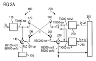
- the FIG. 2A shows an overview of an inventive arrangement 1 for determining a distance between a first station 100 and a second station 200.
- the series TX100-ser is emitted via an antenna 120 of the first station 100 and received after a transit time ⁇ from an antenna 260 of the second station 200.
- ⁇ indicates the period of time that a signal takes to travel from the first station 100 to the second station 200 or vice versa.
- the series TX100-ser is fed to a mixer 140 of the first station 100.
- the second station 200 has a PLL 210, which drives a first 220 and a second pulse generator 230 of the second station 200.
- the first pulses TX200-pulsP (0) and TX200-pulsM (0) of the two corresponding series are generated with a specific and known time interval to each other, ideally simultaneously. That is, the pulses TX200-pulsP (0) and TX200-pulsM (0) occur simultaneously and are also simultaneously broadcast as described below and simultaneously received at the first station 100.
- the second pulses TX200-pulsP (1) and TX200-pulsM (1) this simultaneity is no longer possible due to the different pulse repetition rates of the TX200-serP and TX200-serM series.
- f2 and f3 must have the same phase position in the second station 200 with respect to f1.
- the second station 200 synchronizes with the first station 100 by first receiving the pulse train REC200-ser received from the first station 100, which corresponds to a pulse offset TX100-ser emitted by the first station 100, first to a correlator 270, eg a mixer is supplied.
- the correlator 270 also receives the series TX200-serP generated in the first pulse generator 220 and the series TX200-serM generated in the second pulse generator 230.
- BB200-serM are generated, wherein BB200-serP (or BB200-serM) has a pulse when a pulse from TX200-serP (or TX200-serM) with a pulse of REC200 time this coincides.
- the signal pulse train TX100-ser emitted by the first station 100 is thus received in the second station 200, by supplying the received signal REC200-ser to a correlator 270 in which it is correlated with the pulse trains of the second station TX200-serP and TX200-serM, respectively.
- the regulation of f2 and f3 is done in such a way that the correlating series BB200-serP and BB200-serM coincide.
- the series TX200-serM and TX200-serP generated in the pulse generators 220, 230 are supplied to the antenna 240 of the second station 200 and radiated therefrom.
- the two series TX200-serM and TX200-serP are initially simply superimposed on one another in principle, i. They are added, for example, with the aid of the corresponding electronic means known to the person skilled in the art.
- the resulting series TX200-ser which is then emitted, accordingly consists of a large number of pulses, which, however, have no fixed pulse repetition rate.
- the emitted series TX200-ser of the second station 200 is received by an antenna 130 of the first station 100 after the transit time ⁇ .
- the received series REC100-ser is fed to the mixer 140 where it is correlated with the series TX100-ser of the pulse generator 110 of the first station 100.
- the series BB100-ser is finally fed to an evaluation unit 150, in which a time interval ⁇ between two successive signal pulses of the resulting series BB100-ser can be determined.
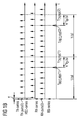
- FIG. 2B the timing of the various pulse trains TX100-ser, REC200-ser, TX200-serP, TX200-serM, BB200-ser, REC100-serP, REC100-serM, BB100-serP and BB100-serM is shown. Also in the FIG. 2B the respective pulse repetition rates of the different series are noted. The two individual TX200-serP and TX200-serM series combined into the TX200-ser series are shown separately from each other.
- REC100-serP and REC100-serM series would also be presented which would be received by the antenna 130 if TX200-serP and TX200-serM were actually transmitted separately.
- series BB100-serP and BB100-serM which would be generated in mixer 140, would be represented if TX200-serP and TX200-serM were separately transmitted and received.
- BB100-serM would result from the correlation of REC100-serM with TX100-ser.
- n o can hold.
- ⁇ 2 * ⁇ * f0 / ⁇ f
- i. ⁇ is proportional to the transit time ⁇ and thus proportional to the spatial distance between the first station 100 and the second station 200.
- a possible source of error in determining the correct transit time ⁇ can basically be that, for example, the time interval ⁇ between a pulse BB100-pulsM (n) and a pulse BB100-pulsP (o) with n ⁇ o is determined.
- the correct distance value from ⁇ and ⁇ ' can be easily selected by the fact that it is clear from the technical circumstances that only the value can be the correct value.
- pulse repetition rates do not correspond to the real conditions.
- the selection of the correct, ie smaller pulse spacing would therefore be simple and clear.
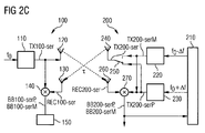
- the switch 250 is controlled in such a way that alternately a group of pulses of the one and the other series TX200-serM and TX200-serP is respectively transmitted.
- the number of pulses that belong to a group is calculated must be set so that the pulse series BB100-serM and BB100-serP resulting from the correlation in the first station 100 exist.
- the switch is controlled to switch at the time when the pulses of the second series TX200-serP and the third series TX200-serM are simultaneously generated.
- the second series TX200-serP is transmitted after the synchronous correlation signals BB200-serP and BB200-serM generated in the mixer 270, and TX200-serM before the correlation signals BB200-serP and BB200-serM.
- TX200-serM and TX200-serP series are of course also conceivable.
- the individual pulses of the two series can be detected by means of a corresponding switch 250 (see Figure 2C ) are radiated alternately via the antenna 240.
Landscapes
- Engineering & Computer Science (AREA)
- Radar, Positioning & Navigation (AREA)
- Remote Sensing (AREA)
- Computer Networks & Wireless Communication (AREA)
- Physics & Mathematics (AREA)
- General Physics & Mathematics (AREA)
- Signal Processing (AREA)
- Radar Systems Or Details Thereof (AREA)
Claims (12)
- Procédé pour déterminer le temps de propagation de signaux τ entre une première station (100) et une deuxième station (200), selon lequel :- une première série (TX100-ser) de premières impulsions de signaux est générée dans la première station (100) avec un premier taux de répétition des impulsions f1;- dans la deuxième station (200) sont générées une deuxième série (TX200-serP) de deuxièmes impulsions de signaux avec un deuxième taux de répétition des impulsions f2 et une troisième série (TX200-serM) de troisièmes impulsions de signaux avec un troisième taux de répétition des impulsions f3, avec f2 = f1 + Δf et f3 = f1 - Δf pour les taux de répétition des impulsions dans la deuxième station (200) ;- la deuxième série (TX200-serP) et la troisième série (TX200-serM) sont transmises de la deuxième station (200) à la première station (100) où elles sont reçues ;- les séries (REC100-serP, REC100-serM) reçues au niveau de la première station (100) sont envoyées sur un corrélateur (140), et plus particulièrement sur un mélangeur, et sont corrélées avec la première série (TX100-ser) dans le corrélateur (140), une série résultante (BB100-ser) d'impulsions de signaux étant générée ; et- le temps de propagation des signaux τ est déterminé à partir de la distance temporelle Δ entre deux impulsions de signaux successives de la série résultante (BB100-ser).
- Procédé selon la revendication 1, caractérisé en ce qu'est respectivement générée, dans le corrélateur (140), une impulsion de signal de la série résultante (BB100-ser) lorsqu'une impulsion de signal de la première série (TX100-ser) coïncide temporellement avec une impulsion de signal des séries reçues (REC100-serP, REC100-serM).
- Procédé selon la revendication 1 ou 2, caractérisé en ce que la deuxième série (TX200-serP) et la troisième série (TX200-serM) sont tout d'abord superposées à une autre série (TX200-ser) dans la deuxième station (200), notamment par addition de la deuxième série (TX200-serP) et de la troisième série (TX200-serM), et en ce que la deuxième série (TX200-serP) et la troisième série (TX200-serM) sont ensuite transmises sous la forme de l'autre série (TX200-ser) à la première station (100) et y sont reçues.
- Procédé selon la revendication 1 ou 2, caractérisé en ce que la deuxième série (TX200-serP) et la troisième série (TX200-serM) sont envoyées sur un commutateur (250) de la deuxième station (200) avant la transmission à la première station (100), le commutateur (250) étant commandé de manière telle qu'il sélectionne alternativement la deuxième série (TX200-serP) ou la troisième série (TX200-serM), et en ce que la série sélectionnée est transmise à la première station (100) et y est reçue.
- Procédé selon la revendication 4, caractérisé en ce que le commutateur (250) est commandé de manière telle qu'il commute respectivement à l'instant où sont générées simultanément les impulsions de la deuxième série (TX200-serP) et de la troisième série (TX200-serM).
- Procédé selon l'une des revendications précédentes, caractérisé en ce que la deuxième série (TX200-serP) et la troisième série (TX200-serM) sont générées avec une relation de phase fixe entre elles.
- Procédé selon l'une des revendications précédentes, caractérisé en ce que le deuxième taux de répétition des impulsions f2 et le troisième taux de répétition des impulsions f3 sont réglés par une boucle de réglage de phase (210) de la deuxième station (200).
- Procédé selon la revendication 7, caractérisé en ce que :- la deuxième série (TX200-serP) est générée par un générateur d'impulsions (220), le générateur d'impulsions (220) étant réglé de manière telle par la boucle de réglage de phase (210) que la deuxième série (TX200-serP) présente le deuxième taux de répétition des impulsions f2 et/ou- la troisième série (TX200-serM) est générée par un générateur d'impulsions (230), le générateur d'impulsions (230) étant réglé de manière telle par la boucle de réglage de phase (210) que la troisième série (TX200-serM) présente le troisième taux de répétition des impulsions f3.
- Procédé selon la revendication 7 ou 8, caractérisé en ce que :- la première série (TX100-ser) est transmise de la première station (100) à la deuxième station (200) et y est reçue ;- la série (REC200-ser) reçue au niveau de la deuxième station (200) est envoyée sur un corrélateur (270) de la deuxième station (200) où la série reçue (REC200-ser) est corrélée avec la deuxième série (TX200-serP) ou avec la troisième série (TX200-serM), un signal (BB200-ser) étant généré ; et- le signal (BB200-sig) est envoyé sur la boucle de réglage de phase (210) ; et- la boucle de réglage de phase (210), de son côté, met à disposition, sur la base du signal (BB200-sig), le deuxième taux de répétition des impulsions f2 et le troisième taux de répétition des impulsions f3.
- Agencement pour déterminer le temps de propagation de signaux τ entre une première station (100) et une deuxième station (200), selon lequel :- la première station (100) comporte un premier générateur d'impulsions (110) qui permet de générer une première série (TX100-ser) de premières impulsions de signaux avec un premier taux de répétition des impulsions f1 ;- la deuxième station (200) comporte au moins un autre générateur d'impulsions (220, 230), l'autre générateur d'impulsions (220, 230) permettant de générer une deuxième série (TX200-serP) de deuxièmes impulsions de signaux avec un deuxième taux de répétition des impulsions f2 et une troisième série (TX200-serM) de troisièmes impulsions de signaux avec un troisième taux de répétition des impulsions f3, avec f2 = f1 + Δf et f3 = f1 - Δf pour les taux de répétition des impulsions ;- la deuxième station (200) comporte un dispositif émetteur (240) pour la transmission de la deuxième série (TX200-serP) et de la troisième série (TX200-serM) à la première station (100) ;- la première station (100) comporte un dispositif récepteur (130) pour recevoir les séries émises et un corrélateur (140) pour corréler les séries reçues (REC100-serP, REC100-serM) avec la première série (TX100-ser), une série résultante (BB100-ser) étant générée lors de la corrélation ; et- la première station (100) comporte une unité d'évaluation (150) qui permet de déterminer une distance temporelle Δ entre deux impulsions de signaux successives (BB100-pulsM(n), BB100-pulsP(o) ; n,o = 0, 1, 2, 3, ... ; n = o) de la série résultante (BB100-ser).
- Agencement selon la revendication 10, caractérisé en ce que la deuxième station (200) comporte un commutateur (250) qui est relié à l'autre générateur d'impulsions (220, 230) et au dispositif émetteur (240) et qui est conçu pour sélectionner la deuxième série (TX200-serP) ou la troisième série (TX200-serM) pour transmission à la première station (100).
- Agencement selon la revendication 9 ou 10, caractérisé en ce que :- la première station (100) comporte un dispositif émetteur (120) pour transmettre la première série (TX100-ser) à la deuxième station (200) ;- la deuxième station (200) comporte un dispositif récepteur (260) pour recevoir la première série émise (TX100-ser) ainsi qu'un corrélateur (270) pour corréler la première série reçue (REC200-ser) avec la deuxième série (TX200-serP) et/ou avec la troisième série (TX200-serM), un signal (BB200-serP, BB200-serM) étant généré lors de la corrélation ; et- la deuxième station (200) comporte une boucle de réglage de phase (210) sur laquelle le signal (BB200-serP, BB200-serM) est envoyé et qui règle l'autre générateur d'impulsions (220, 230) sur la base du signal (BB200-serP, BB200-serM).
Applications Claiming Priority (2)
| Application Number | Priority Date | Filing Date | Title |
|---|---|---|---|
| DE102009036937A DE102009036937A1 (de) | 2009-08-11 | 2009-08-11 | Verfahren und Anordnung zur Laufzeitmessung eines Signals zwischen zwei Stationen der Anordnung |
| PCT/EP2010/060014 WO2011018286A1 (fr) | 2009-08-11 | 2010-07-13 | Procédé et agencement pour la mesure de la durée de propagation d'un signal entre deux stations de l'agencement |
Publications (2)
| Publication Number | Publication Date |
|---|---|
| EP2465310A1 EP2465310A1 (fr) | 2012-06-20 |
| EP2465310B1 true EP2465310B1 (fr) | 2013-12-04 |
Family
ID=43048969
Family Applications (1)
| Application Number | Title | Priority Date | Filing Date |
|---|---|---|---|
| EP10732942.7A Not-in-force EP2465310B1 (fr) | 2009-08-11 | 2010-07-13 | Procédé et agencement pour la mesure de la durée de propagation d'un signal entre deux stations de l'agencement |
Country Status (4)
| Country | Link |
|---|---|
| US (1) | US8742978B2 (fr) |
| EP (1) | EP2465310B1 (fr) |
| DE (1) | DE102009036937A1 (fr) |
| WO (1) | WO2011018286A1 (fr) |
Cited By (1)
| Publication number | Priority date | Publication date | Assignee | Title |
|---|---|---|---|---|
| US20120147940A1 (en) * | 2009-08-11 | 2012-06-14 | Siemens Aktiengesellschaft | Method and Arrangement for Measuring Delay of a Signal Between Two Stations of the Arrangement |
Families Citing this family (2)
| Publication number | Priority date | Publication date | Assignee | Title |
|---|---|---|---|---|
| US9172424B2 (en) * | 2014-03-04 | 2015-10-27 | Qualcomm Incorporated | Network self-synchronization using ultra wide band (UWB) impulse radio (IR) pulse train with unique repetition rates |
| US9709433B2 (en) * | 2014-06-30 | 2017-07-18 | Rosemount Tank Radar Ab | Pulsed radar level gauging with efficient start-up |
Family Cites Families (11)
| Publication number | Priority date | Publication date | Assignee | Title |
|---|---|---|---|---|
| US4106019A (en) * | 1972-10-05 | 1978-08-08 | Hughes Aircraft Company | Range resolving doppler radar system |
| US4628312A (en) * | 1983-10-19 | 1986-12-09 | Vega Precision Laboratories, Inc. | Decoding apparatus and method for a position coded pulse communication system |
| US4847622A (en) * | 1988-02-26 | 1989-07-11 | Electronique Serge Dassault | Coherent pulse radars |
| EP0676650B1 (fr) * | 1994-04-06 | 2002-01-30 | EADS Deutschland Gmbh | Méthode de mesure de distance à l'aide d'une liaison radio, et appareil de mise en oeuvre de la méthode |
| US6111536A (en) | 1998-05-26 | 2000-08-29 | Time Domain Corporation | System and method for distance measurement by inphase and quadrature signals in a radio system |
| US6639546B1 (en) * | 2001-11-06 | 2003-10-28 | Lockheed Martin Corporation | Radar system in which range ambiguity and range eclipsing are reduced by frequency diversity and alternation of pulse periodicity |
| DE10247718A1 (de) * | 2002-10-12 | 2004-04-22 | Conti Temic Microelectronic Gmbh | Verfahren zur Ermittlung des Abstands zwischen einer ersten und zweiten Sende-Empfangs-Station |
| DE102005021358A1 (de) * | 2005-05-04 | 2006-11-09 | Endress + Hauser Gmbh + Co. Kg | Laufzeitmessverfahren zur Ermittelung der Distanz |
| KR100780195B1 (ko) * | 2006-11-06 | 2007-11-27 | 삼성전기주식회사 | 펄스 신호의 오버랩 검출 장치, 방법 및 이를 포함하는거리 측정 장치 |
| DE102008025244A1 (de) * | 2008-05-27 | 2009-12-03 | Siemens Aktiengesellschaft | Verfahren zur funkbasierten Abstandmessung |
| DE102009036937A1 (de) * | 2009-08-11 | 2011-02-17 | Siemens Aktiengesellschaft | Verfahren und Anordnung zur Laufzeitmessung eines Signals zwischen zwei Stationen der Anordnung |
-
2009
- 2009-08-11 DE DE102009036937A patent/DE102009036937A1/de not_active Ceased
-
2010
- 2010-07-13 WO PCT/EP2010/060014 patent/WO2011018286A1/fr not_active Ceased
- 2010-07-13 EP EP10732942.7A patent/EP2465310B1/fr not_active Not-in-force
- 2010-07-13 US US13/390,077 patent/US8742978B2/en not_active Expired - Fee Related
Cited By (2)
| Publication number | Priority date | Publication date | Assignee | Title |
|---|---|---|---|---|
| US20120147940A1 (en) * | 2009-08-11 | 2012-06-14 | Siemens Aktiengesellschaft | Method and Arrangement for Measuring Delay of a Signal Between Two Stations of the Arrangement |
| US8742978B2 (en) * | 2009-08-11 | 2014-06-03 | Siemens Aktiengesellschaft | Method and arrangement for measuring delay of a signal between two stations of the arrangement |
Also Published As
| Publication number | Publication date |
|---|---|
| US20120147940A1 (en) | 2012-06-14 |
| US8742978B2 (en) | 2014-06-03 |
| DE102009036937A1 (de) | 2011-02-17 |
| EP2465310A1 (fr) | 2012-06-20 |
| WO2011018286A1 (fr) | 2011-02-17 |
Similar Documents
| Publication | Publication Date | Title |
|---|---|---|
| EP3014297B1 (fr) | Détecteur à radar fmcw à résolution angulaire | |
| EP3391070B1 (fr) | Système et procédé comprenant au moins trois stations recevant des signaux | |
| EP2041599B1 (fr) | Système radar | |
| EP3123199B1 (fr) | Procédé mis en oeuvre dans un système de radar, système de radar et dispositif d'un système de radar | |
| EP2755045B1 (fr) | Procédé de mesure cyclique de distances et de vitesses d'objets à l'aide d'un détecteur radar à onde continue à fréquence modulée (FMCW) | |
| WO2017084661A1 (fr) | Système radar à émission série et réception parallèle imbriquées | |
| DE2410500A1 (de) | Radarsystem mit hohem entfernungsaufloesungsvermoegen | |
| DE10157931A1 (de) | Verfahren und Vorrichtungen zur Synchronisation von Funkstationen und zeitsynchrones Funkbussystem | |
| DE102009050796B4 (de) | Verfahren und Anordnung zur Messung der Signallaufzeit zwischen einem Sender und einem Empfänger | |
| DE102012212888A1 (de) | Detektion von Radarobjekten mit einem Radarsensor eines Kraftfahrzeugs | |
| EP1490707A1 (fr) | Dispositif notamment destine a des applications radar bistatiques | |
| DE102012211809A1 (de) | Verfahren und Anordnung zur relativen Lageerkennung von Stationen mittels Funkortung | |
| EP3639549B1 (fr) | Procédé pour des applications de mesure radio | |
| DE112005003895B4 (de) | Verfahren zur Synchronisation von Takteinrichtungen | |
| DE3041465A1 (en) | A method in a tracking radar to attain a large unambiguous range for detected targets by means of radar pulses with high repetition frequency | |
| DE102011120244A1 (de) | Empfängerarchitektur für orthogonale, Multiple-Input-Multiple-Output Radarsysteme | |
| DE102006038857A1 (de) | Funksender | |
| EP2465310B1 (fr) | Procédé et agencement pour la mesure de la durée de propagation d'un signal entre deux stations de l'agencement | |
| AT506707B1 (de) | Vorrichtung zur berührungslosen abstandsmessung zwischen zwei messstellen | |
| EP3523671B1 (fr) | Procédé et dispositif de détermination de position | |
| EP4732038A1 (fr) | Réseau de capteurs radar et procédé de détermination de la vitesse relative d'une cible radar | |
| WO2008071457A1 (fr) | Procédé et système de détermination d'une position | |
| DE102004044330A1 (de) | Verfahren und Vorrichtung zur Entfernungs- und Geschwindigkeitsmessung | |
| EP2551697B1 (fr) | Procédé de detection d'une variation d'un détecteur de présence ou de mouvements associé à une zone de surveillance | |
| EP1986021B1 (fr) | Procédé et dispositif destinés à la détermination de la vitesse relative d'objets |
Legal Events
| Date | Code | Title | Description |
|---|---|---|---|
| PUAI | Public reference made under article 153(3) epc to a published international application that has entered the european phase |
Free format text: ORIGINAL CODE: 0009012 |
|
| 17P | Request for examination filed |
Effective date: 20120130 |
|
| AK | Designated contracting states |
Kind code of ref document: A1 Designated state(s): AL AT BE BG CH CY CZ DE DK EE ES FI FR GB GR HR HU IE IS IT LI LT LU LV MC MK MT NL NO PL PT RO SE SI SK SM TR |
|
| DAX | Request for extension of the european patent (deleted) | ||
| RAP1 | Party data changed (applicant data changed or rights of an application transferred) |
Owner name: SIEMENS AKTIENGESELLSCHAFT |
|
| GRAP | Despatch of communication of intention to grant a patent |
Free format text: ORIGINAL CODE: EPIDOSNIGR1 |
|
| INTG | Intention to grant announced |
Effective date: 20130702 |
|
| GRAS | Grant fee paid |
Free format text: ORIGINAL CODE: EPIDOSNIGR3 |
|
| GRAA | (expected) grant |
Free format text: ORIGINAL CODE: 0009210 |
|
| AK | Designated contracting states |
Kind code of ref document: B1 Designated state(s): AL AT BE BG CH CY CZ DE DK EE ES FI FR GB GR HR HU IE IS IT LI LT LU LV MC MK MT NL NO PL PT RO SE SI SK SM TR |
|
| REG | Reference to a national code |
Ref country code: GB Ref legal event code: FG4D Free format text: NOT ENGLISH |
|
| REG | Reference to a national code |
Ref country code: CH Ref legal event code: EP |
|
| REG | Reference to a national code |
Ref country code: IE Ref legal event code: FG4D Free format text: LANGUAGE OF EP DOCUMENT: GERMAN Ref country code: AT Ref legal event code: REF Ref document number: 643954 Country of ref document: AT Kind code of ref document: T Effective date: 20140115 |
|
| REG | Reference to a national code |
Ref country code: DE Ref legal event code: R096 Ref document number: 502010005560 Country of ref document: DE Effective date: 20140130 |
|
| REG | Reference to a national code |
Ref country code: NL Ref legal event code: VDEP Effective date: 20131204 |
|
| PG25 | Lapsed in a contracting state [announced via postgrant information from national office to epo] |
Ref country code: HR Free format text: LAPSE BECAUSE OF FAILURE TO SUBMIT A TRANSLATION OF THE DESCRIPTION OR TO PAY THE FEE WITHIN THE PRESCRIBED TIME-LIMIT Effective date: 20131204 Ref country code: NO Free format text: LAPSE BECAUSE OF FAILURE TO SUBMIT A TRANSLATION OF THE DESCRIPTION OR TO PAY THE FEE WITHIN THE PRESCRIBED TIME-LIMIT Effective date: 20140304 Ref country code: LT Free format text: LAPSE BECAUSE OF FAILURE TO SUBMIT A TRANSLATION OF THE DESCRIPTION OR TO PAY THE FEE WITHIN THE PRESCRIBED TIME-LIMIT Effective date: 20131204 Ref country code: SE Free format text: LAPSE BECAUSE OF FAILURE TO SUBMIT A TRANSLATION OF THE DESCRIPTION OR TO PAY THE FEE WITHIN THE PRESCRIBED TIME-LIMIT Effective date: 20131204 Ref country code: NL Free format text: LAPSE BECAUSE OF FAILURE TO SUBMIT A TRANSLATION OF THE DESCRIPTION OR TO PAY THE FEE WITHIN THE PRESCRIBED TIME-LIMIT Effective date: 20131204 Ref country code: FI Free format text: LAPSE BECAUSE OF FAILURE TO SUBMIT A TRANSLATION OF THE DESCRIPTION OR TO PAY THE FEE WITHIN THE PRESCRIBED TIME-LIMIT Effective date: 20131204 |
|
| REG | Reference to a national code |
Ref country code: LT Ref legal event code: MG4D |
|
| PG25 | Lapsed in a contracting state [announced via postgrant information from national office to epo] |
Ref country code: CY Free format text: LAPSE BECAUSE OF FAILURE TO SUBMIT A TRANSLATION OF THE DESCRIPTION OR TO PAY THE FEE WITHIN THE PRESCRIBED TIME-LIMIT Effective date: 20131204 Ref country code: LV Free format text: LAPSE BECAUSE OF FAILURE TO SUBMIT A TRANSLATION OF THE DESCRIPTION OR TO PAY THE FEE WITHIN THE PRESCRIBED TIME-LIMIT Effective date: 20131204 |
|
| PG25 | Lapsed in a contracting state [announced via postgrant information from national office to epo] |
Ref country code: IS Free format text: LAPSE BECAUSE OF FAILURE TO SUBMIT A TRANSLATION OF THE DESCRIPTION OR TO PAY THE FEE WITHIN THE PRESCRIBED TIME-LIMIT Effective date: 20140404 Ref country code: EE Free format text: LAPSE BECAUSE OF FAILURE TO SUBMIT A TRANSLATION OF THE DESCRIPTION OR TO PAY THE FEE WITHIN THE PRESCRIBED TIME-LIMIT Effective date: 20131204 |
|
| PG25 | Lapsed in a contracting state [announced via postgrant information from national office to epo] |
Ref country code: SK Free format text: LAPSE BECAUSE OF FAILURE TO SUBMIT A TRANSLATION OF THE DESCRIPTION OR TO PAY THE FEE WITHIN THE PRESCRIBED TIME-LIMIT Effective date: 20131204 Ref country code: RO Free format text: LAPSE BECAUSE OF FAILURE TO SUBMIT A TRANSLATION OF THE DESCRIPTION OR TO PAY THE FEE WITHIN THE PRESCRIBED TIME-LIMIT Effective date: 20131204 Ref country code: ES Free format text: LAPSE BECAUSE OF FAILURE TO SUBMIT A TRANSLATION OF THE DESCRIPTION OR TO PAY THE FEE WITHIN THE PRESCRIBED TIME-LIMIT Effective date: 20131204 Ref country code: PL Free format text: LAPSE BECAUSE OF FAILURE TO SUBMIT A TRANSLATION OF THE DESCRIPTION OR TO PAY THE FEE WITHIN THE PRESCRIBED TIME-LIMIT Effective date: 20131204 Ref country code: PT Free format text: LAPSE BECAUSE OF FAILURE TO SUBMIT A TRANSLATION OF THE DESCRIPTION OR TO PAY THE FEE WITHIN THE PRESCRIBED TIME-LIMIT Effective date: 20140404 Ref country code: CZ Free format text: LAPSE BECAUSE OF FAILURE TO SUBMIT A TRANSLATION OF THE DESCRIPTION OR TO PAY THE FEE WITHIN THE PRESCRIBED TIME-LIMIT Effective date: 20131204 |
|
| REG | Reference to a national code |
Ref country code: DE Ref legal event code: R097 Ref document number: 502010005560 Country of ref document: DE |
|
| PLBE | No opposition filed within time limit |
Free format text: ORIGINAL CODE: 0009261 |
|
| STAA | Information on the status of an ep patent application or granted ep patent |
Free format text: STATUS: NO OPPOSITION FILED WITHIN TIME LIMIT |
|
| PG25 | Lapsed in a contracting state [announced via postgrant information from national office to epo] |
Ref country code: DK Free format text: LAPSE BECAUSE OF FAILURE TO SUBMIT A TRANSLATION OF THE DESCRIPTION OR TO PAY THE FEE WITHIN THE PRESCRIBED TIME-LIMIT Effective date: 20131204 |
|
| 26N | No opposition filed |
Effective date: 20140905 |
|
| REG | Reference to a national code |
Ref country code: DE Ref legal event code: R097 Ref document number: 502010005560 Country of ref document: DE Effective date: 20140905 |
|
| PG25 | Lapsed in a contracting state [announced via postgrant information from national office to epo] |
Ref country code: LU Free format text: LAPSE BECAUSE OF FAILURE TO SUBMIT A TRANSLATION OF THE DESCRIPTION OR TO PAY THE FEE WITHIN THE PRESCRIBED TIME-LIMIT Effective date: 20140713 Ref country code: SI Free format text: LAPSE BECAUSE OF FAILURE TO SUBMIT A TRANSLATION OF THE DESCRIPTION OR TO PAY THE FEE WITHIN THE PRESCRIBED TIME-LIMIT Effective date: 20131204 |
|
| REG | Reference to a national code |
Ref country code: CH Ref legal event code: PL |
|
| REG | Reference to a national code |
Ref country code: IE Ref legal event code: MM4A |
|
| PG25 | Lapsed in a contracting state [announced via postgrant information from national office to epo] |
Ref country code: LI Free format text: LAPSE BECAUSE OF NON-PAYMENT OF DUE FEES Effective date: 20140731 Ref country code: CH Free format text: LAPSE BECAUSE OF NON-PAYMENT OF DUE FEES Effective date: 20140731 |
|
| PG25 | Lapsed in a contracting state [announced via postgrant information from national office to epo] |
Ref country code: IE Free format text: LAPSE BECAUSE OF NON-PAYMENT OF DUE FEES Effective date: 20140713 |
|
| PG25 | Lapsed in a contracting state [announced via postgrant information from national office to epo] |
Ref country code: SM Free format text: LAPSE BECAUSE OF FAILURE TO SUBMIT A TRANSLATION OF THE DESCRIPTION OR TO PAY THE FEE WITHIN THE PRESCRIBED TIME-LIMIT Effective date: 20131204 Ref country code: MC Free format text: LAPSE BECAUSE OF FAILURE TO SUBMIT A TRANSLATION OF THE DESCRIPTION OR TO PAY THE FEE WITHIN THE PRESCRIBED TIME-LIMIT Effective date: 20131204 |
|
| PG25 | Lapsed in a contracting state [announced via postgrant information from national office to epo] |
Ref country code: BG Free format text: LAPSE BECAUSE OF FAILURE TO SUBMIT A TRANSLATION OF THE DESCRIPTION OR TO PAY THE FEE WITHIN THE PRESCRIBED TIME-LIMIT Effective date: 20131204 Ref country code: MT Free format text: LAPSE BECAUSE OF FAILURE TO SUBMIT A TRANSLATION OF THE DESCRIPTION OR TO PAY THE FEE WITHIN THE PRESCRIBED TIME-LIMIT Effective date: 20131204 Ref country code: GR Free format text: LAPSE BECAUSE OF FAILURE TO SUBMIT A TRANSLATION OF THE DESCRIPTION OR TO PAY THE FEE WITHIN THE PRESCRIBED TIME-LIMIT Effective date: 20140305 |
|
| REG | Reference to a national code |
Ref country code: FR Ref legal event code: PLFP Year of fee payment: 7 |
|
| PG25 | Lapsed in a contracting state [announced via postgrant information from national office to epo] |
Ref country code: HU Free format text: LAPSE BECAUSE OF FAILURE TO SUBMIT A TRANSLATION OF THE DESCRIPTION OR TO PAY THE FEE WITHIN THE PRESCRIBED TIME-LIMIT; INVALID AB INITIO Effective date: 20100713 Ref country code: TR Free format text: LAPSE BECAUSE OF FAILURE TO SUBMIT A TRANSLATION OF THE DESCRIPTION OR TO PAY THE FEE WITHIN THE PRESCRIBED TIME-LIMIT Effective date: 20131204 Ref country code: BE Free format text: LAPSE BECAUSE OF FAILURE TO SUBMIT A TRANSLATION OF THE DESCRIPTION OR TO PAY THE FEE WITHIN THE PRESCRIBED TIME-LIMIT Effective date: 20140731 |
|
| REG | Reference to a national code |
Ref country code: AT Ref legal event code: MM01 Ref document number: 643954 Country of ref document: AT Kind code of ref document: T Effective date: 20150713 |
|
| PGFP | Annual fee paid to national office [announced via postgrant information from national office to epo] |
Ref country code: IT Payment date: 20160727 Year of fee payment: 7 Ref country code: GB Payment date: 20160713 Year of fee payment: 7 Ref country code: DE Payment date: 20160920 Year of fee payment: 7 |
|
| PG25 | Lapsed in a contracting state [announced via postgrant information from national office to epo] |
Ref country code: AT Free format text: LAPSE BECAUSE OF NON-PAYMENT OF DUE FEES Effective date: 20150713 |
|
| PGFP | Annual fee paid to national office [announced via postgrant information from national office to epo] |
Ref country code: FR Payment date: 20160725 Year of fee payment: 7 |
|
| REG | Reference to a national code |
Ref country code: DE Ref legal event code: R119 Ref document number: 502010005560 Country of ref document: DE |
|
| GBPC | Gb: european patent ceased through non-payment of renewal fee |
Effective date: 20170713 |
|
| REG | Reference to a national code |
Ref country code: FR Ref legal event code: ST Effective date: 20180330 |
|
| PG25 | Lapsed in a contracting state [announced via postgrant information from national office to epo] |
Ref country code: GB Free format text: LAPSE BECAUSE OF NON-PAYMENT OF DUE FEES Effective date: 20170713 Ref country code: DE Free format text: LAPSE BECAUSE OF NON-PAYMENT OF DUE FEES Effective date: 20180201 |
|
| PG25 | Lapsed in a contracting state [announced via postgrant information from national office to epo] |
Ref country code: FR Free format text: LAPSE BECAUSE OF NON-PAYMENT OF DUE FEES Effective date: 20170731 |
|
| PG25 | Lapsed in a contracting state [announced via postgrant information from national office to epo] |
Ref country code: MK Free format text: LAPSE BECAUSE OF FAILURE TO SUBMIT A TRANSLATION OF THE DESCRIPTION OR TO PAY THE FEE WITHIN THE PRESCRIBED TIME-LIMIT Effective date: 20131204 |
|
| PG25 | Lapsed in a contracting state [announced via postgrant information from national office to epo] |
Ref country code: IT Free format text: LAPSE BECAUSE OF NON-PAYMENT OF DUE FEES Effective date: 20170713 |
|
| PG25 | Lapsed in a contracting state [announced via postgrant information from national office to epo] |
Ref country code: AL Free format text: LAPSE BECAUSE OF FAILURE TO SUBMIT A TRANSLATION OF THE DESCRIPTION OR TO PAY THE FEE WITHIN THE PRESCRIBED TIME-LIMIT Effective date: 20131204 |