EP2465571A2 - Implantierbares Gerät - Google Patents
Implantierbares Gerät Download PDFInfo
- Publication number
- EP2465571A2 EP2465571A2 EP11191741A EP11191741A EP2465571A2 EP 2465571 A2 EP2465571 A2 EP 2465571A2 EP 11191741 A EP11191741 A EP 11191741A EP 11191741 A EP11191741 A EP 11191741A EP 2465571 A2 EP2465571 A2 EP 2465571A2
- Authority
- EP
- European Patent Office
- Prior art keywords
- longitudinal section
- electrode
- medical device
- conductor
- line
- Prior art date
- Legal status (The legal status is an assumption and is not a legal conclusion. Google has not performed a legal analysis and makes no representation as to the accuracy of the status listed.)
- Granted
Links
- 239000004020 conductor Substances 0.000 claims abstract description 67
- 239000000463 material Substances 0.000 claims description 3
- 238000002560 therapeutic procedure Methods 0.000 claims description 3
- 238000001514 detection method Methods 0.000 claims description 2
- 210000001519 tissue Anatomy 0.000 description 14
- 238000010586 diagram Methods 0.000 description 12
- 238000005259 measurement Methods 0.000 description 9
- 230000000747 cardiac effect Effects 0.000 description 8
- 230000000638 stimulation Effects 0.000 description 6
- FAPWRFPIFSIZLT-UHFFFAOYSA-M Sodium chloride Chemical compound [Na+].[Cl-] FAPWRFPIFSIZLT-UHFFFAOYSA-M 0.000 description 4
- 238000004364 calculation method Methods 0.000 description 4
- 230000005684 electric field Effects 0.000 description 4
- 230000000694 effects Effects 0.000 description 3
- 238000002474 experimental method Methods 0.000 description 3
- 210000005003 heart tissue Anatomy 0.000 description 3
- 238000010438 heat treatment Methods 0.000 description 3
- 210000005241 right ventricle Anatomy 0.000 description 3
- 238000004088 simulation Methods 0.000 description 3
- 239000000243 solution Substances 0.000 description 3
- 230000009466 transformation Effects 0.000 description 3
- 230000002861 ventricular Effects 0.000 description 3
- 230000002238 attenuated effect Effects 0.000 description 2
- 238000005229 chemical vapour deposition Methods 0.000 description 2
- 230000007423 decrease Effects 0.000 description 2
- 230000001419 dependent effect Effects 0.000 description 2
- 239000003792 electrolyte Substances 0.000 description 2
- 230000002349 favourable effect Effects 0.000 description 2
- 230000004907 flux Effects 0.000 description 2
- 238000009413 insulation Methods 0.000 description 2
- 238000002595 magnetic resonance imaging Methods 0.000 description 2
- 210000004165 myocardium Anatomy 0.000 description 2
- 239000002504 physiological saline solution Substances 0.000 description 2
- 241000234282 Allium Species 0.000 description 1
- 235000002732 Allium cepa var. cepa Nutrition 0.000 description 1
- 241000935974 Paralichthys dentatus Species 0.000 description 1
- 229910000566 Platinum-iridium alloy Inorganic materials 0.000 description 1
- 238000002679 ablation Methods 0.000 description 1
- 230000006978 adaptation Effects 0.000 description 1
- 230000005540 biological transmission Effects 0.000 description 1
- 210000004556 brain Anatomy 0.000 description 1
- 230000008859 change Effects 0.000 description 1
- 239000011248 coating agent Substances 0.000 description 1
- 238000000576 coating method Methods 0.000 description 1
- 238000013016 damping Methods 0.000 description 1
- 238000009795 derivation Methods 0.000 description 1
- 238000003745 diagnosis Methods 0.000 description 1
- 230000009977 dual effect Effects 0.000 description 1
- 238000005516 engineering process Methods 0.000 description 1
- 239000011521 glass Substances 0.000 description 1
- 230000001939 inductive effect Effects 0.000 description 1
- 238000011835 investigation Methods 0.000 description 1
- 210000005240 left ventricle Anatomy 0.000 description 1
- 238000004519 manufacturing process Methods 0.000 description 1
- 229910052751 metal Inorganic materials 0.000 description 1
- 239000002184 metal Substances 0.000 description 1
- 210000005036 nerve Anatomy 0.000 description 1
- 210000000056 organ Anatomy 0.000 description 1
- 239000003973 paint Substances 0.000 description 1
- 230000000737 periodic effect Effects 0.000 description 1
- HWLDNSXPUQTBOD-UHFFFAOYSA-N platinum-iridium alloy Chemical class [Ir].[Pt] HWLDNSXPUQTBOD-UHFFFAOYSA-N 0.000 description 1
- 229920001296 polysiloxane Polymers 0.000 description 1
- 230000009467 reduction Effects 0.000 description 1
- 210000005245 right atrium Anatomy 0.000 description 1
- 230000000630 rising effect Effects 0.000 description 1
- 239000011780 sodium chloride Substances 0.000 description 1
- 238000012360 testing method Methods 0.000 description 1
- 238000012546 transfer Methods 0.000 description 1
- 238000007740 vapor deposition Methods 0.000 description 1
- XLYOFNOQVPJJNP-UHFFFAOYSA-N water Substances O XLYOFNOQVPJJNP-UHFFFAOYSA-N 0.000 description 1
Images



Classifications
-
- A—HUMAN NECESSITIES
- A61—MEDICAL OR VETERINARY SCIENCE; HYGIENE
- A61N—ELECTROTHERAPY; MAGNETOTHERAPY; RADIATION THERAPY; ULTRASOUND THERAPY
- A61N1/00—Electrotherapy; Circuits therefor
- A61N1/02—Details
- A61N1/04—Electrodes
- A61N1/05—Electrodes for implantation or insertion into the body, e.g. heart electrode
-
- A—HUMAN NECESSITIES
- A61—MEDICAL OR VETERINARY SCIENCE; HYGIENE
- A61B—DIAGNOSIS; SURGERY; IDENTIFICATION
- A61B18/00—Surgical instruments, devices or methods for transferring non-mechanical forms of energy to or from the body
- A61B18/04—Surgical instruments, devices or methods for transferring non-mechanical forms of energy to or from the body by heating
- A61B18/12—Surgical instruments, devices or methods for transferring non-mechanical forms of energy to or from the body by heating by passing a current through the tissue to be heated, e.g. high-frequency current
- A61B18/14—Probes or electrodes therefor
- A61B18/1492—Probes or electrodes therefor having a flexible, catheter-like structure, e.g. for heart ablation
-
- A—HUMAN NECESSITIES
- A61—MEDICAL OR VETERINARY SCIENCE; HYGIENE
- A61N—ELECTROTHERAPY; MAGNETOTHERAPY; RADIATION THERAPY; ULTRASOUND THERAPY
- A61N1/00—Electrotherapy; Circuits therefor
- A61N1/02—Details
- A61N1/04—Electrodes
- A61N1/05—Electrodes for implantation or insertion into the body, e.g. heart electrode
- A61N1/056—Transvascular endocardial electrode systems
-
- A—HUMAN NECESSITIES
- A61—MEDICAL OR VETERINARY SCIENCE; HYGIENE
- A61N—ELECTROTHERAPY; MAGNETOTHERAPY; RADIATION THERAPY; ULTRASOUND THERAPY
- A61N1/00—Electrotherapy; Circuits therefor
- A61N1/02—Details
- A61N1/08—Arrangements or circuits for monitoring, protecting, controlling or indicating
- A61N1/086—Magnetic resonance imaging [MRI] compatible leads
Definitions
- the invention relates to a permanently or temporarily implantable device with an elongated electrical conductor.
- Such devices for example, electrode lines for electrical stimulation, have the disadvantage that their electrical conductor can heat up in a magnetic resonance tomograph, because the prevailing magnetic resonance in the magnetic resonance field inducing magnetic currents in the electrical conductor not inconsiderable. Therefore, cardiac pacemaker patients today can usually not be examined or only to a limited extent in a magnetic resonance tomograph.
- implantable cardiac pacemakers or defibrillators typically have at least one pacing lead connected to their proximal end for connection to the pacemaker or defibrillator with a standard electrical connection and one or more electrode poles at their distal end provided for placement in the heart.
- Such an electrode pole serves to deliver electrical impulses to the tissue (myocardium) of the heart or to sense electric fields in order to be able to sense an activity of a heart within the scope of so-called sensing.
- Electrode poles are typically provided in the form of a ring around the electrode lead having an electrically conductive surface or in the form of a tip electrode at the distal end of the electrode lead.
- the electrode poles are electrically conductively connected via one or more electrical lines to contacts of the electrical connection of the electrode line at its proximal end.
- the electrode leads extend at the proximal end thereof and the electrode poles at the distal end of the electrode lead one or more electrical leads which carry one or more of the Electrically connect electrode poles to one or more of the contacts.
- These electrical lines can be used, on the one hand, to transmit stimulation pulses to the electrode poles or to transmit electrical signals picked up by the electrode poles to the proximal end of the electrode line and are referred to as function lines in the course of the further description.
- Such functional lines are required for the functions of the respective electrode line required electrical conductors and as such the risk that in them by external alternating magnetic fields electrical currents are induced, which can lead, for example, to an undesirable heating of the function lines or the associated electrode poles.
- the invention has for its object to provide a device which solves the problem described above.
- the electrical line of the medical device according to the invention contains a functional conductor, which has between its proximal end and a connected electrode pole line sections of preferably greatly different characteristic impedance. These attenuate and transform a contact resistance of the connected Elektrodenpols into the tissue such that a mismatch can be achieved for high frequency and thereby in the implanted state in the case of exposure to high-frequency magnetic alternating fields, as used in magnetic resonance imaging, which is transmitted to the tissue Performance is lowered. As a result, heating of the tissue, in particular near the electrode pole or optionally near the electrode poles, can be significantly reduced.
- the electrical lead is preferably an electrode lead for the diagnosis or therapy of cardiac activity.
- the difference between the first and second conduction wave resistance is so pronounced in embodiments of the medical device that a real part of the second conduction wave resistance for radio frequency electromagnetic waves is smaller by a factor of at least two than a real part of the first conduction wave resistance.
- this difference is even greater and the said factor is at least five, and in particularly preferred embodiments at least ten.
- the inventors Up to a length of the second longitudinal section of one-quarter of the inner conductor dielectric diameter, the inventors have found in experiments with weak attenuation by the outer conductor (the tissue) even an increase in the active power of a used in the experiment tip electrode of an electrode line.
- the effectiveness of the second longitudinal section for reducing the active power transmitted to the tissue then increases with increasing length of the second longitudinal section.
- Particularly favorable lengths of the second longitudinal section are in the range up to a maximum of 5 d iel .
- the second longitudinal section does not exceed a length of about 10 d.
- the effectiveness of the second length also depends on the degree of attenuation experienced by radio frequency waves in the transmission line. The higher the attenuation, the lower the active power at the electrode pole.
- the functional guide has an inner conductor and a hollow-cylindrical outer conductor, wherein the inner conductor has a different geometric shape in the second longitudinal section from the inner conductor in the first longitudinal section.
- the inner conductor is hollow-helical in the first longitudinal section of the electrical conductor and cylindrical in the second longitudinal section.
- the cylindrical second longitudinal section of the inner conductor has in this type of realization in a variant a larger diameter than the hollow helix of the inner conductor in the first longitudinal section. From the outer conductor, however, it should be separated by an inner dielectric, so be electrically isolated. This inner dielectric can be realized as a coating or film.
- layer thicknesses down to about 100 nm or even less are possible, e.g. by PVD (plasma vapor deposition) or CVD (chemical vapor deposition).
- PVD plasma vapor deposition
- CVD chemical vapor deposition
- a very thin layer is more susceptible to mechanical stress. It could e.g. rub off or lose their electrical isolatin property through scratches.
- Preferred as a compromise between electrical effect and mechanical stability is a layer thickness of 0.5 .mu.m to 2.5 .mu.m, particularly preferably 1 .mu.m.
- the inner conductor may alternatively be designed as a cable feed line in the first longitudinal section and in the form of a hollow helix in the second section.
- the invention applies to electrode leads of any type of electrode poles.
- the electrode pole can be designed, for example, as a tip electrode pole or as a ring electrode pole. There may also be several electrode poles on a function conductor be provided. In some embodiments, the electrode pole directly adjoins the second longitudinal section of the functional guide. This is manufacturing technology advantageous because the first longitudinal section does not have to be interrupted. However, in a variant, it is provided to embed the second longitudinal section in the function conductor at a distance from the electrode pole, so that the second longitudinal section is surrounded in both longitudinal directions by conductor sections of the type of the first longitudinal section.
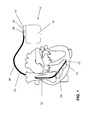
- FIG. 1 As an example of implantable medical devices, there is shown an implantable cardiac stimulator 10 and an implantable electrode lead 20 connected thereto.
- the implantable cardiac stimulator 10 may be a pacemaker or a cardioverter / defibrillator (ICD).
- the heart stimulator 10 is a ventricular pacemaker and defibrillator.
- Other known cardiac stimulators are dual chamber pacemakers for stimulation of the right atrium and right ventricle, or biventricular pacemakers, which can also stimulate the left ventricle in addition to the right ventricle.
- Such stimulators typically have a housing 12, which is usually made of metal and thus is electrically conductive and can serve as a large electrode pole.
- a terminal housing 14 is typically attached, which is also referred to as a header.
- Such a header typically has contact sockets for receiving plug contacts.
- the contact sockets have electrical contacts 16, which are connected via corresponding conductors with an arranged in the housing 12 of the heart stimulator 10 electronics.
- the electrode line 20 likewise constitutes an implantable medical device.
- electrode poles in the form of a tip or tip electrode 22 and a ring electrode 24 arranged in the vicinity thereof are arranged in a manner known per se.
- the electrode poles 22 and 24 are designed such that, depending on the function of a cardiac stimulator, to which the electrode lead 20 is connected, for sensing electrical potentials of the heart tissue (myocardium). serve or for the delivery of electrical signals, for example, for the delivery of stimulation pulses to the surrounding heart tissue, are formed.
- FIG. 1 shows how the electrode poles, so the tip electrode 22 and the ring electrode 24, in the application, the electrode line 20, located in the apex of a right ventricle of a heart.
- Both the tip electrode 22 and the ring electrode 24 are electrically connected via at least one electrical conductor 26 with a plug contact 28 at the proximal end of the electrode line 20.
- the plug contact 28 has electrical contacts which correspond to the electrical contacts 16 of the contact socket in the connection housing 14 of the implantable cardiac stimulator.
- the electrical conductors 26 may be formed in the electrode line 20 in different longitudinal sections as approximately elongated Seilzugleiter or as a helical coiled conductor.
- Such conductors which electrically connect functional electrode poles to electrical contacts of the plug-in contact at the proximal end of the electrode lead 20 are also referred to as function leads in the context of this text, since they transmit electrical signals from plug contact to the respective electrode pole or represent sensed electrical potentials, for example Lead signals from each electrode pole to the plug contact and thus serve the elementary function of the medical device.
- the electrical function conductors 26, which connect the electrode poles 22 and 24, respectively, to the electrical contacts of the plug 28 of the electrode line 20, are surrounded over most of their length by an insulating sheath, so that an electrical contact to the tissue of the heart is targeted via the electrode poles comes about.
- the electrode line 20 In addition to the electrode poles 22 and 24, which typically serve the (in this case, ventricular) stimulation of the heart tissue, the electrode line 20 also has two larger-area electrode poles 30 and 32, which serve as defibrillation electrodes and are formed by at least one bare helix-like coiled wire ,
- an ablation electrode lead can in principle also be used, which likewise projects into the heart of a patient in the case of application and which is controlled by a device arranged outside the patient and is connected thereto for this purpose.
- electrode lines can be used with customary adaptation to the special requirements of the respective field of application also for stimulation and derivation of signals to nerves, brain, and other organs or for the supply of implantable sensors.
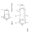
- FIG. 2 shows an equivalent circuit diagram of a functional conductor of an electrode lead according to the prior art.
- the function conductor 26 forms with its longitudinal extent L a first line impedance Z 0 .
- the electrode pole 22 forms a load line impedance Z L.
- a voltage U 0 is supplied at the proximal end of the functional conductor.
- a voltage U L drops at the distal end of the functional conductor.
- the functional conductor 26 now has the two longitudinal sections L1 and L2. Their aspect ratio to each other is in Figur3 not shown according to the actual ratio.
- the first longitudinal section L1 with a functional conductor section 26.1 is substantially longer than the second longitudinal section L2 with a functional conductor section 26.2.
- the second longitudinal section L2 has a length 1 and a line resistance Z 1 .
- a voltage U E Towards the proximal end of the functional conductor 26, at the beginning of the second longitudinal section, there is a voltage U E , and at the distal end of the functional conductor 26, in the present example also the end of the second longitudinal section L2, a voltage U A is applied across the load Line wave resistance of the electrode 22 at.
- U E , I E , U A and I A The voltages and currents, U E , I E , U A and I A , at the beginning and end of the second longitudinal section L2 can be divided into a traveling wave and a returning wave:
- the load line wave resistance Z L and a transformed load line wave resistance are calculated Z ⁇ L from the back and forth waves as follows:
- Z L Z 1 ⁇ U H + U R U H - U R
- Z ⁇ L Z 1 ⁇ U H ⁇ e jkl + U R ⁇ e - jkl U H ⁇ e jkl - U R ⁇ e - jkl
- Size symbols provided with a superscript designate the conjugate complexes of a respective number.
- the power at the load line impedance, ie in the electrode tip can be calculated from the back and forth wave.
- the measured values in the table indicate that the inductivity of the cable already plays an important role in measurements with an open head starting at frequencies of 500 kHz. From measurements with head in the air (interruption between inner and outer conductor, or between tip and ring), a value of the capacitance between inner and outer helix was determined to be 140 to 150 pF / m.
- the resistance lining of inside and outside spiral can be determined with head in the water at frequencies below 500kHz, if one subtracts the resistance between tip and ring.
- head in the saline solution that at higher frequency, the inductance of the line is increasingly affecting the measurement result and depending on Electrode type, here in the Setrox S40, from 1MHz frequency can even compensate for the capacity of the line.
- the measured resistance values are unaffected by the position of the electrode head to the counter electrode, when the two are more than about 4 centimeters apart. This suggests that the resistors RT, RR and RG are off FIG. 4 the resistances of the respective electrode pole are at an infinitely far point with zero potential.
- the resistances of the electrodes with each other were measured at the electrode cable BIOTRONIK Setrox S60 as follows Table 2 frequency Tip and ring against counter electrode Ring and counter electr. Against Tip Tip and counter electr. against ring 1MHz 77,7 ⁇ 137,6 ⁇ 156 ⁇ 1,64 ⁇ H 70nF 3,26 ⁇ H 500kHz 77,8 ⁇ 137,8 ⁇ 155,4 ⁇ 2,5 ⁇ H 0,22 ⁇ H 3,98 ⁇ H 200kHz 77,9 ⁇ 138,04 ⁇ Not measured 3,0 ⁇ H 1,44 ⁇ F 100kHz 78,2 ⁇ 138,48 ⁇ 154,77 ⁇ Not measurable 1,222 ⁇ F 3,41 ⁇ H 50kHz 78,538 ⁇ 139,22 ⁇ 154,86 ⁇ Not measurable 1,5 ⁇ F 3,49 ⁇ H 20kHz 79,026 ⁇ 140 ⁇ 155,20 ⁇ 9,11 ⁇ F 2,3 ⁇ F 28,27 ⁇ F
- the measured values for tip and ring vary by 1.2% (tip), or 2.7% (ring), the tolerance in the conductivity of the physiological saline varies by 6.2%, so that with deviations of 10% upward or below must be expected.
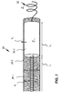
- FIG. 7 is a schematic representation of an example of a functional conductor of an electrode line.
- the embodiment can also be through the equivalent circuit of the FIG. 3 represent. Therefore, in FIG. 7 largely identical reference numerals as in FIG. 3 used.
- the functional conductor 26 has a first longitudinal section L1, not shown here in full length, in which its inner conductor is designed as a hollow helix 26.1 and has a first longitudinal section L1
- Line wave resistance Z 0 forms.
- first longitudinal section L1 comparatively very short second longitudinal section L2 of the functional guide 26 of the inner conductor is formed as a cylindrical conductor 26.2, for example, 2 millimeters in diameter and 10 millimeters in length, with an insulating layer, an inner dielectric (eg, a paint layer) of a thickness d2 of 10 Micrometer is surrounded.
- the hollow helix 26.1 has a significantly higher line resistance for electromagnetic radio frequency waves, as can be seen from the above in connection with the FIGS. 4 to 6 results in calculations and measurements.
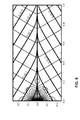
- FIG. 8 is a graph showing the result of a simulation calculation representing the electric field strength and magnetic flux tube magnetic field lines around a longitudinal section of 0 to 1 meter of a prior art elongated electric conductor, which is the equivalent circuit of FIG FIG. 2 corresponds and has an inner electrolyte diameter d iel of 2mm ..
- the thin lines are the field lines or flow tubes. They show the course of the field which forms around the cylindrical line extending on the abscissa of the diagram when a high frequency wave propagates in the plane of the drawing from left to right along the line.
- the ordinate plots the distance from the abscissa in meters between -0.25 and 0.25 meters. Negative distance values are as the distance in the opposite direction to the direction of positive distance values understand.
- the bold lines are isolines and encode the electromagnetic energy that is in the respective radius elements 2 ⁇ ⁇ d ⁇ .
- the electromagnetic energy is to be understood as energy averaged over time, so that it is not greatest at the places where the field lines are close together, but generally close to the line.
- the load resistance differs in its size not too much from the internal resistance, so that in this example 61% of the maximum possible active power is implemented.
- the magnetic field lines circling around the line in a cylinder-like manner and are exactly perpendicular to the electric field lines at each point. So this is the propagation of a transverse electromagnetic (TEM) wave.
- TEM transverse electromagnetic
- an insulated wire such as an electrode lead in body tissue, is a conduit on which a TEM wave can propagate.
- This line has a characteristic impedance, an attenuation and a wavelength, which are dependent on the frequency.
- the length of one of these onions is half a wavelength. You can read the expected wavelength of 23cm from the diagram.
- FIG. 9 shows for comparison a FIG. 8 corresponding graphical representation of the result of a further simulation calculation, the electric field strength and magnetic field lines or contour lines of magnetic flux tubes around a longitudinal section from 0 to 1 meter of an elongated electrical conductor according to the embodiment of FIG. 7 reproduces.
- an electrode line at the frequency 64MHz also has a strong attenuation.
- the energy at the right-hand part of the diagram, that is to say towards the distal end of the line, is markedly lower than in the case of the electrode line according to the prior art, whose values in FIG Figur8 are shown.
- FIG. 10 shows that over the length of the line occur periodic variations in the ratios of the performance parameters apparent power, reactive power and active power. Over the length of 0 centimeters (proximal end) to 20 centimeters, a damping is visible over 7 periods.
- the length of the inserted line piece is plotted on the abscissa and the respective power ratio on the load resistance of the electrode tip on the ordinate. It can be seen from the initially rising over a length of almost 2 millimeters curves of the active power and the pigtail that the short line piece to reduce the performance parameters should be longer than 2 millimeters. Because up to a length of about 0.5 millimeters, the ratio of the active power with the additional line piece to the active power without the additional line piece at the electrode tip even increases because of the transformation properties. With a 1 cm long line piece, the power in the electrode tip is already reduced to about half.
Landscapes
- Health & Medical Sciences (AREA)
- Heart & Thoracic Surgery (AREA)
- Life Sciences & Earth Sciences (AREA)
- Engineering & Computer Science (AREA)
- Nuclear Medicine, Radiotherapy & Molecular Imaging (AREA)
- Animal Behavior & Ethology (AREA)
- Veterinary Medicine (AREA)
- Public Health (AREA)
- General Health & Medical Sciences (AREA)
- Biomedical Technology (AREA)
- Cardiology (AREA)
- Radiology & Medical Imaging (AREA)
- Surgery (AREA)
- Medical Informatics (AREA)
- Molecular Biology (AREA)
- Plasma & Fusion (AREA)
- Physics & Mathematics (AREA)
- Otolaryngology (AREA)
- Vascular Medicine (AREA)
- Electrotherapy Devices (AREA)
- Neurology (AREA)
Abstract
Description
- Die Erfindung betrifft ein permanent oder temporär implantierbares Gerät mit einem langgestreckten elektrischen Leiter.
- Solche Geräte, beispielsweise Elektrodenleitungen für die Elektrostimulation, haben den Nachteil, dass sich ihr elektrischer Leiter in einem Kernspintomografen erwärmen kann, weil die im Kernspintomografen herrschenden wechselnden Magnetfelder in dem elektrischen Leiter nicht unbeachtliche elektrische Ströme induzieren. Deshalb können Herzschrittmacherpatienten heutzutage in der Regel nicht oder nur eingeschränkt in einem Kernspintomografen untersucht werden.
- An implantierbaren Herzschrittmachern oder Defibrillatoren sind nämlich typischerweise wenigstens eine Stimulationselektrodenleitung angeschlossen, die an ihrem proximalen, zum Anschluss an den Herzschrittmacher oder Defibrillator vorgesehenen Ende einen standardisierten elektrischen Anschluss aufweist und an ihrem distalen, zur Platzierung im Herzen vorgesehenen Ende einen oder mehrere Elektrodenpole aufweist. Ein solcher Elektrodenpol dient zur Abgabe elektrischer Impulse an das Gewebe (Myokard) des Herzens oder zum Abfühlen elektrischer Felder, um im Rahmen des sogenannten Sensings eine Aktivität eines Herzens abfühlen zu können. Elektrodenpole sind typischerweise in Form eines Rings um die Elektrodenleitung mit einer elektrisch leitenden Oberfläche oder in Form einer Spitzen- oder Tipelektrode am distalen Ende der Elektrodenleitung vorgesehen. Die Elektrodenpole sind über eine oder mehrere elektrische Leitungen mit Kontakten des elektrischen Anschlusses der Elektrodenleitung an deren proximalem Ende elektrisch leitend verbunden. Somit verlaufen zwischen den Kontakten des elektrischen Anschlusses die Elektrodenleitungen an deren proximalen Ende und den Elektrodenpolen am distalen Ende der Elektrodenleitung ein oder mehrere elektrische Leitungen, die einen oder mehrere der Elektrodenpole mit einem oder mehreren der Kontakte elektrisch verbinden. Diese elektrischen Leitungen können einerseits zur Übertragung von Stimulationsimpulsen zu den Elektrodenpolen oder zur Übertragung mittels der Elektrodenpole aufgenommener elektrischer Signale zum proximalen Ende der Elektrodenleitung genutzt werden und werden im Verlauf der weiteren Beschreibung als Funktionsleitung bezeichnet. Solche Funktionsleitungen sind für die Funktionen der jeweiligen Elektrodenleitung erforderliche elektrische Leiter und als solche der Gefahr ausgesetzt, dass in ihnen durch äußere Wechselmagnetfelder elektrische Ströme induziert werden, die beispielsweise zu einer unerwünschten Erwärmung der Funktionsleitungen oder der mit ihr verbundenen Elektrodenpole führen kann.
- Der Erfindung liegt die Aufgabe zugrunde, ein Gerät zu schaffen, welches das zuvor beschriebene Problem löst.
- Erfindungsgemäß wird diese Aufgabe durch ein temporär oder permanent implantierbares medizinisches Gerät mit mindestens einer langgestreckten elektrischen Leitung gelöst, die einen Funktionsleiter enthält, der durch ein Dielektrikum mit dem inneren Durchmesser diel von umliegenden Material isoliert ist,
- der mit einem Elektrodenpol zur Abgabe von Therapiesignalen oder zur Erfassung von Diagnosesignalen verbunden ist, welcher im implantierten Zustand einen Lastwiderstand ZL für elektromagnetische Wellen darstellt,
- der zwischen seinem proximalen Ende und dem Elektrodenpol mindestens einen ersten Längsabschnitt eines ersten Leitungswellenwiderstandes Z0 für elektromagnetische Radiofrequenz-Wellen aufweist, und
- der unmittelbar angrenzend an den ersten Längsabschnitt mindestens einen zweiten, mindestens 0,25 innere Durchmesser (diel) langen, im Vergleich mit dem ersten Längsabschnitt kürzeren Längsabschnitt eines zweiten Leitungswellenwiderstandes Z1 für elektromagnetische Radiofrequenz-Wellen aufweist, wobei der zweite Leitungswellenwiderstand entweder größer oder kleiner als der erste Leitungswellenwiderstand und größer oder kleiner ist als der Lastwiderstand des Elektrodenpols ist.
- Die elektrische Leitung des erfindungsgemäßen medizinischen Geräts enthält einen Funktionsleiter, welcher zwischen seinem proximalen Ende und einem verbundenen Elektrodenpol Leitungsabschnitte von vorzugsweise stark unterschiedlichem Wellenwiderstand hat. Diese dämpfen und transformieren einen Übergangswiderstand von des verbundenen Elektrodenpols ins Gewebe derart, dass eine Fehlanpassung für Hochfrequenz erzielt werden kann und dadurch im implantierten Zustand im Falle einer Einwirkung von hochfrequenten magnetischen Wechselfeldern, wie sie in der Magnetresonanztomographie zum Einsatz kommen, die an das Gewebe übertragene Leistung gesenkt wird. Dadurch kann eine Erwärmung des Gewebes insbesondere nahe dem Elektrodenpol oder gegebenenfalls nahe den Elektrodenpolen deutlich reduziert werden.
- Bei der elektrischen Leitung handelt es sich vorzugsweise um eine Elektrodenleitung für die Diagnose oder Therapie der Herzaktivität.
- Der Unterschied zwischen dem ersten und zweiten Leitungswellenwiderstand ist in Ausführungsbeispielen des medizinischen Geräts so ausgeprägt, dass ein Realteil des zweiten Leitungswellenwiderstands für elektromagnetische Radiofrequenz-Wellen um einen Faktor von mindestens zwei kleiner ist als ein Realteil des ersten Leitungswellenwiderstands. Bevorzugt ist dieser Unterschied sogar größer und beträgt der genannte Faktor mindestens fünf, und in besonders bevorzugten Ausführungsbeispielen mindestens zehn.
- Untersuchungen der Erfinder haben gezeigt, dass der im Vergleich mit dem ersten Längsabschnitt kürzere zweite Längsabschnitt mindestens ein Viertel des inneren Dielektrumdurchmessers (diel in
Figur 7 ) oder mindestens zehn Dielektrikumschichtdicken (d2 inFigur 7 ) lang sein sollte, um die Wärmeübertragung zu reduzieren. - Bis zu einer Länge des zweiten Längsabschnitts von einem Viertel des inneren Leitungsdielektrikumdurchmessers haben die Erfinder in Versuchen bei schwacher Dämpfung durch den Außenleiter (das Gewebe) sogar eine Erhöhung der Wirkleistung an einer im Versuch eingesetzten Spitzen (Tip)-Elektrode einer Elektrodenleitung festgestellt.
- Die Wirksamkeit des zweiten Längsabschnitts für die Reduzierung der an das Gewebe übertragenen Wirkleistung steigt danach mit zunehmender Länge des zweiten Längsabschnitts. Besonders günstige Längen des zweiten Längsabschnitts liegen im Bereich bis maximal 5 diel. Vorzugsweise überschreitet der zweite Längsabschnitt eine Länge von etwa 10 diel nicht. Die Wirksamkeit des zweiten Längenabschnitts hängt auch vom Grad der Dämpfung ab, welche Radiofrequenz-Wellen in der Leitung (engl.: transmission line) erfahren. Je höher die Dämpfung, desto geringer ist die Wirkleistung am Elektrodenpol.
- Der Funktionsleiter mit seinen unterschiedlichen Längsabschnitten kann auf unterschiedliche Weisen realisiert werden. In einigen Ausführungsbeispielen weist der Funktionsleiter einen Innenleiter und einen hohlzylindrischen Außenleiter auf, wobei der Innenleiter im zweiten Längsabschnitt eine vom Innenleiter im ersten Längsabschnitt abweichende geometrische Form hat. Beispielsweise ist der Innenleiter im ersten Längsabschnitt des elektrischen Leiters hohlwendelförmig und im zweiten Längsabschnitt zylinderförmig. Der zylinderförmige zweite Längsabschnitt des Innenleiters hat bei dieser Art der Realisierung in einer Variante einen größeren Durchmesser als die Hohlwendel des Innenleiters im ersten Längsabschnitt. Vom Außenleiter sollte er jedoch durch ein inneres Dielektrikum getrennt, also elektrisch isoliert sein. Dieses innere Dieelektrikum kann als Beschichtung oder Film realisiert sein. Nach Stand der Technik sind Schichtstärken bis herunter zu ca. 100nm oder sogar weniger möglich, z.B. durch PVD (plasma vapor deposition) oder CVD (chemical vapor deposition). Je dünner die Schichtdicke, desto stärker die Reduktion der ins Gewebe übertragenen Leistung. Jedoch ist eine sehr dünne Schicht anfälliger gegen mechanische Beanspruchung. Sie könnte z.B. abscheuern oder durch Kratzer ihre elektrische Isolatinseigenschaft verlieren.
- Bevorzugt wird als Kompromiss zwischen elektrischer Wirkung und mechanischer Stabilität eine Schichtdicke von 0,5µm bis 2,5 Mm, besonders bevorzugt von 1µm.
- Der Innenleiter kann alternativ im ersten Längsabschnitt als Seilzuleitung ausgeführt sein und im zweiten Abschnitt hohlwendelförmig.
- Die Erfindung findet bei Elektrodenleitungen mit beliebigem Typ von Elektrodenpolen Anwendung. Der Elektrodenpol kann beispielsweise als Tip-Elektrodenpol oder als Ring-Elektrodenpol ausgeführt sein. Es können auch mehrere Elektrodenpole an einem Funktionsleiter vorgesehen sein. In manchen Ausführungsbeispielen schließt der Elektrodenpol unmittelbar an den zweiten Längsabschnitt des Funktionsleiters an. Dies ist herstellungstechnisch von Vorteil, weil der erste Längsabschnitt nicht unterbrochen werden muss. Es ist jedoch in einer Variante vorgesehen, den zweiten Längsabschnitt in den Funktionsleiter mit Abstand vom Elektrodenpol einzubetten, so dass der zweite Längsabschnitt in beiden Längsrichtungen von Leiterabschnitten vom Typ des ersten Längsabschnitts umgeben ist.
- Nachfolgend werden das medizinische Gerät der vorliegenden Erfindung und einige Ausführungsbeispiele unter Bezugnahme auf die Figuren näher erläutert.
- Es zeigen:
- Fig. 1
- Ausführungsbeispiele medizinischer Geräte in Form eines Herzschrittmachers und einer daran angeschlossenen Elektrodenleitung;
- Fig. 2
- ein Ersatzschaltbild eines mit einem Elektrodenpol verbundenen Funktionsleiters einer Elektrodenleitung nach dem Stand der Technik;
- Fig. 3
- ein Ersatzschaltbild eines mit einem Elektrodenpol verbundenen Funktionsleiters einer Elektrodenleitung nach einem Ausführungsbeispiel der vorliegenden Erfindung;
- Fig. 4
- in einem schematischen Ersatzschaltbild Ersatzwiderstände zwischen den Elektrodenpolen Spitze und Ring einer Elektrodenleitung und ihrer Gegenelektrode in einer Sternschaltung;
- Fig. 5
- in einem schematischen Ersatzschaltbild Ersatzwiderstände zwischen den Elektrodenpolen Spitze und Ring einer Elektrodenleitung und ihrer Gegenelektrode in einer Dreieckschaltung;
- Fig. 6
- drei Konstellationen, in denen jeweils ein Gesamtwiderstand zwischen zwei Punkten A und B gemessen wird, um Teilwiderstände RT, RR und RG der Ersatzschaltbilder aus
Figur4 und Figur5 für unterschiedliche Frequenzen zu errechnen; - Fig. 7
- eine schematische Darstellung eines Beispiels eines Funktionsleiters einer Elektrodenleitung;
- Fig. 8 und 9
- je eine graphische Darstellung des Ergebnisses einer Simulationsrechnung, welche elektromagnetische Energie sowie magnetische Feldlinien um einen Längsabschnitt von 0 bis 1 Meter eines langgestreckten elektri- schen Leiters gemäß dem Stand der Technik beziehungsweise gemäß einem Ausführungsbeispiel der vorliegenden Erfindung wiedergibt; und
- Fig. 10 bis 12
- Diagramme von Leistungsparametern für ein Ausführungsbeispiel, bei dem zwischen einem Elektrodenpol in Form einer Elektrodenspitze und der Funktionsleitung ein kurzes, schwach bedämpftes Stück Leitung eingebaut ist.
-
Figur 1 zeigt als Beispiele implantierbarer medizinischer Geräte einen implantierbaren Herzstimulator 10 und eine daran angeschlossene implantierbare Elektrodenleitung 20. - Der implantierbare Herzstimulator 10 kann ein Herzschrittmacher oder ein Kardioverter/Defibrillator (ICD) sein. Im dargestellten Ausführungsbeispiel ist der Herzstimulator 10 ein ventrikulärer Herzschrittmacher und Defibrillator. Andere bekannte Herzstimulatoren sind Zweikammerherzschrittmacher zur Stimulation des rechten Atriums und des rechten Ventrikels oder biventrikuläre Herzschrittmacher, die zusätzlich zum rechten Ventrikel auch den linken Ventrikel stimulieren können.
- Derartige Stimulatoren besitzen typischerweise ein Gehäuse 12, das im Regelfall aus Metall besteht und somit elektrisch leitend ist und als großflächiger Elektrodenpol dienen kann. An der Außenseite des Gehäuses 12 ist typischerweise ein Anschlussgehäuse 14 befestigt, das auch als Header bezeichnet wird. Ein derartiger Header weist typischerweise Kontaktbuchsen zur Aufnahme von Steckkontakten auf. Die Kontaktbuchsen besitzen elektrische Kontakte 16, die über entsprechende Leiter mit einer in dem Gehäuse 12 des Herzstimulators 10 angeordneten Elektronik verbunden sind.
- Die Elektrodenleitung 20 stellt im Sinne dieser Erfindung ebenfalls ein implantierbares medizinisches Gerät dar. Am distalen Ende der Elektrodenleitung 20 sind in an sich bekannter Manier Elektrodenpole in Form einer Spitzen- oder Tip-Elektrode 22 und einer in deren Nähe angeordneten Ringelektrode 24 angeordnet. Die Elektrodenpole 22 und 24 sind so ausgebildet, dass sie je nach Funktion eines Herzstimulators, an den die Elektrodenleitung 20 angeschlossen ist, zum Abfühlen elektrischer Potenziale des Herzgewebes (Myokards) dienen oder zur Abgabe elektrischer Signale, beispielsweise zur Abgabe von Stimulationsimpulsen an das sie umgebende Herzgewebe, ausgebildet sind.
Figur 1 zeigt, wie sich die Elektrodenpole, also die Tip-Elektrode 22 und die Ringelektrode 24, im Anwendungsfall die Elektrodenleitung 20, im Apex eines rechten Ventrikels eines Herzens befinden. - Sowohl die Tip-Elektrode 22 als auch die Ringelektrode 24 sind über jeweils wenigstens einen elektrischen Leiter 26 mit einem Steckkontakt 28 am proximalen Ende der Elektrodenleitung 20 elektrisch verbunden. Der Steckkontakt 28 besitzt elektrische Kontakte, die mit den elektrischen Kontakten 16 der Kontaktbuchse im Anschlussgehäuse 14 des implantierbaren Herzstimulators korrespondieren.
- Wie weiter unten näher erläutert wird, können die elektrischen Leiter 26 in der Elektrodenleitung 20 in unterschiedlichen Längsabschnitten als annähernd gestreckte Seilzugleiter oder als helixförmig gewendelte Leiter ausgebildet sein. Solche Leiter, die funktionale Elektrodenpole mit elektrischen Kontakten des Steckkontaktes am proximalen Ende der Elektrodenleitung 20 elektrisch leitend verbinden, werden im Rahmen dieses Textes auch als Funktionsleiter bezeichnet, da sie beispielsweise der Therapie dienende elektrische Signale von Steckkontakt zum jeweiligen Elektrodenpol übertragen oder abgefühlte elektrische Potentiale repräsentierende Signale vom jeweiligen Elektrodenpol zum Steckkontakt führen und somit der elementaren Funktion des medizinischen Gerätes dienen.
- Die elektrischen Funktionsleiter 26, die die Elektrodenpole 22 bzw. 24 mit den elektrischen Kontakten des Steckers 28 der Elektrodenleitung 20 verbinden, sind über den größten Teil ihrer Länge von einer isolierenden Hülle umgeben, so dass ein elektrischer Kontakt zum Gewebe des Herzens gezielt über die Elektrodenpole zustande kommt.
- Neben den Elektrodenpolen 22 und 24, die typischerweise der (in diesem Fall ventrikulären) Stimulation des Herzgewebes dienen, weist die Elektrodenleitung 20 auch noch zwei großflächigere Elektrodenpole 30 und 32 auf, die als Defibrillationselektroden dienen und von wenigstens einem blank liegendem helixartig gewendelten Draht gebildet sind.
- Es sei darauf hingewiesen, dass die Erfindung im Rahmen dieses Ausführungsbeispiels anhand eines rechtsventrikulären Herzschrittmachers und Defibrillators erläutert wird. Als medizinisches Gerät im Sinne der Erfindung kann grundsätzlich aber beispielsweise auch eine Ablationselektrodenleitung dienen, die im Anwendungsfall ebenfalls bis ins Herz eines Patienten hineinragt und die von einem außerhalb des Patienten angeordneten Gerät gesteuert wird und hierzu mit diesem verbunden ist. Weiterhin können solche Elektrodenleitungen unter fachüblicher Anpassung an die speziellen Erfordernisse des jeweiligen Anwendungsgebiets auch zur Stimulation und Ableitung von Signalen an Nerven, Gehirn, und anderen Organen oder für die Zuleitung von implantierbaren Sensoren Verwendung finden.
-
Figur 2 zeigt ein Ersatzschaltbild eines Funktionsleiters einer Elektrodenleitung nach dem Stand der Technik. - Der Funktionsleiter 26' bildet mit seiner Längserstreckung L einen ersten Leitungswellenwiderstand Z0. Der Elektrodenpol 22' bildet einen Last-Leitungswellenwiderstand Z L . Am proximalen Ende des Funktionsleiters, nachfolgend auch als Anfang des Funktionsleiters bezeichnet, ist eine Spannung U 0 zugeführt. Über einem Elektrodenpol 22' fällt am distalen Ende des Funktionsleiters eine Spannung UL ab.
- Der von einer Elektrodenspitze gebildete Elektrodenpol 22' ist, wie weiter unten anhand der
Figuren 4 bis 6 erläutert wird, beispielsweise durch einen komplexen Last-Leitungswellenwiderstand von
gegen das Körpergewebe darstellbar. - Wenn nun der Funktionsleiter jedoch anders als in
Figur2 über seine Längserstreckung einen ersten Längsabschnitt L1 und einen davon verschiedenen zweiten Längsabschnitt L2, in Form eines Leiterstücks der Länge 1 mit einem vom ersten Leitungswellenwiderstand Z0 und vom Last-Leitungswellenwiderstand ZL verschiedenen zweiten Leitungswellenwiderstand Z 1 enthält, das den Last-Leitungswellenwiderstand ZL auf
Figur3 . - Der Funktionsleiter 26 hat nun die zwei Längsabschnitte L1 und L2. Ihr Längenverhältnis zu einander ist in
Figur3 nicht dem tatsächlichen Verhältnis entsprechend dargestellt. Tatsächlich ist der erste Längsabschnitt L1 mit einem Funktionsleiterstück 26.1 wesentlich länger als der zweite Längsabschnitt L2 mit einem Funktionsleiterstück 26.2. Der zweite Längsabschnitt L2 hat eine Länge 1 und einen Leitungswellenwiderstand Z 1. - Zum proximalen Ende des Funktionsleiters 26 hin, am Anfang des zweiten Längsabschnitts, liegt eine Spannung UE an, und am distalen Ende des Funktionsleiters 26, im vorliegenden Beispiel zugleich auch das Ende des zweiten Längsabschnitts L2, liegt eine Spannung UA über dem Last-Leitungswellenwiderstand des Elektrodenpols 22 an.
- Die Spannungen und Ströme, UE, I E, UA und IA, am Anfang und Ende des zweiten Längsabschnitts L2 lassen sich in eine hinlaufende Welle und eine rücklaufende Welle aufteilen:


- Man berechnet den Last-Leitungswellenwiderstand ZL und einen Transformierten Last-Leitungswellenwiderstand


- Eine Umformung ergibt für den transformierten Last-Leitungswellenwiderstand

- Die Leistung wird mit

berechnet. - Mit einem hochgestellten Stern versehene Größensymbole kennzeichnen das konjugiert Komplexe einer jeweiligen Zahl.
- Somit kann die Leistung, die in den zweiten Längsabschnitt hineinfließt wie folgt berechnet werden:
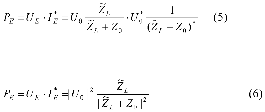
- Die Leistung am Last-Leitungswellenwiderstand, also in der Elektrodenspitze, kann aus der hin- und rücklaufenden Welle berechnet werden.

- Mit


- ab und erhält somit durch Einsetzen und Umstellen der Gleichungen (1.a) und (1.b)


- Es folgt anhand der
Figuren 4, 5 und6 eine Erläuterung zur Ermittlung der zugrunde zu legenden frequenzabhängigen Wellenleitungswiderstandswerte. -
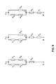
Figur4 und 5 zeigen in einem schematischen Ersatzschaltbild Ersatzwiderstände zwischen den Elektrodenpolen Spitze (Tip) 22 und Ring 24 einer Elektrodenleitung 22 und ihrer Gegenelektrode in einer Sternschaltung (Figur 4 ) und Dreieckschaltung (Figur 5 ). -
Figur6 zeigt diejenigen drei Konstellationen, in denen jeweils ein Gesamtwiderstand zwischen zwei Punkten A und B gemessen wird. Aus den Gesamtwiderständen dieser drei Netzwerke lassen sich für jede Frequenz, bei der gemessen wird, jeweils die Teilwiderstände RT, RR und RG errechnen. - Es wird ein Widerstand der Innenwendel Ri, der mit 37,6 Ω, und ein Widerstand der Außenwendel Ra, der mit 106,7 Ω bei jeder der verwendeten Frequenzen gemessen wurde, für die Berechnung der Widerstände der Elektrodenpole berücksichtigt werden. Der Leitungswiderstand der Gegenelektrode wird mit 0 Ω, veranschlagt. Ri und Ra sind getrennt gemessen und bekannt.
- Es wurden zwei verschiedene Elektrodenleitungen vermessen, die in ein Glas physiologischer Kochsalzlösung mit einer Gegenelektrode aus Platin-Iridium-Legierung gehalten wurden. Um zunächst die Induktivität, Kapazität und Widerstand der Zuleitungen zu isolieren, wurde bei verschiedenen Frequenzen mit einem LCR-Meter, Type: Fluke PM6306, die Impedanz zwischen Innen- und Außenleiter einer Elektrodenleitung mit der Spitze entweder in der Lösung oder freihängend in der Luft gemessen.
- Die von den Erfindern in einer Versuchsreihe erzielten Messergebnisse sind nachfolgend in Tabelle 1 dargestellt. In jeder Zelle der Tabelle sind zwei Werte untereinander aufgeführt, die an zwei unterschiedlichen Elektrodenleitungen (oberer Wert BIOTRONIK Setrox S60, unterer Wert BIOTRONIK Setrox S45) gemessen wurden.
Tabelle 1 Frequenz Tip gegen Ring mit Kopf in der Lösung Tip gegen Ring mit Kopf in der Luft R/Ω C/nF R/Ω C/nF 1MHz 275,7 64 58 75,3 222,2 Nicht messbar 34,9 59,8 500kHz 277,8 340 55,2 83,3 222,7 0,13 38,0 68,9 200kHz 278,4 514 57,06 83,23 223,8 412 38,15 67,7 100kHz 278,87 721,4 56,65 83,18 224,22 523 40,15 67,68 50kHz 279,74 1029 66,24 83,19 225,37 641 51,70 67,73 20kHz 281,3 1630 115,8 83,22 227,8 890 Nicht messbar 67,74 - Die Messwerte der Tabelle lassen erkennen, dass ab Frequenzen von 500kHz die Induktivität der Leitung bei Messung mit offenem Kopf schon eine Rolle spielt. Aus den Messungen mit Kopf in der Luft (Unterbrechung zwischen Innen- und Außenleiter, bzw. zwischen Tip und Ring) ließ sich ein Wert des Kapazitätsbelages zwischen Innen- und Außenwendel zu 140 bis 150pF/m bestimmen.
- Den Widerstandsbelag von Innen- und Außenwendel kann man mit Kopf im Wasser bei Frequenzen unter 500kHz bestimmen, wenn man den Widerstand zwischen Tip und Ring abzieht. Man sieht bei der Messung mit Kopf in der Salzlösung, dass bei höherer Frequenz die Induktivität der Leitung sich immer mehr auf das Messergebnis auswirkt und je nach Elektrodentyp, hier bei der Setrox S40, ab 1MHz Frequenz die Kapazität der Leitung sogar schon ausgleichen kann.
- Bei niedrigen Frequenzen um 20kHz zeigt sich als kapazitiver Widerstand die Faraday-Kapazität der beiden Elektroden in Tabelle stark unterschiedlich und viel zu gering. Das wird auf Schäden an der fraktalen Struktur von Tip und Ring durch Einspannen der Elektrodenspitzen bei vorangegangenen Messungen zurückgeführt. Die Messwerte ab 50kHz Frequenz werden davon aber fast nicht mehr beeinflusst.
- Es hat sich gezeigt, dass die gemessenen Widerstandswerte von der Position des Elektrodenkopfes zur Gegenelektrode unbeeinflusst bleiben, wenn die beiden weiter als ca. 4 Zentimeter voneinander entfernt sind. Das lässt schließen, dass die Widerstände RT, RR und RG aus
Figur 4 die Widerstände des jeweiligen Elektrodenpols gegen einen unendlich fernen Punkt mit Nullpotenzial sind. - Die Widerstände der Elektroden untereinander wurden bei der Elektrodenleitung BIOTRONIK Setrox S60 wie folgt gemessen
Tabelle 2 Frequenz Tip und Ring gegen Gegenelektrode Ring und Gegenelektr. Gegen Tip Tip und Gegenelektr. gegen Ring 1MHz 77,7Ω 137,6Ω 156Ω 1,64µH 70nF 3,26µH 500kHz 77,8Ω 137,8Ω 155,4Ω 2,5µH 0,22µH 3,98µH 200kHz 77,9Ω 138,04Ω Nicht gemessen 3,0µH 1,44µF 100kHz 78,2Ω 138,48Ω 154,77Ω Nicht messbar 1,222µF 3,41µH 50kHz 78,538Ω 139,22Ω 154,86Ω Nicht messbar 1,5µF 3,49µH 20kHz 79,026Ω 140Ω 155,20Ω 9,11µF 2,3µF 28,27µF - Es ergeben sich für die Widerstände von Tip, Ring und Gegenelektrode bei verschiedenen Frequenzen die in der nachfolgenden Tabelle 3 zusammengestellten Werte. Der Durchschnittswert (∅) ist fett gedruckt in der unteren Zeile eingetragen, dabei wurden für RT und RR der Mittelwert und für RG der Median veranschlagt.
Frequenz RT RR RG 1MHz 91,88Ω 41,15Ω 8,70Ω 500kHz 91,81Ω 40,28Ω 9,01Ω 100kHz 91,94Ω 39,11Ω 9,63Ω 50kHz 92,51Ω 39,02Ω 9,83Ω 20kHz 92,99Ω 39,06Ω 10,17Ω ∅ 92,2Ω 39,7Ω 9,6Ω - Die Leitfähigkeit des Elektrolyts ist auf σ=1,57 ... 1,67 S/m eingestellt und seine Permittivität ist ε=80·8,85·10-12 As/Vm so lässt sich mit der Formel

Tip Ring Gegenelektrode Kapazität C 4,54pF ... 4,95pF 10,4pF ... 11,7pF 37,4pF ... 54,2pF ∅ 4,74pF 11,0pF 45,5pF kapazitiver Blindwiderstand bei 64MHz (Larmor-Frequenz bei MRI in 1,5T-Geräten) XC 64MHz -j503Ω ... -j547Ω -j212Ω ... -j238Ω -j45Ω... -j65Ω ∅ -j524Ω -j226Ω -j55Ω Widerstand umgerechnet auf Kochsalzlösung nach ASTM (σ=0,474 S/m) R ∅ 315Ω 136Ω 33Ω Widerstand umgerechnet auf eine 0,03 molare Lösung (σ=0,310 ... 0,370 S/m) R ∅ 440Ω 190Ω 46Ω - Eine Kochsalzlösung mit σ=0,474 S/m liefert die richtigen Ergebnisse für die Messung der Erwärmung nach der ASTM Norm (American Standard for Testing and Material), während eine 0,03 molare Kochsalzlösung die richtigen Werte für den Widerstand von Tip und Ring für Sensing und Pacing im Gewebe liefert.
-
Figur7 ist eine schematische Darstellung eines Beispiels eines Funktionsleiters einer Elektrodenleitung. Das Ausführungsbeispiel lässt sich auch durch das Ersatzschaltbild derFigur 3 darstellen. Daher werden inFigur 7 weitgehend identische Bezugszeichen wie inFigur 3 verwendet. Der Funktionsleiter 26 hat einen hier nicht in voller Länge dargestellten ersten Längsabschnitt L1, in dem sein Innenleiter als Hohlwendel 26.1 ausgeführt ist und einen - Leitungswellenwiderstand Z0 bildet. Der Innenleiter 26.1 ist in diesem ersten Längsabschnitt L1 von einer Isolierung 26.3 umgeben, beispielsweise einer Silikonisolierung mit einer relativen Primitivität von εr = 3 sowie einer verschwindenden elektrische Leitfähigkeit σ =0S/m.
- Im zum ersten Längsabschnitt L1 vergleichsweise sehr kurzen zweiten Längsabschnitt L2 des Funktionsleiters 26 ist der Innenleiter als zylindrischer Leiter 26.2 von beispielsweise 2 Millimeter Durchmesser und 10 Millimeter Länge gebildet, der mit einer Isolationsschicht, einem inneren Dielektrikum (z.B. einer Lackschicht) einer Stärke d2 von 10 Mikrometer umgeben ist. Dieser zylindrische Leiter 26.2 weist einen Leitungswellenwiderstand für elektromagnetische Radiofrequenzwellen von Z1 =(13,16+j6,67)Ω auf.
- Zum Vergleich: Im ersten Längsabschnitt L1 hat die Hohlwendel 26.1 einen deutlich höheren Leitungswellenwiderstand für elektromagnetische Radiofrequenzwellen, wie sich aus den oben im Zusammenhang mit den
Figuren 4 bis 6 dargestellten Berechnungen und Messungen ergibt. Der entsprechende Leitungswellenwiderstand des Elektrodenpols 22 beträgt (bei εr = 80, σ = 0,47S / m für Körpergewebe), wie erwähnt beispielsweise ZL=233-j138Ω und liegt also ebenso deutlich über dem des Innenleiterstücks 26.2 im zweiten Längsabschnitt L2. -
Figur 8 zeigt eine graphische Darstellung des Ergebnisses einer Simulationsrechnung, welche die elektrische Feldstärke sowie magnetische Feldlinien bzw. Umrisslinien von magnetischen Flussröhren um einen Längsabschnitt von 0 bis 1 Meter eines langgestreckten elektrischen Leiters gemäß dem Stand der Technik wiedergibt, der dem Ersatzschaltbild derFigur 2 entspricht und einen inneren Elektrolytdurchmesser diel von 2mm hat.. - Die dünn gezeichneten Linien sind die Feldlinien bzw. Flussröhren. Sie zeigen den Verlauf des Feldes, das sich um die sich auf der Abszisse des Diagramms erstreckende zylindrische Leitung ausbildet, wenn sich eine Hochfrequenzwelle in der Zeichnungsebene von links nach rechts entlang der Leitung ausbreitet. Auf der Ordinate ist der Abstand von der Abszisse in Metern zwischen -0,25 und 0,25 Metern aufgetragen. Negative Abstandswerte sind als Abstand in entgegengesetzter Richtung zur Richtung positiver Abstandswerte zu verstehen. Die fett gezeichneten Linien sind Isolinien und kodieren die elektromagnetische Energie, die sich in den betreffenden Radiuselementen 2π ρdρ befindet.
- Die elektromagnetische Energie ist als über die Zeit gemittelte Energie zu verstehen, so dass sie nicht an den Stellen am größten ist, wo die Feldlinien dicht beieinander liegen, sondern generell dicht an der Leitung.
- Zwischen zwei Isolinien nimmt der Energiewert logarithmisch um Faktor zehn ab. Daraus, dass die Feldlinienknäule, nach rechts hin kleiner werden, bzw. die Isolinien nach rechts hin konisch zulaufen, erkennt man, dass das Feld nach rechts hin abnimmt, die Leitung also bedämpft ist.
- Die Figur zeigt das Feldbild um eine Elektrode nach dem Stand der Technik im Körpergewebe mit der Leitfähigkeit σ=4,74S/m und der relativen Permittivität εr =80, auf der sich eine Welle mit 64MHz ausbreitet. Der komplexwertige Wellenwiderstand ist in diesem Beispiel

- Die Elektrodenspitze ist durch einen komplexen Widerstand von ZL=233-j138Ω gegen das Körpergewebe darstellbar. Der Lastwiderstand unterscheidet sich in seiner Größe nicht allzu viel vom Innenwiderstand, so dass in diesem Beispiel 61% der maximal möglichen Wirkleistung umgesetzt wird.
- Die magnetischen Feldlinien kringeln sich zylinderrund um die Leitung herum und stehen an jeder Stelle genau senkrecht auf den elektrischen Feldlinien. Es handelt sich hier also um die Ausbreitung einer transversalen elektromagnetische (TEM-) Welle. Man erkennt, dass ein isolierter Draht wie eine Elektrodenleitung im Körpergewebe eine Leitung darstellt, auf der sich eine TEM-Welle ausbreiten kann. Diese Leitung hat einen Wellenwiderstand, eine Dämpfung und eine Wellenlänge, die von der Frequenz abhängig sind. Die Länge einer dieser Zwiebeln ist eine halbe Wellenlänge. Man kann aus dem Diagramm die zu erwartende Wellenlänge von 23cm herauslesen.
- Wenn nun jedoch ein Stück Leitung der Länge 1 mit einem von Z0 und ZL verschiedenen Leitungswellenwiderstand zwischengeschaltet wird, das den Lastwiderstand ZL auf den Wert

Figur9 erläutert. -
Figur 9 zeigt zum Vergleich eineFigur 8 entsprechende graphische Darstellung des Ergebnisses einer weiteren Simulationsrechnung, welche die elektrische Feldstärke sowie magnetische Feldlinien bzw. Umrisslinien von magnetischen Flussröhren um einen Längsabschnitt von 0 bis 1 Meter eines langgestreckten elektrischen Leiters gemäß dem Ausführungsbeispiel derFigur 7 wiedergibt. Wie die Abbildung unten zeigt, weist eine solche Elektrodenleitung bei der Frequenz 64MHz auch eine starke Dämpfung auf. Die Energie am rechten Teil des Diagramms, also in Richtung zum distalen Ende der Leitung hin, ist deutlich geringer als bei der Elektrodenleitung nach dem Stand der Technik, deren Werte inFigur8 dargestellt sind. - Zur weiteren Veranschaulichung der Transformationseigenschaften der Leistung ist in den Diagrammen der
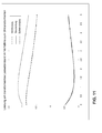
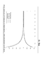
Figuren 10 bis 12 zunächst die Leistung an der Elektrodenspitze für ein Ausführungsbeispiel aufgezeichnet, bei dem zwischen einem Elektrodenpol in Form einer Elektrodenspitze und der Funktionsleitung ein kurzes, schwach bedämpftes Stück Leitung eingebaut ist. Auf der Abszisse der Diagramme derFiguren 10 bis 12 ist eine ein Längenparameter in Meter abgetragen, und an der Ordinate der Wert eines jeweiligen Leistungsparameters, wenn ein Stück Leitung mit einer an der Abszisse jeweils angegebenen Länge 1 zwischengesetzt ist, im Verhältnis zum betreffenden Leistungsparameter ohne Zwischenstück (1=0). -
Figur 10 zeigt, dass über die Länge der Leitung periodische Schwankungen der Verhältnisse der Leistungsparameter Scheinleistung, Blindleistung und Wirkleistung auftreten. Über die Länge von 0 Zentimeter (proximales Ende) bis 20 Zentimeter ist über 7 Perioden eine Dämpfung erkennbar. - Im Diagramm der
Figur 11 ist die Länge des eingefügten Leitungsstück auf der Abszisse abgetragen und das jeweilige Leistungsverhältnis am Lastwiderstand der Elektrodenspitze auf der Ordinate. Man erkennt an den zunächst über eine Länge von knapp 2 Millimetern ansteigenden Kurven der Wirkleistung und der Scheinleitung, dass das kurze Leitungsstück zur Reduzierung der Leistungsparameter länger als 2 Millimeter sein soll. Denn bis zu einer Länge von ca. 0,5 Millimeter steigt das Verhältnis der Wirkleistung mit dem zusätzlichen Leitungsstück zur Wirkleistung ohne das zusätzliche Leitungsstück an der Elektrodenspitze wegen der Transformationseigenschaften sogar. Bei einem 1cm langen Leitungsstück ist die Leistung in der Elektrodenspitze schon auf etwa die Hälfte reduziert. - Günstiger sehen die Verhältnisse sogar noch aus, wenn man die Dämpfung der Leitung voll berücksichtigt, wie das Diagramm der
Figur 12 zeigt. Bei voller Berücksichtigung der Dämpfung sinkt die Leistung am Lastwiderstand (Elektrodenspitze) schon nach 1 Millimeter Leitung auf unter die Hälfte des Wertes am Anfang der Leitung.
Claims (11)
- Temporär oder permanent implantierbares medizinisches Gerät (10) mit mindestens einem langgestreckten elektrischen Leiter (26), der durch ein Dielektrikum mit dem inneren Durchmesser diel von umliegenden Material isoliert ist,- der einen Elektrodenpol (22, 24) zur Abgabe von Therapiesignalen oder zur Erfassung von Diagnosesignalen aufweist, welcher im implantierten Zustand einen Lastwiderstand ZL für elektromagnetische Wellen darstellt,- der zwischen seinem proximalen Ende und dem Elektrodenpol (22, 24) mindestens einen ersten Längsabschnitt (L1) eines ersten Leitungs-Wellenwiderstandes Z0 für elektromagnetische Wellen aufweist, und- der unmittelbar angrenzend an den ersten Längsabschnitt (L1) mindestens einen zweiten (L2), mindestens 0,25 innere Durchmesser (diel) langen, im Vergleich mit dem ersten Längsabschnitt kürzeren Längsabschnitt eines zweiten Leitungswellenwiderstandes Z1 für elektromagnetische Wellen aufweist, wobei der zweite Leitungswellenwiderstand größer oder kleiner als der erste Leitungswellenwiderstand und größer oder kleiner ist und als der Lastwiderstand ist.
- Medizinisches Gerät nach einem der vorstehenden Ansprüche, bei dem ein Realteil des zweiten Leitungswellenwiderstands für elektromagnetische Radiofrequenz-Wellen um einen Faktor von mindestens 2 kleiner ist als ein Realteil des ersten Leitungswellenwiderstands.
- Medizinisches Gerät nach einem der vorstehenden Ansprüche, bei dem im Funktionsleiter (26, 26') in Richtung zum distalen Ende hin an den zweiten Längsabschnitt (L2) ein weiterer erster Längsabschnitt (L1) des ersten Leitungswellenwiderstands Z0 anschließt.
- Medizinisches Gerät nach einem der vorstehenden Ansprüche, bei dem der zweite Längsabschnitt (L2) länger als 2 Millimeter ist.
- Medizinisches Gerät nach einem der vorstehenden Ansprüche, bei dem der zweite Längsabschnitt (L2) kürzer als 20 Millimeter ist.
- Medizinisches Gerät nach einem der vorstehenden Ansprüche, bei dem der zweite Längsabschnitt (L2) maximal 10 Millimeter lang ist.
- Medizinisches Gerät nach einem der vorstehenden Ansprüche, bei dem der Funktionsleiter (26) einen Innenleiter und einen hohlzylindrischen Außenleiter aufweist, wobei der Innenleiter im zweiten Längsabschnitt (L2) eine vom Innenleiter im ersten Längsabschnitt (L1) abweichende geometrische Form hat.
- Medizinisches Gerät nach einem der vorstehenden Ansprüche, bei dem der Innenleiter im ersten Längsabschnitt (L1) des elektrischen Leiters (20) hohlwendelförmig und im zweiten Längsabschnitt (L2) zylinderförmig ist.
- Medizinisches Gerät nach Anspruch 8, bei dem der zylinderförmige Innenleiter im zweiten Längsabschnitt (L2) vom Außenleiter durch ein Dielektrikum von mindestens 5 Mikrometer Dicke isoliert ist.
- Medizinisches Gerät nach einem der vorstehenden Ansprüche, bei dem der Elektrodenpol eine Elektrodenspitze (22) am distalen Ende des elektrischen Leiters (20) aufweist.
- Medizinisches Gerät nach Anspruch 9, bei dem die Elektrodenspitze (22) unmittelbar an den zweiten Längsabschnitt (L2) anschließt.
Applications Claiming Priority (1)
| Application Number | Priority Date | Filing Date | Title |
|---|---|---|---|
| US201061424075P | 2010-12-17 | 2010-12-17 |
Publications (3)
| Publication Number | Publication Date |
|---|---|
| EP2465571A2 true EP2465571A2 (de) | 2012-06-20 |
| EP2465571A3 EP2465571A3 (de) | 2012-07-04 |
| EP2465571B1 EP2465571B1 (de) | 2017-01-18 |
Family
ID=45217372
Family Applications (1)
| Application Number | Title | Priority Date | Filing Date |
|---|---|---|---|
| EP11191741.5A Not-in-force EP2465571B1 (de) | 2010-12-17 | 2011-12-02 | Implantierbares Gerät |
Country Status (2)
| Country | Link |
|---|---|
| US (1) | US8942826B2 (de) |
| EP (1) | EP2465571B1 (de) |
Family Cites Families (5)
| Publication number | Priority date | Publication date | Assignee | Title |
|---|---|---|---|---|
| ATE484757T1 (de) * | 2000-02-01 | 2010-10-15 | Surgivision Inc | Transseptale nadelantenne für ein mr- bildgebungsgerät |
| US8055351B2 (en) * | 2005-10-21 | 2011-11-08 | Boston Scientific Neuromodulation Corporation | MRI-safe high impedance lead systems |
| US8386057B2 (en) | 2006-11-17 | 2013-02-26 | Biotronik Crm Patent Ag | Electrode catheter for interventional use |
| US8275464B2 (en) | 2007-12-06 | 2012-09-25 | Cardiac Pacemakers, Inc. | Leads with high surface resistance |
| EP2349457B1 (de) | 2008-10-15 | 2014-06-25 | Sapiens Steering Brain Stimulation B.V. | Sonde für eine implantierbare medizinische vorrichtung |
-
2011
- 2011-11-21 US US13/301,675 patent/US8942826B2/en not_active Expired - Fee Related
- 2011-12-02 EP EP11191741.5A patent/EP2465571B1/de not_active Not-in-force
Non-Patent Citations (1)
| Title |
|---|
| None |
Also Published As
| Publication number | Publication date |
|---|---|
| US20120157812A1 (en) | 2012-06-21 |
| EP2465571A3 (de) | 2012-07-04 |
| EP2465571B1 (de) | 2017-01-18 |
| US8942826B2 (en) | 2015-01-27 |
Similar Documents
| Publication | Publication Date | Title |
|---|---|---|
| EP1923094B1 (de) | Elektrodenkatheter zu Interventionszwecken | |
| EP1923095B1 (de) | Elektrode zu Interventionszwecken | |
| US8712544B2 (en) | Electromagnetic shield for a passive electronic component in an active medical device implantable lead | |
| EP2359898A2 (de) | Implantierbares Element mit Mitteln zur Verringerung einer Flussdichte | |
| US20140296952A1 (en) | Electromagnetic shield for a passive electronic component in an active medical device implantable lead | |
| EP2465572B1 (de) | MRT-kompatible implantierbare Leitung | |
| DE102020100121A1 (de) | Implantierbare Elektrode mit einer Stichleitung | |
| EP2110154B1 (de) | Vorrichtung zur Reduktion der Störungsanfälligkeit für langgestreckte Implantate | |
| EP2578268B1 (de) | Temperatursensor für ein implantierbares medizinisches Gerät | |
| EP2446922B1 (de) | Implantierbare Leiter mit zusätzlichen Leitern zur Feldentkopplung | |
| EP2465569B1 (de) | Implantierbares Gerät | |
| EP2985053A1 (de) | Implantierbare elektrische leitung | |
| EP2468353B1 (de) | Implantierbares Gerät | |
| EP2110156B1 (de) | Feldentkopplungs-Element zur Verwendung mit einer implantierbaren Leitung und implantierbares medizinisches Gerät | |
| EP2465571B1 (de) | Implantierbares Gerät | |
| EP2848282B1 (de) | Implantierbares Gerät | |
| EP2478933A2 (de) | Implantierbares Gerät | |
| EP2465573B1 (de) | Implantierbares Gerät | |
| EP2985054B1 (de) | Implantierbares gerät mit elektrischem filter | |
| EP3025756B1 (de) | Im aktiven implantat integrierte elektrodenverlängerung | |
| EP2465570B1 (de) | Implantierbares Gerät | |
| EP2505229A2 (de) | Implantierbares Gerät | |
| EP2468356B1 (de) | Implantierbares Gerät | |
| DE102007022333A1 (de) | Elektrode zu Interventionszwecken | |
| EP2457613A1 (de) | Implantierbare Leitung mit einem langgestreckten Leitungskörper |
Legal Events
| Date | Code | Title | Description |
|---|---|---|---|
| PUAL | Search report despatched |
Free format text: ORIGINAL CODE: 0009013 |
|
| PUAI | Public reference made under article 153(3) epc to a published international application that has entered the european phase |
Free format text: ORIGINAL CODE: 0009012 |
|
| AK | Designated contracting states |
Kind code of ref document: A2 Designated state(s): AL AT BE BG CH CY CZ DE DK EE ES FI FR GB GR HR HU IE IS IT LI LT LU LV MC MK MT NL NO PL PT RO RS SE SI SK SM TR |
|
| AX | Request for extension of the european patent |
Extension state: BA ME |
|
| AK | Designated contracting states |
Kind code of ref document: A3 Designated state(s): AL AT BE BG CH CY CZ DE DK EE ES FI FR GB GR HR HU IE IS IT LI LT LU LV MC MK MT NL NO PL PT RO RS SE SI SK SM TR |
|
| AX | Request for extension of the european patent |
Extension state: BA ME |
|
| RIC1 | Information provided on ipc code assigned before grant |
Ipc: A61N 1/05 20060101AFI20120529BHEP |
|
| 17P | Request for examination filed |
Effective date: 20121212 |
|
| RIC1 | Information provided on ipc code assigned before grant |
Ipc: A61N 1/08 20060101ALN20131217BHEP Ipc: A61N 1/05 20060101AFI20131217BHEP |
|
| 17Q | First examination report despatched |
Effective date: 20140218 |
|
| RIC1 | Information provided on ipc code assigned before grant |
Ipc: A61N 1/08 20060101ALN20160331BHEP Ipc: A61N 1/05 20060101AFI20160331BHEP |
|
| RIC1 | Information provided on ipc code assigned before grant |
Ipc: A61N 1/08 20060101ALN20160428BHEP Ipc: A61N 1/05 20060101AFI20160428BHEP |
|
| RIC1 | Information provided on ipc code assigned before grant |
Ipc: A61N 1/08 20060101ALN20160512BHEP Ipc: A61N 1/05 20060101AFI20160512BHEP |
|
| GRAP | Despatch of communication of intention to grant a patent |
Free format text: ORIGINAL CODE: EPIDOSNIGR1 |
|
| INTG | Intention to grant announced |
Effective date: 20160617 |
|
| GRAS | Grant fee paid |
Free format text: ORIGINAL CODE: EPIDOSNIGR3 |
|
| GRAJ | Information related to disapproval of communication of intention to grant by the applicant or resumption of examination proceedings by the epo deleted |
Free format text: ORIGINAL CODE: EPIDOSDIGR1 |
|
| GRAL | Information related to payment of fee for publishing/printing deleted |
Free format text: ORIGINAL CODE: EPIDOSDIGR3 |
|
| GRAR | Information related to intention to grant a patent recorded |
Free format text: ORIGINAL CODE: EPIDOSNIGR71 |
|
| INTC | Intention to grant announced (deleted) | ||
| RIC1 | Information provided on ipc code assigned before grant |
Ipc: A61N 1/05 20060101AFI20161021BHEP Ipc: A61N 1/08 20060101ALN20161021BHEP |
|
| GRAA | (expected) grant |
Free format text: ORIGINAL CODE: 0009210 |
|
| INTG | Intention to grant announced |
Effective date: 20161116 |
|
| AK | Designated contracting states |
Kind code of ref document: B1 Designated state(s): AL AT BE BG CH CY CZ DE DK EE ES FI FR GB GR HR HU IE IS IT LI LT LU LV MC MK MT NL NO PL PT RO RS SE SI SK SM TR |
|
| REG | Reference to a national code |
Ref country code: GB Ref legal event code: FG4D Free format text: NOT ENGLISH |
|
| REG | Reference to a national code |
Ref country code: CH Ref legal event code: EP |
|
| REG | Reference to a national code |
Ref country code: AT Ref legal event code: REF Ref document number: 862547 Country of ref document: AT Kind code of ref document: T Effective date: 20170215 |
|
| REG | Reference to a national code |
Ref country code: IE Ref legal event code: FG4D Free format text: LANGUAGE OF EP DOCUMENT: GERMAN |
|
| REG | Reference to a national code |
Ref country code: DE Ref legal event code: R096 Ref document number: 502011011541 Country of ref document: DE |
|
| REG | Reference to a national code |
Ref country code: NL Ref legal event code: MP Effective date: 20170118 |
|
| REG | Reference to a national code |
Ref country code: LT Ref legal event code: MG4D |
|
| PG25 | Lapsed in a contracting state [announced via postgrant information from national office to epo] |
Ref country code: NL Free format text: LAPSE BECAUSE OF FAILURE TO SUBMIT A TRANSLATION OF THE DESCRIPTION OR TO PAY THE FEE WITHIN THE PRESCRIBED TIME-LIMIT Effective date: 20170118 |
|
| PG25 | Lapsed in a contracting state [announced via postgrant information from national office to epo] |
Ref country code: NO Free format text: LAPSE BECAUSE OF FAILURE TO SUBMIT A TRANSLATION OF THE DESCRIPTION OR TO PAY THE FEE WITHIN THE PRESCRIBED TIME-LIMIT Effective date: 20170418 Ref country code: FI Free format text: LAPSE BECAUSE OF FAILURE TO SUBMIT A TRANSLATION OF THE DESCRIPTION OR TO PAY THE FEE WITHIN THE PRESCRIBED TIME-LIMIT Effective date: 20170118 Ref country code: LT Free format text: LAPSE BECAUSE OF FAILURE TO SUBMIT A TRANSLATION OF THE DESCRIPTION OR TO PAY THE FEE WITHIN THE PRESCRIBED TIME-LIMIT Effective date: 20170118 Ref country code: HR Free format text: LAPSE BECAUSE OF FAILURE TO SUBMIT A TRANSLATION OF THE DESCRIPTION OR TO PAY THE FEE WITHIN THE PRESCRIBED TIME-LIMIT Effective date: 20170118 Ref country code: GR Free format text: LAPSE BECAUSE OF FAILURE TO SUBMIT A TRANSLATION OF THE DESCRIPTION OR TO PAY THE FEE WITHIN THE PRESCRIBED TIME-LIMIT Effective date: 20170419 Ref country code: IS Free format text: LAPSE BECAUSE OF FAILURE TO SUBMIT A TRANSLATION OF THE DESCRIPTION OR TO PAY THE FEE WITHIN THE PRESCRIBED TIME-LIMIT Effective date: 20170518 |
|
| PG25 | Lapsed in a contracting state [announced via postgrant information from national office to epo] |
Ref country code: PL Free format text: LAPSE BECAUSE OF FAILURE TO SUBMIT A TRANSLATION OF THE DESCRIPTION OR TO PAY THE FEE WITHIN THE PRESCRIBED TIME-LIMIT Effective date: 20170118 Ref country code: SE Free format text: LAPSE BECAUSE OF FAILURE TO SUBMIT A TRANSLATION OF THE DESCRIPTION OR TO PAY THE FEE WITHIN THE PRESCRIBED TIME-LIMIT Effective date: 20170118 Ref country code: ES Free format text: LAPSE BECAUSE OF FAILURE TO SUBMIT A TRANSLATION OF THE DESCRIPTION OR TO PAY THE FEE WITHIN THE PRESCRIBED TIME-LIMIT Effective date: 20170118 Ref country code: PT Free format text: LAPSE BECAUSE OF FAILURE TO SUBMIT A TRANSLATION OF THE DESCRIPTION OR TO PAY THE FEE WITHIN THE PRESCRIBED TIME-LIMIT Effective date: 20170518 Ref country code: RS Free format text: LAPSE BECAUSE OF FAILURE TO SUBMIT A TRANSLATION OF THE DESCRIPTION OR TO PAY THE FEE WITHIN THE PRESCRIBED TIME-LIMIT Effective date: 20170118 Ref country code: BG Free format text: LAPSE BECAUSE OF FAILURE TO SUBMIT A TRANSLATION OF THE DESCRIPTION OR TO PAY THE FEE WITHIN THE PRESCRIBED TIME-LIMIT Effective date: 20170418 Ref country code: LV Free format text: LAPSE BECAUSE OF FAILURE TO SUBMIT A TRANSLATION OF THE DESCRIPTION OR TO PAY THE FEE WITHIN THE PRESCRIBED TIME-LIMIT Effective date: 20170118 |
|
| REG | Reference to a national code |
Ref country code: DE Ref legal event code: R097 Ref document number: 502011011541 Country of ref document: DE |
|
| PG25 | Lapsed in a contracting state [announced via postgrant information from national office to epo] |
Ref country code: EE Free format text: LAPSE BECAUSE OF FAILURE TO SUBMIT A TRANSLATION OF THE DESCRIPTION OR TO PAY THE FEE WITHIN THE PRESCRIBED TIME-LIMIT Effective date: 20170118 Ref country code: CZ Free format text: LAPSE BECAUSE OF FAILURE TO SUBMIT A TRANSLATION OF THE DESCRIPTION OR TO PAY THE FEE WITHIN THE PRESCRIBED TIME-LIMIT Effective date: 20170118 Ref country code: SK Free format text: LAPSE BECAUSE OF FAILURE TO SUBMIT A TRANSLATION OF THE DESCRIPTION OR TO PAY THE FEE WITHIN THE PRESCRIBED TIME-LIMIT Effective date: 20170118 Ref country code: IT Free format text: LAPSE BECAUSE OF FAILURE TO SUBMIT A TRANSLATION OF THE DESCRIPTION OR TO PAY THE FEE WITHIN THE PRESCRIBED TIME-LIMIT Effective date: 20170118 Ref country code: RO Free format text: LAPSE BECAUSE OF FAILURE TO SUBMIT A TRANSLATION OF THE DESCRIPTION OR TO PAY THE FEE WITHIN THE PRESCRIBED TIME-LIMIT Effective date: 20170118 |
|
| PLBE | No opposition filed within time limit |
Free format text: ORIGINAL CODE: 0009261 |
|
| STAA | Information on the status of an ep patent application or granted ep patent |
Free format text: STATUS: NO OPPOSITION FILED WITHIN TIME LIMIT |
|
| PG25 | Lapsed in a contracting state [announced via postgrant information from national office to epo] |
Ref country code: SM Free format text: LAPSE BECAUSE OF FAILURE TO SUBMIT A TRANSLATION OF THE DESCRIPTION OR TO PAY THE FEE WITHIN THE PRESCRIBED TIME-LIMIT Effective date: 20170118 Ref country code: DK Free format text: LAPSE BECAUSE OF FAILURE TO SUBMIT A TRANSLATION OF THE DESCRIPTION OR TO PAY THE FEE WITHIN THE PRESCRIBED TIME-LIMIT Effective date: 20170118 |
|
| 26N | No opposition filed |
Effective date: 20171019 |
|
| PG25 | Lapsed in a contracting state [announced via postgrant information from national office to epo] |
Ref country code: SI Free format text: LAPSE BECAUSE OF FAILURE TO SUBMIT A TRANSLATION OF THE DESCRIPTION OR TO PAY THE FEE WITHIN THE PRESCRIBED TIME-LIMIT Effective date: 20170118 |
|
| GBPC | Gb: european patent ceased through non-payment of renewal fee |
Effective date: 20171202 |
|
| PG25 | Lapsed in a contracting state [announced via postgrant information from national office to epo] |
Ref country code: MT Free format text: LAPSE BECAUSE OF FAILURE TO SUBMIT A TRANSLATION OF THE DESCRIPTION OR TO PAY THE FEE WITHIN THE PRESCRIBED TIME-LIMIT Effective date: 20170118 Ref country code: LU Free format text: LAPSE BECAUSE OF NON-PAYMENT OF DUE FEES Effective date: 20171202 |
|
| REG | Reference to a national code |
Ref country code: FR Ref legal event code: ST Effective date: 20180831 |
|
| REG | Reference to a national code |
Ref country code: BE Ref legal event code: MM Effective date: 20171231 |
|
| PG25 | Lapsed in a contracting state [announced via postgrant information from national office to epo] |
Ref country code: FR Free format text: LAPSE BECAUSE OF NON-PAYMENT OF DUE FEES Effective date: 20180102 |
|
| PG25 | Lapsed in a contracting state [announced via postgrant information from national office to epo] |
Ref country code: GB Free format text: LAPSE BECAUSE OF NON-PAYMENT OF DUE FEES Effective date: 20171202 Ref country code: BE Free format text: LAPSE BECAUSE OF NON-PAYMENT OF DUE FEES Effective date: 20171231 |
|
| REG | Reference to a national code |
Ref country code: AT Ref legal event code: MM01 Ref document number: 862547 Country of ref document: AT Kind code of ref document: T Effective date: 20171202 |
|
| PG25 | Lapsed in a contracting state [announced via postgrant information from national office to epo] |
Ref country code: AT Free format text: LAPSE BECAUSE OF NON-PAYMENT OF DUE FEES Effective date: 20171202 |
|
| PG25 | Lapsed in a contracting state [announced via postgrant information from national office to epo] |
Ref country code: HU Free format text: LAPSE BECAUSE OF FAILURE TO SUBMIT A TRANSLATION OF THE DESCRIPTION OR TO PAY THE FEE WITHIN THE PRESCRIBED TIME-LIMIT; INVALID AB INITIO Effective date: 20111202 Ref country code: MC Free format text: LAPSE BECAUSE OF FAILURE TO SUBMIT A TRANSLATION OF THE DESCRIPTION OR TO PAY THE FEE WITHIN THE PRESCRIBED TIME-LIMIT Effective date: 20170118 |
|
| PG25 | Lapsed in a contracting state [announced via postgrant information from national office to epo] |
Ref country code: CY Free format text: LAPSE BECAUSE OF NON-PAYMENT OF DUE FEES Effective date: 20170118 |
|
| PG25 | Lapsed in a contracting state [announced via postgrant information from national office to epo] |
Ref country code: MK Free format text: LAPSE BECAUSE OF FAILURE TO SUBMIT A TRANSLATION OF THE DESCRIPTION OR TO PAY THE FEE WITHIN THE PRESCRIBED TIME-LIMIT Effective date: 20170118 |
|
| PG25 | Lapsed in a contracting state [announced via postgrant information from national office to epo] |
Ref country code: TR Free format text: LAPSE BECAUSE OF FAILURE TO SUBMIT A TRANSLATION OF THE DESCRIPTION OR TO PAY THE FEE WITHIN THE PRESCRIBED TIME-LIMIT Effective date: 20170118 |
|
| PG25 | Lapsed in a contracting state [announced via postgrant information from national office to epo] |
Ref country code: AL Free format text: LAPSE BECAUSE OF FAILURE TO SUBMIT A TRANSLATION OF THE DESCRIPTION OR TO PAY THE FEE WITHIN THE PRESCRIBED TIME-LIMIT Effective date: 20170118 |
|
| PGFP | Annual fee paid to national office [announced via postgrant information from national office to epo] |
Ref country code: IE Payment date: 20211220 Year of fee payment: 11 |
|
| PGFP | Annual fee paid to national office [announced via postgrant information from national office to epo] |
Ref country code: CH Payment date: 20211222 Year of fee payment: 11 |
|
| PGFP | Annual fee paid to national office [announced via postgrant information from national office to epo] |
Ref country code: DE Payment date: 20211222 Year of fee payment: 11 |
|
| REG | Reference to a national code |
Ref country code: DE Ref legal event code: R119 Ref document number: 502011011541 Country of ref document: DE |
|
| REG | Reference to a national code |
Ref country code: CH Ref legal event code: PL |
|
| PG25 | Lapsed in a contracting state [announced via postgrant information from national office to epo] |
Ref country code: LI Free format text: LAPSE BECAUSE OF NON-PAYMENT OF DUE FEES Effective date: 20221231 Ref country code: IE Free format text: LAPSE BECAUSE OF NON-PAYMENT OF DUE FEES Effective date: 20221202 Ref country code: DE Free format text: LAPSE BECAUSE OF NON-PAYMENT OF DUE FEES Effective date: 20230701 Ref country code: CH Free format text: LAPSE BECAUSE OF NON-PAYMENT OF DUE FEES Effective date: 20221231 |