EP2465610A1 - Dispositif et procédé pour désintégrer des déchets liquides - Google Patents
Dispositif et procédé pour désintégrer des déchets liquides Download PDFInfo
- Publication number
- EP2465610A1 EP2465610A1 EP10461535A EP10461535A EP2465610A1 EP 2465610 A1 EP2465610 A1 EP 2465610A1 EP 10461535 A EP10461535 A EP 10461535A EP 10461535 A EP10461535 A EP 10461535A EP 2465610 A1 EP2465610 A1 EP 2465610A1
- Authority
- EP
- European Patent Office
- Prior art keywords
- liquid
- conduit
- liquid waste
- waste
- inlet
- Prior art date
- Legal status (The legal status is an assumption and is not a legal conclusion. Google has not performed a legal analysis and makes no representation as to the accuracy of the status listed.)
- Granted
Links
- 239000010808 liquid waste Substances 0.000 title claims abstract description 77
- 238000000034 method Methods 0.000 title claims description 18
- 239000002699 waste material Substances 0.000 claims abstract description 33
- 239000007788 liquid Substances 0.000 claims abstract description 25
- 238000007789 sealing Methods 0.000 claims abstract description 6
- 230000002596 correlated effect Effects 0.000 claims abstract description 4
- 238000004062 sedimentation Methods 0.000 claims description 15
- 238000009434 installation Methods 0.000 claims description 7
- 230000029087 digestion Effects 0.000 claims description 4
- OKTJSMMVPCPJKN-UHFFFAOYSA-N Carbon Chemical group [C] OKTJSMMVPCPJKN-UHFFFAOYSA-N 0.000 claims description 3
- 239000002245 particle Substances 0.000 description 5
- 239000010802 sludge Substances 0.000 description 4
- XLYOFNOQVPJJNP-UHFFFAOYSA-N water Substances O XLYOFNOQVPJJNP-UHFFFAOYSA-N 0.000 description 4
- 238000006243 chemical reaction Methods 0.000 description 3
- 244000005700 microbiome Species 0.000 description 2
- 239000000203 mixture Substances 0.000 description 2
- 239000010865 sewage Substances 0.000 description 2
- 239000002351 wastewater Substances 0.000 description 2
- 229910001347 Stellite Inorganic materials 0.000 description 1
- 239000003054 catalyst Substances 0.000 description 1
- AHICWQREWHDHHF-UHFFFAOYSA-N chromium;cobalt;iron;manganese;methane;molybdenum;nickel;silicon;tungsten Chemical compound C.[Si].[Cr].[Mn].[Fe].[Co].[Ni].[Mo].[W] AHICWQREWHDHHF-UHFFFAOYSA-N 0.000 description 1
- 238000005352 clarification Methods 0.000 description 1
- 238000005260 corrosion Methods 0.000 description 1
- 230000007797 corrosion Effects 0.000 description 1
- 230000000593 degrading effect Effects 0.000 description 1
- 230000000694 effects Effects 0.000 description 1
- 230000009969 flowable effect Effects 0.000 description 1
- 239000012530 fluid Substances 0.000 description 1
- 238000004519 manufacturing process Methods 0.000 description 1
- 239000000463 material Substances 0.000 description 1
- 238000012544 monitoring process Methods 0.000 description 1
- 239000003921 oil Substances 0.000 description 1
- 238000005086 pumping Methods 0.000 description 1
- 239000011541 reaction mixture Substances 0.000 description 1
- 238000012216 screening Methods 0.000 description 1
- 238000010008 shearing Methods 0.000 description 1
- 239000007787 solid Substances 0.000 description 1
- 239000002910 solid waste Substances 0.000 description 1
- 239000000126 substance Substances 0.000 description 1
Images

Classifications
-
- B—PERFORMING OPERATIONS; TRANSPORTING
- B02—CRUSHING, PULVERISING, OR DISINTEGRATING; PREPARATORY TREATMENT OF GRAIN FOR MILLING
- B02C—CRUSHING, PULVERISING, OR DISINTEGRATING IN GENERAL; MILLING GRAIN
- B02C18/00—Disintegrating by knives or other cutting or tearing members which chop material into fragments
- B02C18/0084—Disintegrating by knives or other cutting or tearing members which chop material into fragments specially adapted for disintegrating garbage, waste or sewage
- B02C18/0092—Disintegrating by knives or other cutting or tearing members which chop material into fragments specially adapted for disintegrating garbage, waste or sewage for waste water or for garbage
-
- B—PERFORMING OPERATIONS; TRANSPORTING
- B02—CRUSHING, PULVERISING, OR DISINTEGRATING; PREPARATORY TREATMENT OF GRAIN FOR MILLING
- B02C—CRUSHING, PULVERISING, OR DISINTEGRATING IN GENERAL; MILLING GRAIN
- B02C7/00—Crushing or disintegrating by disc mills
- B02C7/02—Crushing or disintegrating by disc mills with coaxial discs
- B02C7/06—Crushing or disintegrating by disc mills with coaxial discs with horizontal axis
Definitions
- the present invention relates to disintegration of liquid waste.
- a typical municipal sewage treatment plant comprises a screening stage in which large objects are separated from the sewage and a plurality of primary and secondary treatment stages, in which liquid waste is processed to remove suspended solids, oils, degrade the biological content etc.
- the efficiency of the secondary treatment stage of degrading the biological content of the sludge depends on the composition and structural properties of the sludge. It is therefore advantageous to pre-process the sludge entering the secondary treatment stages.
- a PCT application W02005/030659 discloses a device for treatment of a medium containing thread- and flake-forming microorganisms, such as effluent clarifier sludge, by means of a shear field for treating the microorganisms in the medium with mechanical stress, wherein the shear field is defined by a pair of planar elements separated from each other by a shear gap and rotatable around a vertical axis.
- the medium inlet is or may be connected to a feed pump such that the device does not siphon with at least a reduction, or an avoidance of cavitation in the shear gap.
- a US patent 3996012 discloses an apparatus for continuous treatment of substances in flowable form in conjunction with a catalyst for carrying out chemical reactions, the apparatus including a conical-shaped rotor and stator in opposed relationship defining between opposing working surfaces a reaction area and rotatable around a horizontal axis.
- the rotating rotor causes a turbulence effect in the reaction mixture which occurs in shearing at impact zones promoted by cavitation-like impact phenomena which intensify the chemical reaction.
- a European patent application EP1985357 discloses an apparatus for processing liquid fluids, such as wastewater, with use of cavitation process, wherein the liquid to be cavited is input between two planar elements rotatable with respect to each other around a horizontal axis and comprising alternate protrusion and channels.
- the known devices even if described as applicable for processing wastewater, require a clarified input medium, in order to avoid clogging of the rotatable elements.
- Such clarification may be typically performed by a filter installed at a pumping arrangement via which the medium to be processed is input to the device.
- the aim of the present invention is to provide a method and a device for disintegrating liquid waste which is convenient to operate and resilient to clogging.
- the object of the invention is a device for disintegrating liquid waste, comprising a waste processing chamber defined by a housing with a set of discs rotatable with respect to each other and comprising correlated concentric protrusions and channels defining a shear gap and configured to disintegrate liquid waste by cavitation during rotation, an inlet conduit connected to an inlet port for providing the liquid waste to an inlet chamber at the central portion of the waste processing chamber, an outlet conduit connected to an outer port for collecting the disintegrated liquid waste from a collecting chamber at the periphery of the waste processing chamber, wherein the waste processing chamber is liquid-tight and comprises liquid-tight sealing and an air vent mounted in the uppermost portion of the waste processing chamber, and the inlet conduit comprises switchable inlet valve means for providing to the inlet conduit a liquid waste of a first density from a liquid waste input conduit and a liquid of a second density lower than the first density from a supplementary conduit.
- At least one of the discs can be mounted on a rotatable horizontal shaft.
- the shaft can be rotatable by an engine with a speed from 2960 rpm to 3500 rpm.
- the device may further comprise a sensor configured to monitor at least one process parameter of the device and a controller configured to control the inlet valve means depending on the monitored process parameter.
- the sensor can be configured to monitor the temperature of the waste processing chamber.
- the sensor can be configured to monitor the temperature and/or load of an engine driving a rotatable disc.
- the sensor can be configured to monitor the density of the liquid in the outlet conduit.
- the liquid-tight sealing of the waste processing chamber may comprise carbon rings.
- the width of the shear gap can be from 0,4 mm to 0,6 mm.
- the object of the invention is also a liquid waste processing installation, comprising a sedimentation tank, the device for disintegrating liquid waste according to the invention, wherein the liquid waste inlet conduit is configured to collect liquid waste from the bottom portion of the sedimentation tank and wherein the outlet conduit is configured to output the disintegrated liquid waste to the upper portion of the sedimentation tank.
- the installation may further comprise an anaerobic digestion chamber, to which the liquid waste from the sedimentation tank is input, configured to produce biogas to be stored in a biogas tank, a biogas sensor configured to measure the amount of produced biogas, wherein the controller is further configured to control the working cycle of the device depending on the output of the biogas sensor.
- Another object of the invention is a method for disintegrating liquid waste by the device according to the invention, comprising the steps of detecting increase of clogging of the device, switching the inlet valve means to provide to the inlet conduit increased amount of liquid from the supplementary conduit, detecting reduction of clogging of the device, switching the inlet valve means to provide to the inlet conduit increased amount of liquid waste from the liquid waste input conduit.
- the method may comprise the step of, upon detecting increase of clogging of the device, switching the inlet valve means to provide to the inlet conduit only liquid from the supplementary conduit.
- the method may comprise the step of, upon detecting reduction of clogging of the device, switching the inlet valve means to provide to the inlet conduit only liquid waste from the liquid waste input conduit.
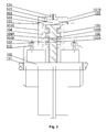
- the device for disintegrating liquid waste is shown in an exploded view on Fig. 1 and in a cross-sectional view of its top portion on Fig. 2 .
- the device comprises a waste processing chamber 100 defined by a housing 101A, 101B with a set of discs 103, 104, 105 rotatable with respect to each other and comprising correlated concentric protrusions 103A, 104A and channels 103B, 104B defining a shear gap 106 and configured to disintegrate liquid waste by cavitation during rotation.
- the liquid waste is provided to an inlet chamber 108 at the central portion of the waste processing chamber 100 via at least one inlet conduit 111 connected to an inlet port 110 formed in the housing 101A.
- the liquid waste disintegrated after passing through the shear gap 106 between the discs 103, 104, 105 is collected from a collecting chamber 107 at the periphery of the waste processing chamber 100 by an outlet conduit 121 connected to an outer port 120 formed in the housing 101A.
- the set of discs comprises stationary discs 104, 105, which are fixed to the housing 101A, 101B or are formed within the internal wall of the housing and a rotatable disc 103 mounted on a shaft 102.
- a collecting chamber 107, shaped as a semi-spiral is formed at the outer periphery of the stationary discs 104, 105 and facilitates collection of the disintegrated liquid waste via the outer port 120.
- the concentric protrusions 103A, 104A and concentric channels 103B, 104B are formed such that after assembly of the device the concentric protrusions 104A of the stationary discs 104, 105 enter into the concentric channels 103B of the rotary disc 103 and vice versa, defining a shear gap 106.
- radial channels 103C, 104C are formed within the concentric protrusions 103A, 104A to facilitate flow of liquid during disintegration from the inlet chamber 108 within the centre of the housing to the collecting chamber 107 at its periphery.
- one stationary disc 104 and one rotatable disc 103 may be provided.
- a pair of stationary discs 104, 105 may be provided, wherein the rotary disc 103 has protrusions and channels formed at its both sides.
- a pair of inlet ports 110 and outlet ports 120 may be provided, one at each housing part 101A, 101 B, to facilitate flow of liquid waste.
- the waste processing chamber 100 is liquid-tight and comprises liquid-tight sealing 131-134, comprising liquid-tight seals 131 at the shaft 102 driving the rotatable disc 103, liquid-tight seals 132 at the inlet ports 110, liquid-tight seals 133 at the outlet ports 120 and liquid-tight seal 134 between the housing parts 101A, 101B.
- the liquid-tight seals 131 have a form of carbon rings, which guarantees their resistance to wear and high temperature at a point of contact with the rotatable shaft.
- an air vent 141 is mounted in the uppermost portion of the waste processing chamber 100. The air vent 141 can be opened during the start phase of the operation of the device to outlet all air from the waste processing chamber 100.
- the shaft 102 on which the rotatable disc 103 is mounted is preferably horizontal, which facilitates equal distribution of liquid waste within the chamber.
- the inlet conduit 111 comprises switchable inlet valve means 112A, 113A for providing to the inlet conduit 111 a liquid waste of a first density from a liquid waste input conduit 112 and/or a liquid of a second density lower than the first density from a supplementary conduit 113.
- the switchable inlet valve means 112A, 113A may comprise separate cut-off valves for the liquid waste input conduit 112 and the supplementary conduit 113 or a single three-way valve for connecting both conduits 112, 113 to the inlet conduit 111.
- the supplementary conduit 113 may provide water or liquid waste of a lower density than the density of the liquid waste provided from conduit 112.
- the liquid waste to be disintegrated enters the inlet chamber 108 via the inlet port 110.
- pressure differences are created within the shear gap.
- the low pressure within the gap falls under vapour point of the waste liquid, thus creating cavitation bubbles.
- the pressure difference also causes self-suction of the liquid and flow of the liquid from the inlet chamber 108 to the collecting chamber 107.
- the disintegration of the liquid waste is therefore effected in two ways. First, larger particles are broken by entering the narrow shear gap into particles of a size smaller than the shear gap width. Second, the broken particles leaving the shear gap are subject to cavitation, which causes their further disintegration into cavitation bubbles.
- the inlet valve means may be switched such that the liquid from the supplementary conduit 113 is input to the processing chamber 100. Since the liquid from the supplementary conduit, preferably water, has a density lower than the density of the liquid waste from the first conduit 112, it causes rinsing of the channels of the discs 103, 104, 105 and reduction of clogging of the shear gap 106. After clogging is removed, the inlet valve means may be switched back to provide the liquid waste from the liquid waste input conduit 112 to the waste processing chamber 100.
- the outlet conduit may comprise switchable outlet valve means 122A, 123A for providing the disintegrated output liquid to a waste output conduit 122 or to a supplementary output conduit 123.
- the output conduits 122, 123 may be coupled with different tanks.
- a sedimentation tank 161 may be coupled with a waste input conduit 112 and the waste output conduit 122, while a water supply tank may be coupled with the supplementary input conduit 113 and the supplementary output conduit 123.
- a water tank instead of a water tank, another sedimentation tank, having waste liquid of a density lower than the sedimentation tank 161, can be used in the installation.
- the clogging may be detected by the operator of the device by simple observation of its operation and the inlet valve mans 112A, 113A may be operated manually.
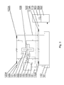
- the clogging can be detected automatically by a sensor 152-154 configured to monitor at least one process parameter of the device and the inlet valve means 112A, 113A may be automatically operated by a controller 151 depending on the monitored process parameter, as shown in Fig. 3 .
- One sensor 153 can be configured to monitor the temperature of the waste processing chamber 100, for example by monitoring the internal temperature or the external temperature of the housing 101A, 101 B, which increase with clogging.
- Another sensor 152 can be configured to monitor the temperature and/or load of an engine 109 driving the rotatable disc 103, which increase with clogging.
- Another sensor 154 can be configured to monitor the density of the liquid in the outlet conduit 120, to detect a threshold density above which clogging may occur.
- the controller 151 may be configured to switch the inlet valve means 112A, 113A such as to provide liquid only from the liquid waste input conduit 112 or only from the supplementary conduit 113, or, alternatively, a mix of liquids from both conduits 112, 113 depending on the monitored process parameter.
- the inlet valve means 112A, 113A are switched to provide to the inlet conduit 111 increased amount of liquid from the supplementary conduit 113 and when reduction of clogging is detected, the inlet valve means 112A, 113A are switched to provide to the inlet conduit 111 increased amount of liquid waste from the liquid waste input conduit 112.
- the device according to the invention operates by processing a part of the liquid waste contained in the sedimentation tank 161, which can be further processed in anaerobic digestion chamber 162, in which biogas is produced and stored in a biogas tank 163. Disintegration of the liquid waste entering the anaerobic digestion chamber 162 promotes the amount of the produced biogas. Therefore, a biogas sensor 164 configured to measure the amount of produced biogas can be connected to the controller 151, and the controller can be configured to control the working cycle, i.e. the amount of time the device operates or the amount of processed liquid waste, depending on the output of the biogas sensor 164, in order to adjust the production of biogas to an optimal amount.
- the optimal amount can be e.g. the amount of biogas which allows filling the biogas tank 163 up to 90% of its maximum capacity.
- the inlet conduit 112 is configured to collect liquid waste from the bottom portion of the sedimentation tank 161, to avoid air content in the liquid waste to be processed.
- the outlet conduit 120 is configured to output the disintegrated liquid waste to the upper portion of the sedimentation tank 161, preferably above the surface of the liquid waste, to facilitate dynamic mixing of the processed liquid waste with the liquid waste in the sedimentation tank
- the width of the shear gap is preferably from 0,4 mm to 0,6 mm.
- the discs 103, 104, 105 are preferably made of corrosion-resistant and cavitation-resistant material, such as stellite.
- the engine 103 preferably rotates the shaft 102 with a speed from 2960 rpm to 3500 rpm.
Landscapes
- Engineering & Computer Science (AREA)
- Food Science & Technology (AREA)
- Environmental & Geological Engineering (AREA)
- Treatment Of Sludge (AREA)
- Processing Of Solid Wastes (AREA)
Priority Applications (2)
| Application Number | Priority Date | Filing Date | Title |
|---|---|---|---|
| EP10461535.6A EP2465610B1 (fr) | 2010-12-20 | 2010-12-20 | Dispositif et procédé pour désintégrer des déchets liquides |
| PL10461535T PL2465610T3 (pl) | 2010-12-20 | 2010-12-20 | Urządzenie i sposób dezintegracji ścieków |
Applications Claiming Priority (1)
| Application Number | Priority Date | Filing Date | Title |
|---|---|---|---|
| EP10461535.6A EP2465610B1 (fr) | 2010-12-20 | 2010-12-20 | Dispositif et procédé pour désintégrer des déchets liquides |
Publications (2)
| Publication Number | Publication Date |
|---|---|
| EP2465610A1 true EP2465610A1 (fr) | 2012-06-20 |
| EP2465610B1 EP2465610B1 (fr) | 2013-05-01 |
Family
ID=44653690
Family Applications (1)
| Application Number | Title | Priority Date | Filing Date |
|---|---|---|---|
| EP10461535.6A Not-in-force EP2465610B1 (fr) | 2010-12-20 | 2010-12-20 | Dispositif et procédé pour désintégrer des déchets liquides |
Country Status (2)
| Country | Link |
|---|---|
| EP (1) | EP2465610B1 (fr) |
| PL (1) | PL2465610T3 (fr) |
Cited By (2)
| Publication number | Priority date | Publication date | Assignee | Title |
|---|---|---|---|---|
| EP3253715A4 (fr) * | 2015-02-03 | 2018-07-18 | Chelan, Inc. | Appareil et procédés de traitement de fluide amélioré |
| EP3467092A4 (fr) * | 2016-05-27 | 2020-04-29 | Nikkan Tokushu Co., Ltd. | Dispositif de broyage de parois ou membranes cellulaires, et procédé de mise en uvre de ce dispositif |
Families Citing this family (1)
| Publication number | Priority date | Publication date | Assignee | Title |
|---|---|---|---|---|
| CN109095638A (zh) * | 2018-08-06 | 2018-12-28 | 华东交通大学 | 一种生物化学污水处理装置 |
Citations (6)
| Publication number | Priority date | Publication date | Assignee | Title |
|---|---|---|---|---|
| US2734685A (en) * | 1956-02-14 | Tomizo saito | ||
| US3996012A (en) | 1973-12-21 | 1976-12-07 | Hans Heinrich Auer | Catalytic reactor having disk-shaped, rotor-stator, reaction surfaces |
| CA1045865A (fr) * | 1976-02-06 | 1979-01-09 | Bauer Bros. Co. (The) | Raffineur a disques aere |
| AT363774B (de) * | 1977-05-31 | 1981-08-25 | Vyzk Ustav Papieru Celulozy | Vorrichtung zum mahlen faseriger suspensionen |
| WO2005030659A1 (fr) | 2003-09-20 | 2005-04-07 | Andreas Schmid | Dispositif et procede pour traiter un milieu tel que des eaux usees, des boues de curage ou analogues |
| EP1985357A1 (fr) | 2007-04-24 | 2008-10-29 | Podwysocki Spolka Jawna | Procédé et appareil pour le traitement de liquides sous des conditions de cavitation |
-
2010
- 2010-12-20 PL PL10461535T patent/PL2465610T3/pl unknown
- 2010-12-20 EP EP10461535.6A patent/EP2465610B1/fr not_active Not-in-force
Patent Citations (6)
| Publication number | Priority date | Publication date | Assignee | Title |
|---|---|---|---|---|
| US2734685A (en) * | 1956-02-14 | Tomizo saito | ||
| US3996012A (en) | 1973-12-21 | 1976-12-07 | Hans Heinrich Auer | Catalytic reactor having disk-shaped, rotor-stator, reaction surfaces |
| CA1045865A (fr) * | 1976-02-06 | 1979-01-09 | Bauer Bros. Co. (The) | Raffineur a disques aere |
| AT363774B (de) * | 1977-05-31 | 1981-08-25 | Vyzk Ustav Papieru Celulozy | Vorrichtung zum mahlen faseriger suspensionen |
| WO2005030659A1 (fr) | 2003-09-20 | 2005-04-07 | Andreas Schmid | Dispositif et procede pour traiter un milieu tel que des eaux usees, des boues de curage ou analogues |
| EP1985357A1 (fr) | 2007-04-24 | 2008-10-29 | Podwysocki Spolka Jawna | Procédé et appareil pour le traitement de liquides sous des conditions de cavitation |
Cited By (3)
| Publication number | Priority date | Publication date | Assignee | Title |
|---|---|---|---|---|
| EP3253715A4 (fr) * | 2015-02-03 | 2018-07-18 | Chelan, Inc. | Appareil et procédés de traitement de fluide amélioré |
| EP3467092A4 (fr) * | 2016-05-27 | 2020-04-29 | Nikkan Tokushu Co., Ltd. | Dispositif de broyage de parois ou membranes cellulaires, et procédé de mise en uvre de ce dispositif |
| US11338300B2 (en) | 2016-05-27 | 2022-05-24 | Nikkan Tokushu Co., Ltd. | Cell wall or cell membrane disrupting device, and method of using the same |
Also Published As
| Publication number | Publication date |
|---|---|
| PL2465610T3 (pl) | 2013-09-30 |
| EP2465610B1 (fr) | 2013-05-01 |
Similar Documents
| Publication | Publication Date | Title |
|---|---|---|
| KR102012525B1 (ko) | 슬러지 파쇄용 믹스장치 | |
| KR101452392B1 (ko) | 혐기성 소화조 | |
| EP2465610B1 (fr) | Dispositif et procédé pour désintégrer des déchets liquides | |
| KR20100112430A (ko) | 스컴제거 장치, 스컴제거 장치가 설치된 혐기소화조 및 혐기소화 시스템 | |
| US7077959B2 (en) | Packaged wastewater treatment unit | |
| US20200030809A1 (en) | Pumping and comminution device, method of comminuting and heating an inflow material, and use of same | |
| KR102479489B1 (ko) | 음식물 쓰레기 처리 장치 | |
| CN103058447B (zh) | 含油污水污泥分离净化一体装置 | |
| CN119080271A (zh) | 一种针对电厂锅炉补给水水源的处理装置 | |
| CN114031179B (zh) | 一种有机物高负荷厌氧消化处理系统 | |
| CN204798978U (zh) | 新型污水泥渣联合处理机 | |
| KR102707664B1 (ko) | 유분 분리 효율이 향상된 복합 원심분리기 | |
| JP4772537B2 (ja) | 汚泥処理システム | |
| CN109647239B (zh) | 一种水力混合装置 | |
| CN203212396U (zh) | 含油污水污泥分离净化一体装置 | |
| CN204265755U (zh) | 用于联合厌氧的具备除浮渣能力的cstr反应器 | |
| KR100988587B1 (ko) | 혐기성 소화조 | |
| CN101348309A (zh) | 厨房固体废弃物和污水一体化处理系统 | |
| CN117902728A (zh) | 一种造纸废水厌氧处理反应器 | |
| KR102298527B1 (ko) | 가스믹서와 분쇄펌프가 결합된 일체식 순환시스템이 장착된 혐기성 소화 장치 및 이의 제어방법 | |
| CN203048724U (zh) | 含油污水污泥分离装置 | |
| CN201309874Y (zh) | 厨房固体废弃物和污水一体化处理系统 | |
| EP1974007B1 (fr) | Cuves de fermentation | |
| CN106669481B (zh) | 一种油砂分离空化器 | |
| CN219098890U (zh) | 水解酸化反应池 |
Legal Events
| Date | Code | Title | Description |
|---|---|---|---|
| PUAI | Public reference made under article 153(3) epc to a published international application that has entered the european phase |
Free format text: ORIGINAL CODE: 0009012 |
|
| AK | Designated contracting states |
Kind code of ref document: A1 Designated state(s): AL AT BE BG CH CY CZ DE DK EE ES FI FR GB GR HR HU IE IS IT LI LT LU LV MC MK MT NL NO PL PT RO RS SE SI SK SM TR |
|
| AX | Request for extension of the european patent |
Extension state: BA ME |
|
| 17P | Request for examination filed |
Effective date: 20120830 |
|
| GRAP | Despatch of communication of intention to grant a patent |
Free format text: ORIGINAL CODE: EPIDOSNIGR1 |
|
| GRAS | Grant fee paid |
Free format text: ORIGINAL CODE: EPIDOSNIGR3 |
|
| GRAA | (expected) grant |
Free format text: ORIGINAL CODE: 0009210 |
|
| AK | Designated contracting states |
Kind code of ref document: B1 Designated state(s): AL AT BE BG CH CY CZ DE DK EE ES FI FR GB GR HR HU IE IS IT LI LT LU LV MC MK MT NL NO PL PT RO RS SE SI SK SM TR |
|
| REG | Reference to a national code |
Ref country code: GB Ref legal event code: FG4D |
|
| REG | Reference to a national code |
Ref country code: AT Ref legal event code: REF Ref document number: 609548 Country of ref document: AT Kind code of ref document: T Effective date: 20130515 Ref country code: CH Ref legal event code: EP |
|
| REG | Reference to a national code |
Ref country code: IE Ref legal event code: FG4D |
|
| REG | Reference to a national code |
Ref country code: RO Ref legal event code: EPE |
|
| REG | Reference to a national code |
Ref country code: DE Ref legal event code: R096 Ref document number: 602010006657 Country of ref document: DE Effective date: 20130627 |
|
| REG | Reference to a national code |
Ref country code: AT Ref legal event code: MK05 Ref document number: 609548 Country of ref document: AT Kind code of ref document: T Effective date: 20130501 |
|
| REG | Reference to a national code |
Ref country code: PL Ref legal event code: T3 |
|
| REG | Reference to a national code |
Ref country code: NL Ref legal event code: VDEP Effective date: 20130501 |
|
| REG | Reference to a national code |
Ref country code: LT Ref legal event code: MG4D |
|
| PG25 | Lapsed in a contracting state [announced via postgrant information from national office to epo] |
Ref country code: LT Free format text: LAPSE BECAUSE OF FAILURE TO SUBMIT A TRANSLATION OF THE DESCRIPTION OR TO PAY THE FEE WITHIN THE PRESCRIBED TIME-LIMIT Effective date: 20130501 Ref country code: AT Free format text: LAPSE BECAUSE OF FAILURE TO SUBMIT A TRANSLATION OF THE DESCRIPTION OR TO PAY THE FEE WITHIN THE PRESCRIBED TIME-LIMIT Effective date: 20130501 Ref country code: GR Free format text: LAPSE BECAUSE OF FAILURE TO SUBMIT A TRANSLATION OF THE DESCRIPTION OR TO PAY THE FEE WITHIN THE PRESCRIBED TIME-LIMIT Effective date: 20130802 Ref country code: IS Free format text: LAPSE BECAUSE OF FAILURE TO SUBMIT A TRANSLATION OF THE DESCRIPTION OR TO PAY THE FEE WITHIN THE PRESCRIBED TIME-LIMIT Effective date: 20130901 Ref country code: NO Free format text: LAPSE BECAUSE OF FAILURE TO SUBMIT A TRANSLATION OF THE DESCRIPTION OR TO PAY THE FEE WITHIN THE PRESCRIBED TIME-LIMIT Effective date: 20130801 Ref country code: SE Free format text: LAPSE BECAUSE OF FAILURE TO SUBMIT A TRANSLATION OF THE DESCRIPTION OR TO PAY THE FEE WITHIN THE PRESCRIBED TIME-LIMIT Effective date: 20130501 Ref country code: PT Free format text: LAPSE BECAUSE OF FAILURE TO SUBMIT A TRANSLATION OF THE DESCRIPTION OR TO PAY THE FEE WITHIN THE PRESCRIBED TIME-LIMIT Effective date: 20130902 Ref country code: ES Free format text: LAPSE BECAUSE OF FAILURE TO SUBMIT A TRANSLATION OF THE DESCRIPTION OR TO PAY THE FEE WITHIN THE PRESCRIBED TIME-LIMIT Effective date: 20130812 Ref country code: SI Free format text: LAPSE BECAUSE OF FAILURE TO SUBMIT A TRANSLATION OF THE DESCRIPTION OR TO PAY THE FEE WITHIN THE PRESCRIBED TIME-LIMIT Effective date: 20130501 Ref country code: FI Free format text: LAPSE BECAUSE OF FAILURE TO SUBMIT A TRANSLATION OF THE DESCRIPTION OR TO PAY THE FEE WITHIN THE PRESCRIBED TIME-LIMIT Effective date: 20130501 |
|
| REG | Reference to a national code |
Ref country code: SK Ref legal event code: T3 Ref document number: E 14558 Country of ref document: SK |
|
| PG25 | Lapsed in a contracting state [announced via postgrant information from national office to epo] |
Ref country code: HR Free format text: LAPSE BECAUSE OF FAILURE TO SUBMIT A TRANSLATION OF THE DESCRIPTION OR TO PAY THE FEE WITHIN THE PRESCRIBED TIME-LIMIT Effective date: 20130501 Ref country code: CY Free format text: LAPSE BECAUSE OF FAILURE TO SUBMIT A TRANSLATION OF THE DESCRIPTION OR TO PAY THE FEE WITHIN THE PRESCRIBED TIME-LIMIT Effective date: 20130501 Ref country code: RS Free format text: LAPSE BECAUSE OF FAILURE TO SUBMIT A TRANSLATION OF THE DESCRIPTION OR TO PAY THE FEE WITHIN THE PRESCRIBED TIME-LIMIT Effective date: 20130501 |
|
| PG25 | Lapsed in a contracting state [announced via postgrant information from national office to epo] |
Ref country code: LV Free format text: LAPSE BECAUSE OF FAILURE TO SUBMIT A TRANSLATION OF THE DESCRIPTION OR TO PAY THE FEE WITHIN THE PRESCRIBED TIME-LIMIT Effective date: 20130501 |
|
| PG25 | Lapsed in a contracting state [announced via postgrant information from national office to epo] |
Ref country code: BE Free format text: LAPSE BECAUSE OF FAILURE TO SUBMIT A TRANSLATION OF THE DESCRIPTION OR TO PAY THE FEE WITHIN THE PRESCRIBED TIME-LIMIT Effective date: 20130501 Ref country code: EE Free format text: LAPSE BECAUSE OF FAILURE TO SUBMIT A TRANSLATION OF THE DESCRIPTION OR TO PAY THE FEE WITHIN THE PRESCRIBED TIME-LIMIT Effective date: 20130501 Ref country code: DK Free format text: LAPSE BECAUSE OF FAILURE TO SUBMIT A TRANSLATION OF THE DESCRIPTION OR TO PAY THE FEE WITHIN THE PRESCRIBED TIME-LIMIT Effective date: 20130501 |
|
| PG25 | Lapsed in a contracting state [announced via postgrant information from national office to epo] |
Ref country code: NL Free format text: LAPSE BECAUSE OF FAILURE TO SUBMIT A TRANSLATION OF THE DESCRIPTION OR TO PAY THE FEE WITHIN THE PRESCRIBED TIME-LIMIT Effective date: 20130501 |
|
| PLBE | No opposition filed within time limit |
Free format text: ORIGINAL CODE: 0009261 |
|
| STAA | Information on the status of an ep patent application or granted ep patent |
Free format text: STATUS: NO OPPOSITION FILED WITHIN TIME LIMIT |
|
| 26N | No opposition filed |
Effective date: 20140204 |
|
| REG | Reference to a national code |
Ref country code: HU Ref legal event code: AG4A Ref document number: E018750 Country of ref document: HU |
|
| REG | Reference to a national code |
Ref country code: DE Ref legal event code: R097 Ref document number: 602010006657 Country of ref document: DE Effective date: 20140204 |
|
| PG25 | Lapsed in a contracting state [announced via postgrant information from national office to epo] |
Ref country code: LU Free format text: LAPSE BECAUSE OF FAILURE TO SUBMIT A TRANSLATION OF THE DESCRIPTION OR TO PAY THE FEE WITHIN THE PRESCRIBED TIME-LIMIT Effective date: 20131220 |
|
| REG | Reference to a national code |
Ref country code: IE Ref legal event code: MM4A |
|
| PG25 | Lapsed in a contracting state [announced via postgrant information from national office to epo] |
Ref country code: IE Free format text: LAPSE BECAUSE OF NON-PAYMENT OF DUE FEES Effective date: 20131220 |
|
| PG25 | Lapsed in a contracting state [announced via postgrant information from national office to epo] |
Ref country code: MC Free format text: LAPSE BECAUSE OF FAILURE TO SUBMIT A TRANSLATION OF THE DESCRIPTION OR TO PAY THE FEE WITHIN THE PRESCRIBED TIME-LIMIT Effective date: 20130501 |
|
| PG25 | Lapsed in a contracting state [announced via postgrant information from national office to epo] |
Ref country code: SM Free format text: LAPSE BECAUSE OF FAILURE TO SUBMIT A TRANSLATION OF THE DESCRIPTION OR TO PAY THE FEE WITHIN THE PRESCRIBED TIME-LIMIT Effective date: 20130501 |
|
| PG25 | Lapsed in a contracting state [announced via postgrant information from national office to epo] |
Ref country code: TR Free format text: LAPSE BECAUSE OF FAILURE TO SUBMIT A TRANSLATION OF THE DESCRIPTION OR TO PAY THE FEE WITHIN THE PRESCRIBED TIME-LIMIT Effective date: 20130501 |
|
| PG25 | Lapsed in a contracting state [announced via postgrant information from national office to epo] |
Ref country code: MK Free format text: LAPSE BECAUSE OF FAILURE TO SUBMIT A TRANSLATION OF THE DESCRIPTION OR TO PAY THE FEE WITHIN THE PRESCRIBED TIME-LIMIT Effective date: 20130501 |
|
| REG | Reference to a national code |
Ref country code: CH Ref legal event code: PL |
|
| PG25 | Lapsed in a contracting state [announced via postgrant information from national office to epo] |
Ref country code: MT Free format text: LAPSE BECAUSE OF FAILURE TO SUBMIT A TRANSLATION OF THE DESCRIPTION OR TO PAY THE FEE WITHIN THE PRESCRIBED TIME-LIMIT Effective date: 20130501 |
|
| PG25 | Lapsed in a contracting state [announced via postgrant information from national office to epo] |
Ref country code: LI Free format text: LAPSE BECAUSE OF NON-PAYMENT OF DUE FEES Effective date: 20141231 Ref country code: CH Free format text: LAPSE BECAUSE OF NON-PAYMENT OF DUE FEES Effective date: 20141231 |
|
| REG | Reference to a national code |
Ref country code: FR Ref legal event code: PLFP Year of fee payment: 6 |
|
| REG | Reference to a national code |
Ref country code: FR Ref legal event code: PLFP Year of fee payment: 7 |
|
| REG | Reference to a national code |
Ref country code: FR Ref legal event code: PLFP Year of fee payment: 8 |
|
| PG25 | Lapsed in a contracting state [announced via postgrant information from national office to epo] |
Ref country code: AL Free format text: LAPSE BECAUSE OF FAILURE TO SUBMIT A TRANSLATION OF THE DESCRIPTION OR TO PAY THE FEE WITHIN THE PRESCRIBED TIME-LIMIT Effective date: 20130501 |
|
| PGFP | Annual fee paid to national office [announced via postgrant information from national office to epo] |
Ref country code: RO Payment date: 20191220 Year of fee payment: 10 Ref country code: CZ Payment date: 20191219 Year of fee payment: 10 Ref country code: SK Payment date: 20191218 Year of fee payment: 10 Ref country code: BG Payment date: 20191218 Year of fee payment: 10 |
|
| PGFP | Annual fee paid to national office [announced via postgrant information from national office to epo] |
Ref country code: FR Payment date: 20191226 Year of fee payment: 10 Ref country code: IT Payment date: 20191219 Year of fee payment: 10 Ref country code: PL Payment date: 20191205 Year of fee payment: 10 |
|
| PGFP | Annual fee paid to national office [announced via postgrant information from national office to epo] |
Ref country code: GB Payment date: 20191227 Year of fee payment: 10 Ref country code: DE Payment date: 20191231 Year of fee payment: 10 Ref country code: HU Payment date: 20200106 Year of fee payment: 10 |
|
| REG | Reference to a national code |
Ref country code: DE Ref legal event code: R119 Ref document number: 602010006657 Country of ref document: DE |
|
| PG25 | Lapsed in a contracting state [announced via postgrant information from national office to epo] |
Ref country code: RO Free format text: LAPSE BECAUSE OF NON-PAYMENT OF DUE FEES Effective date: 20201220 Ref country code: CZ Free format text: LAPSE BECAUSE OF NON-PAYMENT OF DUE FEES Effective date: 20201220 |
|
| GBPC | Gb: european patent ceased through non-payment of renewal fee |
Effective date: 20201220 |
|
| REG | Reference to a national code |
Ref country code: SK Ref legal event code: MM4A Ref document number: E 14558 Country of ref document: SK Effective date: 20201220 |
|
| PG25 | Lapsed in a contracting state [announced via postgrant information from national office to epo] |
Ref country code: FR Free format text: LAPSE BECAUSE OF NON-PAYMENT OF DUE FEES Effective date: 20201231 Ref country code: BG Free format text: LAPSE BECAUSE OF NON-PAYMENT OF DUE FEES Effective date: 20210630 Ref country code: IT Free format text: LAPSE BECAUSE OF NON-PAYMENT OF DUE FEES Effective date: 20201220 Ref country code: HU Free format text: LAPSE BECAUSE OF NON-PAYMENT OF DUE FEES Effective date: 20201221 |
|
| PG25 | Lapsed in a contracting state [announced via postgrant information from national office to epo] |
Ref country code: SK Free format text: LAPSE BECAUSE OF NON-PAYMENT OF DUE FEES Effective date: 20201220 Ref country code: GB Free format text: LAPSE BECAUSE OF NON-PAYMENT OF DUE FEES Effective date: 20201220 Ref country code: DE Free format text: LAPSE BECAUSE OF NON-PAYMENT OF DUE FEES Effective date: 20210701 |
|
| PG25 | Lapsed in a contracting state [announced via postgrant information from national office to epo] |
Ref country code: PL Free format text: LAPSE BECAUSE OF NON-PAYMENT OF DUE FEES Effective date: 20201220 |