EP2465744A2 - Procédé et dispositif de détection de fuites dans des circuits de cylindres de freinage - Google Patents
Procédé et dispositif de détection de fuites dans des circuits de cylindres de freinage Download PDFInfo
- Publication number
- EP2465744A2 EP2465744A2 EP11185654A EP11185654A EP2465744A2 EP 2465744 A2 EP2465744 A2 EP 2465744A2 EP 11185654 A EP11185654 A EP 11185654A EP 11185654 A EP11185654 A EP 11185654A EP 2465744 A2 EP2465744 A2 EP 2465744A2
- Authority
- EP
- European Patent Office
- Prior art keywords
- brake
- pressure
- circuit
- brake fluid
- leak
- Prior art date
- Legal status (The legal status is an assumption and is not a legal conclusion. Google has not performed a legal analysis and makes no representation as to the accuracy of the status listed.)
- Granted
Links
Images
Classifications
-
- B—PERFORMING OPERATIONS; TRANSPORTING
- B60—VEHICLES IN GENERAL
- B60T—VEHICLE BRAKE CONTROL SYSTEMS OR PARTS THEREOF; BRAKE CONTROL SYSTEMS OR PARTS THEREOF, IN GENERAL; ARRANGEMENT OF BRAKING ELEMENTS ON VEHICLES IN GENERAL; PORTABLE DEVICES FOR PREVENTING UNWANTED MOVEMENT OF VEHICLES; VEHICLE MODIFICATIONS TO FACILITATE COOLING OF BRAKES
- B60T17/00—Component parts, details, or accessories of power brake systems not covered by groups B60T8/00, B60T13/00 or B60T15/00, or presenting other characteristic features
- B60T17/18—Safety devices; Monitoring
- B60T17/22—Devices for monitoring or checking brake systems; Signal devices
- B60T17/228—Devices for monitoring or checking brake systems; Signal devices for railway vehicles
-
- B—PERFORMING OPERATIONS; TRANSPORTING
- B60—VEHICLES IN GENERAL
- B60T—VEHICLE BRAKE CONTROL SYSTEMS OR PARTS THEREOF; BRAKE CONTROL SYSTEMS OR PARTS THEREOF, IN GENERAL; ARRANGEMENT OF BRAKING ELEMENTS ON VEHICLES IN GENERAL; PORTABLE DEVICES FOR PREVENTING UNWANTED MOVEMENT OF VEHICLES; VEHICLE MODIFICATIONS TO FACILITATE COOLING OF BRAKES
- B60T17/00—Component parts, details, or accessories of power brake systems not covered by groups B60T8/00, B60T13/00 or B60T15/00, or presenting other characteristic features
- B60T17/18—Safety devices; Monitoring
- B60T17/22—Devices for monitoring or checking brake systems; Signal devices
-
- G—PHYSICS
- G01—MEASURING; TESTING
- G01M—TESTING STATIC OR DYNAMIC BALANCE OF MACHINES OR STRUCTURES; TESTING OF STRUCTURES OR APPARATUS, NOT OTHERWISE PROVIDED FOR
- G01M3/00—Investigating fluid-tightness of structures
- G01M3/02—Investigating fluid-tightness of structures by using fluid or vacuum
- G01M3/26—Investigating fluid-tightness of structures by using fluid or vacuum by measuring rate of loss or gain of fluid, e.g. by pressure-responsive devices, by flow detectors
Definitions
- the invention relates to a method for detecting a leakage in a brake cylinder circuit of one of several brake circuits of a train brake system, a monitoring device for at least one brake circuit of a train brake system for detecting a leak in a brake cylinder circuit and a train brake system with a capability to detect leaks in brake cylinder circuits of individual brake circuits.
- braking systems are known from the prior art, which have brakes that can be designed, for example, as so-called indirect or direct braking.
- a central supply line which is called main air reservoir line
- individual brake circuits are supplied with a brake fluid, usually in the form of compressed air.
- the individual brake circuits have an air reservoir associated with the brake circuit, which serves as a local reservoir for the brake fluid.
- This is fluidly coupled via a main air tank line connection with the main air reservoir line (HBL).
- HBL main air reservoir line
- a relay valve is in each case coupled, which controls a pressure in a brake cylinder circuit. The control of the relay valve via at least one valve of the pilot circuit, which is controlled via a control line.
- Such a brake circuit is usually associated with a bogie of a tractor unit.
- a plurality of brake cylinders are generally present, each braking a brake disc or a wheel on an axle of the bogie.
- the brake cylinders are thus arranged on the bogie in spatial proximity to the wheels of the bogie.
- the brake fluid of the brake circuit is directed to the various brake cylinders via brake pressure lines.
- These brake pressure lines of the brake cylinder circuit are usually formed at least partially as hoses. These are exposed to environmental influences such as mechanical rockfall and / or ice buildup and the like while driving, which can damage the brake pressure lines. Likewise, manipulations due to vandalism can occur.
- a correct operation of the brakes of a train system is safety-relevant for the driving operation of a train system. Since damage or breakage of a brake pressure line of a brake cylinder circuit to a reduced Braking power or a failure of one or even more brake cylinder leads to a bogie, it is desirable to reliably check the availability of the brakes, especially before driving.
- One aspect of such availability testing is to verify that there are no leaks in the brake cylinder circuit of a brake circuit.
- the object of the invention is therefore to provide a method, a monitoring device and a train brake system with which an availability of the individual brake circuits, and in particular a leakage of the individual brake cylinder circuits, detected or leaks in the brake cylinder circuits can be reliably detected.
- the invention is based on the idea to make extensive use of components already installed in the train brake circuits in order to carry out the check. Since leakage in the brake cylinder circuit causes a continuous loss of brake fluid during braking, flow measurement and / or pressure monitoring are apt to detect such leaks.
- the built-in brake cylinder pressure sensors are not suitable for this purpose, as between the pressure sensors, which are installed in the immediate vicinity of the relay valves, and the brake cylinders in are arranged to prevent individual wheels or axles blocking by monitoring a rotational movement of the wheels or axles in relation to the train speed and in a determined overbraking of the wheels or the axle, resulting in a locking of the wheels or the Axle can lead or has led to selectively reduce a pressure in the strand of the brake cylinder circuit in which the anti-skid valve associated brake cylinder are arranged.
- the anti-skid valves are designed so that even with a demolition of a compressed air hose between the anti-skid valve and one of the associated brake cylinder in the brake pressure line, no rapid pressure drop at the arranged between the relay valve and anti-skid valve pressure sensor is to measure. This is even more so, since the brake fluid is nachgeschreibt on the relay valve to maintain the predetermined pressure in the brake cylinder circuit.
- a pressure which is referred to as R-pressure
- the R pressure thus represents a supply pressure with brake fluid, which is applied to the relay valve for supplying the brake cylinder circuit.
- R pressure value On the basis of this R pressure value, a deviation from a specification due to a consumption of brake fluid in the brake cylinder circuit caused by the leakage can be determined by comparison with at least one reference value and thus concluded that there is a leakage. This can be determined particularly well in a static or quasi-static braking state in which the braking request in the brake circuit is no longer changed.
- the method indicates a leak in the event of a deviation outside of a tolerance range and indicates leakage in the event of a match or a deviation within the tolerance range, ie, for example, if a deviation by more than a predefined tolerance limit indicates a leak.
- an embodiment of a method for detecting a leakage in a brake cylinder circuit of one of several brake circuits of a train braking system is proposed in which the brake circuits are supplied with a brake fluid via a main air reservoir line (HBL) and wherein each brake circuit serving as a local reservoir for the brake fluid air reservoir ( R_n), a relay valve for controlling the pressure in the brake cylinder circuit, and a pressure sensor for measuring the supply pressure of the brake fluid applied to the relay valve, referred to as R-pressure
- the method comprising the steps of: measuring the R-pressure (supply pressure) in one , preferably static or quasi-static, braking state, wherein it is provided that the R-pressure with at least one reference value (or more reference values) is compared and depending on the comparison result, a presence of a leak in the brake cylinder circuit of the brake circuit or a Leckfre sity is signaled or displayed.
- the static braking state is understood to be a braking state in which the pressures in the brake circuit no longer change due to the braking request in the respective braking state, provided that all the components function properly.
- a quasi-static braking state a state is considered in which the pressure in the brake circuit no longer changes, at least due to application or release of the brakes, that is to say a buildup or reduction of the brake pressure in the brake cylinder circuit in a fully functional brake circuit. Pressure changes may occur due to tracking brake fluid across the main reservoir conduit in the quasi-static braking condition. During each braking process, brake fluid is consumed, which is used to build up the brake pressure in the brake cylinder circuits and escapes when releasing the brakes from the brake cylinder circuits and thus the brake system is lost long term. After the initiation of a braking operation, therefore, brake fluid is tracked via the main air reservoir line in order to provide sufficient brake fluid in the brake circuits for future braking operations.
- Advantage of the invention is that without a large additional hardware effort a failure of a brake cylinder circuit due to leakage can be determined quickly and reliably, especially after establishing a static or quasi-static braking state.
- measurement data already acquired in conventional brake systems can be used and evaluated in the form of pressure data.
- flow data or other data may alternatively or additionally be used.
- the at least one reference value is an R pressure of the same brake circuit measured in the same, preferably static or quasi-static, braking state, which was measured before the current R pressure. If a loss of brake fluid occurs, a pressure gradient caused by the loss of brake fluid due to the leakage can be determined in the preferably static or quasi-static braking state.
- the evaluation device is designed as the at least one reference value (Pr_N (t i)) or said plurality of reference values of the R-printing of the same brake circuit temporally previously in the same, preferably static or quasi-static, to measure braking state and upon occurrence of a pressure difference between the current R pressure (pR_n (t actual )) and the at least one reference value (pR_n (t i )) whose amount is greater than a preset value, indicating the presence of a leak in the brake cylinder circuit.
- a pressure difference between the reference value, which is an R-pressure value, and the current R-pressure value is formed in a particularly advantageous manner, and the presence of a leak in the brake-cylinder circuit is indicated, if its magnitude deviates from a default value.
- the variable characterizing the brake fluid is then the gradient.
- the at least one reference value or one of the reference values used for the comparison is in this case a value for a tolerable gradient of the quantity relating to the brake fluid. If the R pressure is the quantity relating to the brake fluid, the at least one reference value in this embodiment comprises or is a pressure gradient value.
- the evaluation device is designed to detect additional R pressures of the at least one brake circuit in addition to the current R pressure during the same, preferably static or quasi-static, brake execution and to calculate at least one pressure gradient as the characteristic of the supplying brake fluid size and using a pressure gradient value as the at least one reference value.
- a further embodiment that is measured as the at least one reference value or one of a plurality of reference values R pressure of another similar brake circuit and again between the reference value and the current R-pressure value of the monitored brake circuit, a difference is formed and if there is a deviation from a default value, a presence of a leak is indicated.
- Advantage of this embodiment is that even with a Nachêt of brake fluid on the main air reservoir line, a reliable signal is measured, since in an intact system, the Nachêt leads to a higher pressure rise than in the brake circuit in which continuously consumes brake fluid due to the leakage in the brake cylinder circuit becomes.
- the evaluation device has an input for receiving the at least one reference value or the plurality of reference values, wherein the at least one reference value or the plurality of reference values is an R-pressure or several R-pressures of at least one other similar brake circuit during the same, preferably static or quasi-static , Braking state and / or at the same time with the current R-pressure in the main air reservoir line measured HBL pressure (pMRP (t current )) includes or, and is configured to indicate the presence of a leak in the brake cylinder circuit upon occurrence of a pressure difference between the current R-pressure and the at least one reference value whose magnitude is greater than a preset value.
- pMRP t current
- An increase in the observed pressure difference between the current R-pressure and a reference value representing an R-pressure can be brought about by suppressing make-up of brake fluid into the main air reservoir line and / or a main air reservoir from which the main air reservoir line is fed , This ensures that no subsequent delivery of brake fluid can take place in the brake circuit, so that in a short time the brake fluid present in the brake circuit is determined due to the loss of brake fluid in the brake cylinder circuit via a pressure drop in the R-pressure.
- a pressure drop in the brake circuit via an escape of brake fluid through the main air reservoir line is prevented by a check valve being arranged immediately behind the main air reservoir line connection of the brake circuit, which prevents a backflow of brake fluid into the main air reservoir line.
- An after-delivery of brake fluid can usually be brought about by switching off one or more compressors in a tractor that feed the main air reservoirs serving as reservoirs. Also, the pressure gradients occurring in an existing leak are increased when the make-up is prevented.
- the at least one evaluation device is designed to prevent an infeed of brake fluid into the main air reservoir line and / or a main air reservoir coupled to the main air reservoir line in the, preferably static or quasi-static, braking state and the detection of the current R-pressure after the inhibiting Inject feed.
- the monitoring device when configured to disconnect or at least fluidly disconnect the compressor (s) feeding the main air reservoir line during the check, the measurement of a flow rate or a flow velocity in the supply line of the relay valve is advantageous Embodiment.
- a throttle which reduces a subsequent delivery of brake fluid to the relay valve in front of the pressure sensor for measuring the R pressure.
- a throttle is arranged immediately before or after the check valve, but even before a diversion in the air tank of the brake circuit.
- Other embodiments provide that the throttle is arranged after the branch in the air tank of the brake circuit and thus is seconded between the air tank and the pressure sensor for measuring the R-pressure.
- the throttle may be formed, for example, as a nozzle. However, any other throttling devices known to those skilled in the art can also be used.
- a reliability of the overall system can be increased by detecting additional R pressures of the at least one brake circuit in addition to the current R pressure during the same, preferably static or quasi-static, braking state and for this purpose detecting or receiving simultaneously or temporally coupled measured pressure values of other brake circuits as reference values and comparing the current R-pressure with the at least one reference value comprises evaluating a time R-pressure behavior of the brake circuit during the, preferably quasi-static or static, braking state with at least one pressure behavior of the simultaneously measured or temporally coupled measured reference values.
- a comparison of the R-pressure and here in particular the temporal R-pressure behavior with the R-pressure behavior in one or more similar brake circuits advantageous to unambiguous Way to detect a leak in the brake cylinder circuit.
- a comparison with reference values of several different similar brake circuits instead.
- a comparison of the temporal pressure behavior of different brake circuits can be determined, for example, by determining in each case a difference between a value of the brake circuit to be monitored and a simultaneously or temporally coupled corresponding reference value of another brake circuit. If the difference changes over time, a leak can be deduced from this.
- Time-coupled means in this context that there is a temporal correlation between the detection of the reference value of another brake circuit or a pressure of the main container air line and a corresponding R-pressure value of the brake circuit to be monitored. The temporal correlation is the same for different successively measured R-pressure values and the corresponding reference values within tolerance limits.
- the pressure values are preferably recorded simultaneously in the brake circuit to be monitored and the system which supplies the reference pressure.
- R-pressures of similar brake circuits are used as reference values, the difference between simultaneous or time-coupled pressure values in the brake circuit to be monitored and a reference brake circuit will continuously increase with time in the event of a leak in the brake circuit to be monitored if brake fluid is not pumped into the brake circuits. If an additional delivery takes place, then the temporal pressure behavior of the differences is dependent on the ratio of the loss quantity to the amount of nachge adopted brake fluid. If the loss amount is greater than the amount of brake fluid to be pumped, then an amount of the pressure difference between R-pressures of similar brake circuits detected at the same time or in a time-controlled manner initially increases continuously and finally reaches a maximum value. However, if the amount of nachgeeauten brake fluid is greater than the loss amount, initially the difference in absolute value also increases, then subsequently, after the brake circuit, which is intact, again completely filled and brought to a maximum pressure to fall.
- a train brake system with a corresponding availability monitoring according to the invention or monitoring for leaks in brake cylinder circuits can be implemented in a central evaluation, which can detect the R-pressure values of the individual brake circuits and possibly pressures of the main tank air line.
- the individual brake circuits or groups of brake circuits control and / or monitoring modules are assigned to run the check for functionality or leaks in the brake cylinder circuits for a single or multiple associated brake circuits.
- the evaluation device is designed to detect the size providing the supplying brake fluid during a static or quasi-static braking state.
- the measuring device comprises a pressure sensor for measuring the pressure applied to the relay valve, designated as R-pressure supply pressure of the brake fluid, and the evaluation device is designed as the current size of the supplying brake fluid to the current R-pressure of the at least one brake circuit to capture.
- the at least one evaluation device is designed to receive the at least one reference value and the at least one reference value comprises an R pressure of another brake circuit of the plurality of brake circuits measured in the same, preferably static or quasistatic braking state.
- At least one HBL pressure sensor is arranged on the main air reservoir line and the evaluation unit is designed to detect HBL pressure values (pMRP (t)) of the HBL pressure sensor and the at least one reference value stores an HBL pressure value (pMRP). t actual )) detected at the same time as the current R pressure (pR_n (t actual )).
- the at least one evaluation device is designed to evaluate the current R-pressures of multiple brake circuits and to monitor their leakage in the corresponding brake cylinder circuits.
- the evaluation device has monitoring modules assigned to the individual brake circuits, which each detect and evaluate the current R pressure of the associated brake circuit.
- the evaluation device has monitoring modules assigned to the individual brake circuits, each of which determines a pressure gradient of the brake fluid supplying the relay valve as the characteristic variable.
- the evaluation device is designed to detect further R pressures for the at least one brake circuit in addition to the current R pressure during the same, preferably static or quasistatic, braking state, and to receive reference values detected simultaneously or temporally coupled thereto to detect and comparing the current R-pressure with the at least one reference value and evaluating a temporal R-pressure behavior of the brake circuit during the, preferably quasi-static or static, braking state with a pressure behavior of the same time or time-coupled detected reference values.
- the at least one measuring device comprises a flow velocity measuring device or a flow measuring device.
- a train brake system is developed in various embodiments with the same features as the monitoring device described. This means that developments of the monitoring device are also applied with the same advantages to a train brake system.
- a train brake system thus implements at least one monitoring device.
- the embodiments of the train brake system and the embodiments of the monitoring device are configured to carry out the different described embodiments of the method for detecting a leakage.
- Leakage monitoring can be carried out before starting to drive and / or during braking during driving.
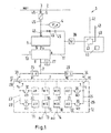
- a brake circuit 1 of a train brake system is shown.
- the brake circuit is supplied via a main air reservoir line 2 with a brake fluid (not shown), usually in the form of compressed air.
- the brake circuit 1 is connected via a main air tank line connection 3 to the main air reservoir line 2.
- Other similar brake circuits (not shown), which are constructed analogously to the brake circuit 1, are also connected to the main air reservoir line 2.
- the various brake circuits of the train brake system are numbered consecutively.
- the brake circuit 1 illustrated here is the nth brake circuit of the train brake system.
- the brake circuit 1 comprises an air tank 4 (R1_n), which serves as a local reservoir for the brake fluid. Fluidically, the air tank 4 is connected to the main air tank line connection 3 via a check valve 5. The check valve 5 prevents brake fluid from the brake circuit 1 can flow back into the main air reservoir line 2.
- the brake circuit 1 further comprises a so-called relay valve 6, which controls a brake fluid pressure c in a brake cylinder circuit 7.
- the relay valve 6 is controlled by a so-called pilot valve 8. This generates a control pressure c v in a pilot line 9.
- the relay valve 6 can be operated as a load-dependent pressure regulator and for this purpose be coupled to a load line 10.
- the brake pressure is influenced as a function of the load of the respective tractor unit, in which the brake circuit 1 is arranged.
- the brake fluid required for generating the brake cylinder circuit pressure c and the energy required for this purpose is supplied to the relay valve 6 via the pressurized brake fluid in a supply line 11 and provided.
- the pressure in the supply line 11, which is a supply pressure, is referred to as R-pressure.
- the supply line 11 and a fluidically connected thereto formed in parallel with the pilot valve 9 line can be interrupted via shut-off valves 46 to disable the brake circuit, for example in the event of a defect.
- the brake cylinder circuit 7 is associated with a bogie 12.
- the bogie comprises two axles 13, 14.
- the axles 13, 14 each have two wheels 15, 16 and 17, 18, respectively.
- Each wheel 15-18 is associated with a brake cylinder 19-22 which actuates brake means (not shown) for braking the respective associated wheel 15-18.
- the brake cylinder circuit 7 is divided into two strands 23, 24.
- the one strand 23 is the one axis 13 and the brake cylinder 19, 20 and the other strand 24 of the other axis 14 and the corresponding brake cylinders 21, 22 assigned.
- the anti-skid valve 25 or 26 assigned to the corresponding axle 13, 14 ensures that the brake circuit cylinder pressure c in the corresponding train 23 is reduced to one Brake cylinder pressure C 1 or in the other strand 24 is lowered to the brake cylinder pressure C 2 , so that a brake pressure in the corresponding brake cylinders 19, 20 and 21, 22 is reduced so far that the wheels 15, 16 and 17, 18 just not To block. Subsequently, the brake pressure C 1 or C 2 is increased again by the slide protection valves 25 and 26 are closed again.
- the brake cylinder circuit pressure c can be measured to ensure that after releasing the brakes in the brake cylinder circuit 7 no more pressure is present, which would signal a concern of the brakes on the wheels 15 - 18 and Driving would lead to overheating of the brakes.
- R pressure the supply pressure
- a pressure sensor 38 For this purpose, a braking state is established and preferably a period of time is waited until the brakes have reached their braking position in the corresponding brake circuit 1.
- the monitoring is preferably carried out at standstill of the vehicle, so that an actual braking effect has no influence on the monitoring. However, the monitoring can also take place during each or selected braking operations while driving.
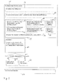
- Fig. 2 is a schematic flow diagram of a method for monitoring the operability of a brake circuit or a plurality of brake circuits of a train brake system described by way of example schematically.
- a braking state is triggered 51.
- a time period is preferably waited 58 to achieve a static or quasi-static braking state.
- a static braking condition is achieved when the pressures in the brake circuit no longer change due to the application of the brakes.
- Quasi-static is a braking state in which change due to a Nach Published of brake fluid, the pressures in the brake circuit, but the pressure in the brake cylinder circuit, provided that it is functional, remains unchanged.
- a current R pressure of the brake circuit n is measured pR_n (t actual ) 53.
- a time measured before the current R-pressure R-pressure of the same brake circuit is detected as a reference value, which is also detected during the static or quasi-static braking state 55.
- R pressures pR_k (t i), pR_I (t i) are detected as reference values 58, or the current time point preceding the main container line pressures pMRP (t i) are detected 59th Be the current time point preceding R-pressures in the brake circuit n at times t i, t i ⁇ t currently detected and this correlated reference values of identical brake circuits or the main air reservoir pipe detected, these are preferably each at the same times t i or within vorfestußer time intervals detected.
- Such simultaneous detection or detection in a predetermined time interval is referred to as time-coupled detection of various pressure values.
- the currently determined R pressure value and at least one of the pressures detected as the reference value are compared 60.
- the comparison result is checked to see if it remains within a specification 61. If this is not the case, there is a leak in the brake circuit. This is signaled accordingly 62. If the specification is met, a leakage is signaled 63.
- the method steps of the evaluation 60, the comparison with the default 61 and the signaling of a leak or leakage 62, 63 can then or at the same time for the other brake circuits of the train brake system. After completing the check, the brake is again released 64.
- a tracking of brake fluid is suppressed 65 via the main air reservoir line, for example, in which a compressor is switched off.
- a dashed line indicates that this method step can be carried out optionally. The same applies to the waiting period 52.
- blocks 55-59 which relate to various method steps for acquiring reference values, are shown in phantom to indicate that they do not all have to be executed in order to execute the method. However, at least one of the method steps must be performed to detect at least one reference value.
- a monitoring device 40 which comprises an evaluation device 41, for example in the form of a program-controlled microcomputer.
- This evaluation device 41 is designed to read out the measurement data of the pressure sensor 38 for determining the R pressure.
- this evaluation device 41 is designed to detect or receive R-pressure values from further brake circuits (not shown) or the main air reservoir line. This is indicated only schematically via a signal line 42.
- a result of the evaluation and signaling of leakage or a leak can take place via a bus line 43, likewise the monitoring device can comprise a signaling device 44, for example in the form of a lamp or a display.
- the monitoring device 40 can be kept centrally in the train unit.
- each brake circuit may comprise its own monitoring device, which is closed together with a central monitoring device of the train brake system.
- Example 1 Comparison with a previously determined in the same brake circuit R pressure value as a reference value
- the condition "that the brake circuit is not separated via a valve from the main air reservoir line” is taken on, since individual brake circuits in this way, for example, in a known defect via the shut-off valves 46 (see Fig. 1 ), and such brake circuits should not be examined for a leak in the brake cylinder circuit.
- a check for a lapse of a period of time may be omitted, unless it is to be measured in a static or quasi-static braking condition.
- Example 2 Checking the current R-pressure against an R-pressure of a similar brake circuit
- a throttle 45 between the main air reservoir line 2 to the pressure sensor 38 for measuring the R pressure (see Fig. 1 ).
- Fig. 1 different positions for the throttle 45 are shown.
- R pressure is determined and evaluated as the quantity relating to the supplying brake fluid.
- Other embodiments may alternatively or additionally detect and evaluate a flow rate or a flow rate of the brake fluid in the supply of the relay valve.
Landscapes
- Engineering & Computer Science (AREA)
- Transportation (AREA)
- Mechanical Engineering (AREA)
- Physics & Mathematics (AREA)
- General Physics & Mathematics (AREA)
- Valves And Accessory Devices For Braking Systems (AREA)
Applications Claiming Priority (1)
| Application Number | Priority Date | Filing Date | Title |
|---|---|---|---|
| DE102010048818A DE102010048818A1 (de) | 2010-10-20 | 2010-10-20 | Verfahren und Vorrichtung zum Erkennen von Lecks in Bremszylinderkreisen |
Publications (3)
| Publication Number | Publication Date |
|---|---|
| EP2465744A2 true EP2465744A2 (fr) | 2012-06-20 |
| EP2465744A3 EP2465744A3 (fr) | 2018-01-24 |
| EP2465744B1 EP2465744B1 (fr) | 2019-01-23 |
Family
ID=44992553
Family Applications (1)
| Application Number | Title | Priority Date | Filing Date |
|---|---|---|---|
| EP11185654.8A Active EP2465744B1 (fr) | 2010-10-20 | 2011-10-18 | Procédé et dispositif de détection de fuites dans des circuits de cylindres de freinage |
Country Status (2)
| Country | Link |
|---|---|
| EP (1) | EP2465744B1 (fr) |
| DE (1) | DE102010048818A1 (fr) |
Cited By (5)
| Publication number | Priority date | Publication date | Assignee | Title |
|---|---|---|---|---|
| CN110696804A (zh) * | 2019-11-14 | 2020-01-17 | 中车株洲电力机车有限公司 | 制动系统的泄漏检测方法及装置 |
| WO2020148257A1 (fr) * | 2019-01-14 | 2020-07-23 | Wabco Gmbh | Procédé pour la surveillance de fuites d'un système à air comprimé |
| CN111912584A (zh) * | 2019-06-25 | 2020-11-10 | 中车大同电力机车有限公司 | 电力机车供气系统用气密性检测装置 |
| CN114577411A (zh) * | 2020-12-02 | 2022-06-03 | 沃尔沃卡车集团 | 气动车辆系统和检测气动车辆系统中的泄漏的方法 |
| CN115791199A (zh) * | 2022-11-10 | 2023-03-14 | 文远苏行(江苏)科技有限公司 | 自动驾驶车辆的制动检测方法、装置 |
Families Citing this family (5)
| Publication number | Priority date | Publication date | Assignee | Title |
|---|---|---|---|---|
| DE102012013521A1 (de) * | 2012-07-06 | 2014-01-09 | Knorr-Bremse Systeme für Schienenfahrzeuge GmbH | Verfahren zur Detektion von Leckagen in einer Bremsdruck führenden Bremsdruckleitung eines Schienenfahrzeugs |
| WO2016028285A1 (fr) * | 2014-08-20 | 2016-02-25 | New York Air Brake, LLC | Indicateur d'entretien de freins |
| US9216724B1 (en) | 2014-08-20 | 2015-12-22 | New York Air Brake, LLC | Brake maintenance indicator |
| DE102015108682A1 (de) * | 2015-06-02 | 2016-12-08 | Knorr-Bremse Systeme für Schienenfahrzeuge GmbH | Vorrichtung und Verfahren zur Überwachung der Luftversorgung eines Schienenfahrzeugs |
| CN106427973B (zh) * | 2016-11-28 | 2020-06-02 | 中车长春轨道客车股份有限公司 | 一种crh380系列动车组中继阀的筛查方法 |
Family Cites Families (4)
| Publication number | Priority date | Publication date | Assignee | Title |
|---|---|---|---|---|
| US1681551A (en) * | 1927-09-30 | 1928-08-21 | Westinghouse Air Brake Co | Leakage-testing device |
| US4847770A (en) * | 1987-11-16 | 1989-07-11 | Pulse Electronics, Inc. | Initial terminal tester |
| EP1634790B1 (fr) * | 2004-09-09 | 2007-10-10 | Few Blankenburg GmbH | Tester l'étanchéité de la conduite principale d'un train |
| US7216552B2 (en) * | 2005-08-25 | 2007-05-15 | International Truck Intellectual Property Company, Llc | Prognostic and diagnostic system for air brakes |
-
2010
- 2010-10-20 DE DE102010048818A patent/DE102010048818A1/de not_active Withdrawn
-
2011
- 2011-10-18 EP EP11185654.8A patent/EP2465744B1/fr active Active
Non-Patent Citations (1)
| Title |
|---|
| None |
Cited By (8)
| Publication number | Priority date | Publication date | Assignee | Title |
|---|---|---|---|---|
| WO2020148257A1 (fr) * | 2019-01-14 | 2020-07-23 | Wabco Gmbh | Procédé pour la surveillance de fuites d'un système à air comprimé |
| CN113302098A (zh) * | 2019-01-14 | 2021-08-24 | 采埃孚商用车系统汉诺威有限公司 | 用于对压缩空气设施进行泄漏监控的方法 |
| US11794713B2 (en) | 2019-01-14 | 2023-10-24 | Zf Cv Systems Hannover Gmbh | Method for leakage monitoring of a compressed-air system |
| CN111912584A (zh) * | 2019-06-25 | 2020-11-10 | 中车大同电力机车有限公司 | 电力机车供气系统用气密性检测装置 |
| CN110696804A (zh) * | 2019-11-14 | 2020-01-17 | 中车株洲电力机车有限公司 | 制动系统的泄漏检测方法及装置 |
| CN110696804B (zh) * | 2019-11-14 | 2020-11-27 | 中车株洲电力机车有限公司 | 制动系统的泄漏检测方法及装置 |
| CN114577411A (zh) * | 2020-12-02 | 2022-06-03 | 沃尔沃卡车集团 | 气动车辆系统和检测气动车辆系统中的泄漏的方法 |
| CN115791199A (zh) * | 2022-11-10 | 2023-03-14 | 文远苏行(江苏)科技有限公司 | 自动驾驶车辆的制动检测方法、装置 |
Also Published As
| Publication number | Publication date |
|---|---|
| EP2465744A3 (fr) | 2018-01-24 |
| DE102010048818A1 (de) | 2012-04-26 |
| EP2465744B1 (fr) | 2019-01-23 |
Similar Documents
| Publication | Publication Date | Title |
|---|---|---|
| EP2465744B1 (fr) | Procédé et dispositif de détection de fuites dans des circuits de cylindres de freinage | |
| EP2870039B1 (fr) | Procédé de détection de fuites dans une conduite de pression de freinage, guidant une pression de freinage, d'un véhicule ferroviaire | |
| EP2288523B1 (fr) | Dispositif de contrôle destiné à contrôler des systèmes d'un véhicule | |
| DE3990898C2 (de) | Druckluftbremsensteuerungssystem | |
| EP2753526B1 (fr) | Procédé de surveillance d'un dispositif de sablage | |
| EP3650292B1 (fr) | Procédé de vérification fonctionnelle d'un système de freinage électronique actionné par fluide sous pression d'un véhicule | |
| DE102008045712A1 (de) | Elektropneumatische Bremseinrichtung sowie Verfahren zum Betrieb derselben | |
| DE102011100726A1 (de) | Verfahren und Vorrichtung zum Überwachen des Bremsbelagverschleißes und Lüftspiels einer Betriebsbremse in Kraftfahrzeugen | |
| EP3286051B1 (fr) | Arrangement de frein de parking pour véhicules | |
| DE102007025835B4 (de) | Diagnose von Leckagen an Druckluftsystemen, insbesondere in Nutzfahrzeugen | |
| DE102018123750A1 (de) | Elektropneumatische Anhängersteuerventileinheit für Nordamerika | |
| DE102012023509A1 (de) | Verfahren zur Regelung oder Einstellung eines Reifenfülldrucks an Fahrzeugreifen und Reifenfülldruck-Einstellvorrichtung | |
| DE102012004892A1 (de) | Beobachter für einen Bremsaktuatordruck | |
| DE102012009185A1 (de) | Verfahren und Einrichtung zum Betrieb von Druckluft-Bremsen | |
| DE102015121480A1 (de) | Verfahren zur Detektion und Kompensation einer Leckage in einer Bremsvorrichtung | |
| EP1995140B1 (fr) | Procédé pour vérifier l'étanchéité d'un système à air comprimé et dispositif électronique pour ledit procédé | |
| EP3119650A2 (fr) | Système de frein pneumatique pour véhicule ferroviaire | |
| EP2724903A2 (fr) | Dispositif de freinage pour machines de travail et procédé d'actionnement du dispositif de freinage | |
| EP2547568A1 (fr) | Procédé et dispositif permettant de détecter la longueur d'un train | |
| DE102021109209A1 (de) | Prüfablauf für die Bremsanlage | |
| DE10337815A1 (de) | Verfahren zur Prüfung von pneumatischen und/oder hydraulischen Bremsen an Schienenfahrzeugen sowie Prüfeinrichtung für pneumatische und/oder hydraulische Bremsanlagen von Schienenfahrzeugen | |
| EP2539183A1 (fr) | Procédé de surveillance de systèmes du véhicule lors de travaux de maintenance sur le véhicule | |
| DE10029125A1 (de) | Alarmeinrichtung für eine druckluftgesteuerte Bremsanlage eines Fahrzeugs | |
| EP1312524B1 (fr) | Méthode d'opération d'une système de freinage électriquement contrôlée | |
| WO2015090701A1 (fr) | Procédé pour faire fonctionner un système de freinage et système de freinage pour véhicule automobile |
Legal Events
| Date | Code | Title | Description |
|---|---|---|---|
| PUAI | Public reference made under article 153(3) epc to a published international application that has entered the european phase |
Free format text: ORIGINAL CODE: 0009012 |
|
| AK | Designated contracting states |
Kind code of ref document: A2 Designated state(s): AL AT BE BG CH CY CZ DE DK EE ES FI FR GB GR HR HU IE IS IT LI LT LU LV MC MK MT NL NO PL PT RO RS SE SI SK SM TR |
|
| AX | Request for extension of the european patent |
Extension state: BA ME |
|
| PUAL | Search report despatched |
Free format text: ORIGINAL CODE: 0009013 |
|
| AK | Designated contracting states |
Kind code of ref document: A3 Designated state(s): AL AT BE BG CH CY CZ DE DK EE ES FI FR GB GR HR HU IE IS IT LI LT LU LV MC MK MT NL NO PL PT RO RS SE SI SK SM TR |
|
| AX | Request for extension of the european patent |
Extension state: BA ME |
|
| RIC1 | Information provided on ipc code assigned before grant |
Ipc: B60T 17/22 20060101AFI20171219BHEP |
|
| STAA | Information on the status of an ep patent application or granted ep patent |
Free format text: STATUS: REQUEST FOR EXAMINATION WAS MADE |
|
| 17P | Request for examination filed |
Effective date: 20180417 |
|
| RBV | Designated contracting states (corrected) |
Designated state(s): AL AT BE BG CH CY CZ DE DK EE ES FI FR GB GR HR HU IE IS IT LI LT LU LV MC MK MT NL NO PL PT RO RS SE SI SK SM TR |
|
| GRAP | Despatch of communication of intention to grant a patent |
Free format text: ORIGINAL CODE: EPIDOSNIGR1 |
|
| STAA | Information on the status of an ep patent application or granted ep patent |
Free format text: STATUS: GRANT OF PATENT IS INTENDED |
|
| INTG | Intention to grant announced |
Effective date: 20180809 |
|
| RAP1 | Party data changed (applicant data changed or rights of an application transferred) |
Owner name: BOMBARDIER TRANSPORTATION GMBH |
|
| GRAS | Grant fee paid |
Free format text: ORIGINAL CODE: EPIDOSNIGR3 |
|
| GRAA | (expected) grant |
Free format text: ORIGINAL CODE: 0009210 |
|
| STAA | Information on the status of an ep patent application or granted ep patent |
Free format text: STATUS: THE PATENT HAS BEEN GRANTED |
|
| AK | Designated contracting states |
Kind code of ref document: B1 Designated state(s): AL AT BE BG CH CY CZ DE DK EE ES FI FR GB GR HR HU IE IS IT LI LT LU LV MC MK MT NL NO PL PT RO RS SE SI SK SM TR |
|
| REG | Reference to a national code |
Ref country code: GB Ref legal event code: FG4D Free format text: NOT ENGLISH |
|
| REG | Reference to a national code |
Ref country code: CH Ref legal event code: EP |
|
| REG | Reference to a national code |
Ref country code: AT Ref legal event code: REF Ref document number: 1091215 Country of ref document: AT Kind code of ref document: T Effective date: 20190215 |
|
| REG | Reference to a national code |
Ref country code: IE Ref legal event code: FG4D Free format text: LANGUAGE OF EP DOCUMENT: GERMAN |
|
| REG | Reference to a national code |
Ref country code: DE Ref legal event code: R096 Ref document number: 502011015311 Country of ref document: DE |
|
| REG | Reference to a national code |
Ref country code: CH Ref legal event code: NV Representative=s name: PATENTANWALT DIPL.-ING. (UNI.) WOLFGANG HEISEL, CH |
|
| REG | Reference to a national code |
Ref country code: NL Ref legal event code: MP Effective date: 20190123 |
|
| PG25 | Lapsed in a contracting state [announced via postgrant information from national office to epo] |
Ref country code: NL Free format text: LAPSE BECAUSE OF FAILURE TO SUBMIT A TRANSLATION OF THE DESCRIPTION OR TO PAY THE FEE WITHIN THE PRESCRIBED TIME-LIMIT Effective date: 20190123 |
|
| PG25 | Lapsed in a contracting state [announced via postgrant information from national office to epo] |
Ref country code: PT Free format text: LAPSE BECAUSE OF FAILURE TO SUBMIT A TRANSLATION OF THE DESCRIPTION OR TO PAY THE FEE WITHIN THE PRESCRIBED TIME-LIMIT Effective date: 20190523 Ref country code: SE Free format text: LAPSE BECAUSE OF FAILURE TO SUBMIT A TRANSLATION OF THE DESCRIPTION OR TO PAY THE FEE WITHIN THE PRESCRIBED TIME-LIMIT Effective date: 20190123 Ref country code: ES Free format text: LAPSE BECAUSE OF FAILURE TO SUBMIT A TRANSLATION OF THE DESCRIPTION OR TO PAY THE FEE WITHIN THE PRESCRIBED TIME-LIMIT Effective date: 20190123 Ref country code: PL Free format text: LAPSE BECAUSE OF FAILURE TO SUBMIT A TRANSLATION OF THE DESCRIPTION OR TO PAY THE FEE WITHIN THE PRESCRIBED TIME-LIMIT Effective date: 20190123 Ref country code: LT Free format text: LAPSE BECAUSE OF FAILURE TO SUBMIT A TRANSLATION OF THE DESCRIPTION OR TO PAY THE FEE WITHIN THE PRESCRIBED TIME-LIMIT Effective date: 20190123 Ref country code: NO Free format text: LAPSE BECAUSE OF FAILURE TO SUBMIT A TRANSLATION OF THE DESCRIPTION OR TO PAY THE FEE WITHIN THE PRESCRIBED TIME-LIMIT Effective date: 20190423 Ref country code: FI Free format text: LAPSE BECAUSE OF FAILURE TO SUBMIT A TRANSLATION OF THE DESCRIPTION OR TO PAY THE FEE WITHIN THE PRESCRIBED TIME-LIMIT Effective date: 20190123 |
|
| PG25 | Lapsed in a contracting state [announced via postgrant information from national office to epo] |
Ref country code: IS Free format text: LAPSE BECAUSE OF FAILURE TO SUBMIT A TRANSLATION OF THE DESCRIPTION OR TO PAY THE FEE WITHIN THE PRESCRIBED TIME-LIMIT Effective date: 20190523 Ref country code: BG Free format text: LAPSE BECAUSE OF FAILURE TO SUBMIT A TRANSLATION OF THE DESCRIPTION OR TO PAY THE FEE WITHIN THE PRESCRIBED TIME-LIMIT Effective date: 20190423 Ref country code: RS Free format text: LAPSE BECAUSE OF FAILURE TO SUBMIT A TRANSLATION OF THE DESCRIPTION OR TO PAY THE FEE WITHIN THE PRESCRIBED TIME-LIMIT Effective date: 20190123 Ref country code: HR Free format text: LAPSE BECAUSE OF FAILURE TO SUBMIT A TRANSLATION OF THE DESCRIPTION OR TO PAY THE FEE WITHIN THE PRESCRIBED TIME-LIMIT Effective date: 20190123 Ref country code: LV Free format text: LAPSE BECAUSE OF FAILURE TO SUBMIT A TRANSLATION OF THE DESCRIPTION OR TO PAY THE FEE WITHIN THE PRESCRIBED TIME-LIMIT Effective date: 20190123 Ref country code: GR Free format text: LAPSE BECAUSE OF FAILURE TO SUBMIT A TRANSLATION OF THE DESCRIPTION OR TO PAY THE FEE WITHIN THE PRESCRIBED TIME-LIMIT Effective date: 20190424 |
|
| REG | Reference to a national code |
Ref country code: DE Ref legal event code: R097 Ref document number: 502011015311 Country of ref document: DE |
|
| PG25 | Lapsed in a contracting state [announced via postgrant information from national office to epo] |
Ref country code: SK Free format text: LAPSE BECAUSE OF FAILURE TO SUBMIT A TRANSLATION OF THE DESCRIPTION OR TO PAY THE FEE WITHIN THE PRESCRIBED TIME-LIMIT Effective date: 20190123 Ref country code: AL Free format text: LAPSE BECAUSE OF FAILURE TO SUBMIT A TRANSLATION OF THE DESCRIPTION OR TO PAY THE FEE WITHIN THE PRESCRIBED TIME-LIMIT Effective date: 20190123 Ref country code: EE Free format text: LAPSE BECAUSE OF FAILURE TO SUBMIT A TRANSLATION OF THE DESCRIPTION OR TO PAY THE FEE WITHIN THE PRESCRIBED TIME-LIMIT Effective date: 20190123 Ref country code: DK Free format text: LAPSE BECAUSE OF FAILURE TO SUBMIT A TRANSLATION OF THE DESCRIPTION OR TO PAY THE FEE WITHIN THE PRESCRIBED TIME-LIMIT Effective date: 20190123 Ref country code: CZ Free format text: LAPSE BECAUSE OF FAILURE TO SUBMIT A TRANSLATION OF THE DESCRIPTION OR TO PAY THE FEE WITHIN THE PRESCRIBED TIME-LIMIT Effective date: 20190123 Ref country code: RO Free format text: LAPSE BECAUSE OF FAILURE TO SUBMIT A TRANSLATION OF THE DESCRIPTION OR TO PAY THE FEE WITHIN THE PRESCRIBED TIME-LIMIT Effective date: 20190123 |
|
| PG25 | Lapsed in a contracting state [announced via postgrant information from national office to epo] |
Ref country code: SM Free format text: LAPSE BECAUSE OF FAILURE TO SUBMIT A TRANSLATION OF THE DESCRIPTION OR TO PAY THE FEE WITHIN THE PRESCRIBED TIME-LIMIT Effective date: 20190123 |
|
| PLBE | No opposition filed within time limit |
Free format text: ORIGINAL CODE: 0009261 |
|
| STAA | Information on the status of an ep patent application or granted ep patent |
Free format text: STATUS: NO OPPOSITION FILED WITHIN TIME LIMIT |
|
| 26N | No opposition filed |
Effective date: 20191024 |
|
| PG25 | Lapsed in a contracting state [announced via postgrant information from national office to epo] |
Ref country code: SI Free format text: LAPSE BECAUSE OF FAILURE TO SUBMIT A TRANSLATION OF THE DESCRIPTION OR TO PAY THE FEE WITHIN THE PRESCRIBED TIME-LIMIT Effective date: 20190123 |
|
| PG25 | Lapsed in a contracting state [announced via postgrant information from national office to epo] |
Ref country code: TR Free format text: LAPSE BECAUSE OF FAILURE TO SUBMIT A TRANSLATION OF THE DESCRIPTION OR TO PAY THE FEE WITHIN THE PRESCRIBED TIME-LIMIT Effective date: 20190123 |
|
| PG25 | Lapsed in a contracting state [announced via postgrant information from national office to epo] |
Ref country code: MC Free format text: LAPSE BECAUSE OF FAILURE TO SUBMIT A TRANSLATION OF THE DESCRIPTION OR TO PAY THE FEE WITHIN THE PRESCRIBED TIME-LIMIT Effective date: 20190123 |
|
| PG25 | Lapsed in a contracting state [announced via postgrant information from national office to epo] |
Ref country code: LU Free format text: LAPSE BECAUSE OF NON-PAYMENT OF DUE FEES Effective date: 20191018 |
|
| REG | Reference to a national code |
Ref country code: BE Ref legal event code: MM Effective date: 20191031 |
|
| PG25 | Lapsed in a contracting state [announced via postgrant information from national office to epo] |
Ref country code: BE Free format text: LAPSE BECAUSE OF NON-PAYMENT OF DUE FEES Effective date: 20191031 |
|
| PG25 | Lapsed in a contracting state [announced via postgrant information from national office to epo] |
Ref country code: IE Free format text: LAPSE BECAUSE OF NON-PAYMENT OF DUE FEES Effective date: 20191018 |
|
| PG25 | Lapsed in a contracting state [announced via postgrant information from national office to epo] |
Ref country code: CY Free format text: LAPSE BECAUSE OF FAILURE TO SUBMIT A TRANSLATION OF THE DESCRIPTION OR TO PAY THE FEE WITHIN THE PRESCRIBED TIME-LIMIT Effective date: 20190123 |
|
| PG25 | Lapsed in a contracting state [announced via postgrant information from national office to epo] |
Ref country code: MT Free format text: LAPSE BECAUSE OF FAILURE TO SUBMIT A TRANSLATION OF THE DESCRIPTION OR TO PAY THE FEE WITHIN THE PRESCRIBED TIME-LIMIT Effective date: 20190123 Ref country code: HU Free format text: LAPSE BECAUSE OF FAILURE TO SUBMIT A TRANSLATION OF THE DESCRIPTION OR TO PAY THE FEE WITHIN THE PRESCRIBED TIME-LIMIT; INVALID AB INITIO Effective date: 20111018 |
|
| PG25 | Lapsed in a contracting state [announced via postgrant information from national office to epo] |
Ref country code: MK Free format text: LAPSE BECAUSE OF FAILURE TO SUBMIT A TRANSLATION OF THE DESCRIPTION OR TO PAY THE FEE WITHIN THE PRESCRIBED TIME-LIMIT Effective date: 20190123 |
|
| P01 | Opt-out of the competence of the unified patent court (upc) registered |
Effective date: 20230822 |
|
| REG | Reference to a national code |
Ref country code: CH Ref legal event code: U11 Free format text: ST27 STATUS EVENT CODE: U-0-0-U10-U11 (AS PROVIDED BY THE NATIONAL OFFICE) Effective date: 20251101 |
|
| PGFP | Annual fee paid to national office [announced via postgrant information from national office to epo] |
Ref country code: DE Payment date: 20251021 Year of fee payment: 15 |
|
| PGFP | Annual fee paid to national office [announced via postgrant information from national office to epo] |
Ref country code: GB Payment date: 20251022 Year of fee payment: 15 |
|
| PGFP | Annual fee paid to national office [announced via postgrant information from national office to epo] |
Ref country code: AT Payment date: 20251022 Year of fee payment: 15 |
|
| PGFP | Annual fee paid to national office [announced via postgrant information from national office to epo] |
Ref country code: IT Payment date: 20251024 Year of fee payment: 15 |
|
| PGFP | Annual fee paid to national office [announced via postgrant information from national office to epo] |
Ref country code: FR Payment date: 20251030 Year of fee payment: 15 |
|
| PGFP | Annual fee paid to national office [announced via postgrant information from national office to epo] |
Ref country code: CH Payment date: 20251101 Year of fee payment: 15 |