EP2465766A1 - Balanceüberwachungsgerät für eine schwimmende struktur - Google Patents
Balanceüberwachungsgerät für eine schwimmende struktur Download PDFInfo
- Publication number
- EP2465766A1 EP2465766A1 EP09848308A EP09848308A EP2465766A1 EP 2465766 A1 EP2465766 A1 EP 2465766A1 EP 09848308 A EP09848308 A EP 09848308A EP 09848308 A EP09848308 A EP 09848308A EP 2465766 A1 EP2465766 A1 EP 2465766A1
- Authority
- EP
- European Patent Office
- Prior art keywords
- driving shaft
- driving
- shaft
- eccentric rotating
- shafts
- Prior art date
- Legal status (The legal status is an assumption and is not a legal conclusion. Google has not performed a legal analysis and makes no representation as to the accuracy of the status listed.)
- Granted
Links
Images



Classifications
-
- B—PERFORMING OPERATIONS; TRANSPORTING
- B63—SHIPS OR OTHER WATERBORNE VESSELS; RELATED EQUIPMENT
- B63B—SHIPS OR OTHER WATERBORNE VESSELS; EQUIPMENT FOR SHIPPING
- B63B39/00—Equipment to decrease pitch, roll, or like unwanted vessel movements; Apparatus for indicating vessel attitude
- B63B39/02—Equipment to decrease pitch, roll, or like unwanted vessel movements; Apparatus for indicating vessel attitude to decrease vessel movements by displacement of masses
-
- B—PERFORMING OPERATIONS; TRANSPORTING
- B63—SHIPS OR OTHER WATERBORNE VESSELS; RELATED EQUIPMENT
- B63B—SHIPS OR OTHER WATERBORNE VESSELS; EQUIPMENT FOR SHIPPING
- B63B35/00—Vessels or similar floating structures specially adapted for specific purposes and not otherwise provided for
- B63B35/44—Floating buildings, stores, drilling platforms, or workshops, e.g. carrying water-oil separating devices
-
- B—PERFORMING OPERATIONS; TRANSPORTING
- B63—SHIPS OR OTHER WATERBORNE VESSELS; RELATED EQUIPMENT
- B63B—SHIPS OR OTHER WATERBORNE VESSELS; EQUIPMENT FOR SHIPPING
- B63B39/00—Equipment to decrease pitch, roll, or like unwanted vessel movements; Apparatus for indicating vessel attitude
- B63B39/005—Equipment to decrease ship's vibrations produced externally to the ship, e.g. wave-induced vibrations
-
- B—PERFORMING OPERATIONS; TRANSPORTING
- B63—SHIPS OR OTHER WATERBORNE VESSELS; RELATED EQUIPMENT
- B63B—SHIPS OR OTHER WATERBORNE VESSELS; EQUIPMENT FOR SHIPPING
- B63B39/00—Equipment to decrease pitch, roll, or like unwanted vessel movements; Apparatus for indicating vessel attitude
- B63B39/04—Equipment to decrease pitch, roll, or like unwanted vessel movements; Apparatus for indicating vessel attitude to decrease vessel movements by using gyroscopes directly
-
- B—PERFORMING OPERATIONS; TRANSPORTING
- B63—SHIPS OR OTHER WATERBORNE VESSELS; RELATED EQUIPMENT
- B63B—SHIPS OR OTHER WATERBORNE VESSELS; EQUIPMENT FOR SHIPPING
- B63B43/00—Improving safety of vessels, e.g. damage control, not otherwise provided for
- B63B43/02—Improving safety of vessels, e.g. damage control, not otherwise provided for reducing risk of capsizing or sinking
- B63B43/04—Improving safety of vessels, e.g. damage control, not otherwise provided for reducing risk of capsizing or sinking by improving stability
- B63B43/08—Improving safety of vessels, e.g. damage control, not otherwise provided for reducing risk of capsizing or sinking by improving stability by transfer of solid ballast
Definitions
- the present invention relates to a balance maintaining equipment for a floating body, and more particularly, to a balance maintaining equipment capable of maintaining the balance of a floating body which floats in fluid, for example, a mobile harbor which is moored on the sea remote from land to load and unload cargos.
- a case in which the balance of a floating body floating in fluid should be maintained to guarantee the stability of the floating body exists in a variety of industrial fields.
- the balance of a vessel or mobile harbor needs to be maintained to guarantee the stability of the vessel or mobile harbor.
- marine transportation using a vessel as means for transporting goods to a remote place consumes a smaller amount of energy and requires a smaller transportation cost than other transportation means. Therefore, a large percentage of international trades rely on the marine transportation.
- a large-sized vessel has been used.
- the volume of traffic may be increased to secure the economical efficiency of the transportation. Accordingly, a demand for a harbor including a mooring system capable of mooring a large vessel and a loading/unloading facility is more and more increasing.
- Such a floating body is inevitably rolled by an external or internal cause in fluid.
- a roll occurring in the floating body for example, a roll which is continuously caused by an influence of winds, surges, or tides in a mobile harbor may have a serious effect upon the stability of the floating body. It is, therefore, an object of the present invention to provide a balance maintaining equipment for a floating body capable of reducing or removing the roll in order to stably perform an operation.
- a balance maintaining equipment for a floating body includes: a driving device for rotating a driving shaft; a first eccentric rotating body positioned at one side of the driving device, connected to the driving shaft, and rotated around the driving shaft by the rotation of the driving shaft; and a second eccentric rotating body positioned at the other side of the driving device, connected to the driving shaft, and rotated around the driving shaft by the rotation of the driving shaft, while having a phase difference of 180 degrees from the rotation of the first eccentric rotating body.
- the driving shaft is formed to expand or contract in a direction from the one side to the other side or from the other side to the one side.
- the shafts in the respective stages include a spline shaft or a shaft having a cross-sectional surface formed in a polygonal shape.
- the length of the driving shaft expanded or contacted in the direction of the one side is equal to that of the driving shaft expanded or contracted in the direction of the other side.
- the balance maintaining equipment further includes a first frame having a rotation region of the first eccentric rotating body, supporting the one-side of the driving shaft, and moved together with the shaft of the driving shaft when the driving shaft is expanded or contracted; and a second frame having a rotation region of the second eccentric rotating body, supporting the other-side of the driving shaft, and moved together with the shaft of the driving shaft when the driving shaft is expanded or contracted.
- the balance maintaining equipment further includes guide rails for guiding the first and second frames, respectively, wherein the first and second frames are formed to move along the guide rails, respectively.
- first and second eccentric rotating bodies include first and second rotating shafts having one ends coupled to the driving shaft, and first and second mass bodies coupled to the other ends of the first and second rotating shafts, respectively.
- each of the first and second rotating shafts is formed by combining multi-stage shafts having different diameters wherein a shaft in each stage is expanded and contracted.
- a balance maintaining equipment for a floating body includes: a first driving device for rotating a first driving shaft; a first eccentric rotating body positioned at one side of the first driving device, having one end connected to the first driving shaft, and rotated around the first driving shaft by the rotation of the first driving shaft; a second driving device for rotating a second driving shaft; and a second eccentric rotating body positioned at the other side of the second driving device, having one end connected to the second driving shaft, and rotated around the second driving shaft by the rotation of the second driving shaft, while having a phase difference of 180 degrees from the rotation of the first eccentric rotating body.
- the balance maintaining equipment further includes: a first frame for housing and supporting the first driving device and the first driving shaft; a second frame for housing and supporting the second driving device and the second driving shaft; and a transferring device for transferring the first and second frames in a direction perpendicular to a plane along which the first and second eccentric rotating shafts are rotated.
- the balance maintaining equipment further includes guide rails for guiding the first and second frames, respectively, wherein the first and second frames are moved along the guide rails, respectively.
- the transfer distances of the first and second driving devices are equal to each other.
- first and second eccentric rotating bodies include, first and second rotating shafts having one ends coupled to the first and second driving shafts, respectively, and first and second mass bodies coupled to the other ends of the first and second rotating shafts, respectively.
- the driving device may include a motor, a gear body, and a decelerator.
- the balance maintaining equipment for the floating body in accordance with the embodiments of the present invention may reduce or remove a roll of the floating body floating in fluid. For example, in a mobile harbor performing an operation while floating on the sea, it is possible to reduce or remove a roll of the mobile harbor caused by winds, surges, or tides.
- the stability of the floating body may be guaranteed, and facilities and operators inside the floating body may be protected.
- the operation of the mobile harbor may be stably performed, and the stability of the operators working in the mobile harbor may be guaranteed.
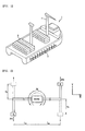
- Fig. 1 is a conceptual diagram of a mobile harbor
- Fig. 2 is a conceptual diagram illustrating the principle of a balance maintaining equipment in a floating body in accordance with embodiments of the present invention
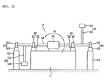
- Fig. 3 is a front view of a balance maintaining equipment for a floating body in accordance with a first embodiment of the present invention
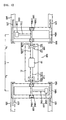
- Fig. 4 is a front view of a balance maintaining equipment for a floating body in accordance with a second embodiment of the present invention.
- Fig. 5 is a plan view of the balance maintaining equipment of the floating body in accordance with the second embodiment of the present invention.
- Fig. 6 is a front view of a balance maintaining equipment for a floating body in accordance with a third embodiment of the present invention.
- Fig. 7 is a plan view of the balance maintaining equipment of the floating body in accordance with the third embodiment of the present invention.
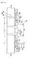
- Fig. 8 is a front view of a balance maintaining equipment for a floating body in accordance with a fourth embodiment of the present invention.
- a balance maintaining equipment for a floating body in accordance with embodiments of the present invention may be applied to all bodies floating in fluid.
- a floating body on the sea for example, a mobile harbor will be specifically described.
- the mobile harbor will be taken as a representative example of bodies floating in fluid, and the floating body may include a mobile harbor, a vessel, and a partial unit such as an apparatus floating in fluid.
- Fig. 1 is a conceptual diagram of a mobile harbor as an example of a floating body.
- Fig. 2 is a conceptual diagram illustrating the principle of a balance maintaining equipment in the floating body in accordance with the present invention.
- Figs. 3 to 8 are diagrams illustrating specific embodiments of the present invention.
- the mobile harbor 1 is available to load and unload cargos 3 on the sea. That is, the mobile harbor 1 is docked with a vessel (not illustrated) such as a container vessel through a docking system 5 on the sea, and loads the cargos 3 on the vessel or unloads cargos from the vessel by using a loading and unloading system 7.
- a vessel such as a container vessel through a docking system 5 on the sea
- the mobile harbor 1 may roll during the loading and unloading operations. Due to the rolling, there occur difficulties in performing the loading and unloading operations. Therefore, the mobile harbor 1 needs a balance maintaining equipment for maintaining the balance of the mobile harbor 1.
- the wave of the surge may be set to a surge period of five seconds, more or less in design of a general vessel.
- Such a period may be set differently depending on the structures of vessels and the operation environments of the vessels. In the embodiments of the present invention, the period may be set differently depending on the operation position of the mobile harbor 1 or the like.
- the magnitude of the moment M may be calculated as expressed below.
- m represents the mass of the mass bodies
- r represents a radius of gyration
- ⁇ represents an angular velocity
- L represents a distance from the center
- lower subscripts A and B represents the respective mass bodies.
- the moment M has a corresponding period and direction depending on the rotation periods of the mass bodies A and B. If the period of the moment M is rendered to adapt to the roll period of the floating body caused by rolling factors such as surges, tides or winds, but to produce a moment by which the moment M is balanced in the opposite direction to the rolling of the floating body, it is possible to substantially reduce or remove the rolling of the floating body.
- the generation or generation period of the moment M needs to be changed.
- the generation period and magnitude of the moment M may be varied by changing rA, rB, ⁇ A, ⁇ B, LA, or LB.
- rA, rB, ⁇ A, ⁇ B, LA and LB when it is desired to increase the generation of the moment M, some or all of rA, rB, ⁇ A, ⁇ B, LA and LB may be increased, and when it is desired to decrease the generation of the moment M, some or all of rA, rB, ⁇ A, ⁇ B, LA and LB may be decreased, to thereby control the generation of a necessary moment M.
- a moment other than the moment generated in the direction perpendicular to the X-Y plane, for example, a Y-direction moment may be generated by the rotations of the mass bodies A and B.
- a pair of balance maintaining equipments may be provided on the floating body so as to be set in parallel to each other.
- the following descriptions will be focused on any one of the balance maintaining equipments of the floating body which are provided in a pair.
- a pair of balance maintaining equipments may be provided on the floating body.
- a balance maintaining equipment 3 of the floating body in accordance with a first embodiment of the present invention will be specifically described.
- the balance maintaining equipment 3 of the floating body in accordance with the first embodiment includes a driving device 10 to rotate a driving shaft 13, a first eccentric rotating body 20, and a second eccentric rotating body 30.
- the first eccentric rotating body 20 is positioned at one side of the driving device 10, has an end connected to the driving shaft 13, and rotated around the driving shaft 13 by the rotation of the driving shaft 13.
- the second eccentric body 30 is positioned at the other side of the driving device 10, has an end connected to the driving shaft 13, and is rotated around the driving shaft 13 while having a phase difference of 180 degrees from the rotation of the first eccentric rotating body 20.
- the first and second eccentric rotating bodies 20 and 30 are fixed to the shaft 13 such that they have a phase difference of 180 degrees.
- the driving device 10 serves to rotate the driving shaft 13, and may be formed on a platform 11 in order to secure the rotation region of the first and second eccentric rotating bodies 20 and 30. At this time, the platform 11 is formed to have a larger height than the length of the first and second eccentric bodies 20 and 30.
- the driving device 10 may include a motor and a gear body which are not illustrated. Any devices may be used as the driving device 10, as long as the devices may rotate the driving shaft 13.
- the driving device 10 may include a decelerator (not illustrated), and the decelerator serves to reduce the number of rotations by the motor or the like.
- the first and second eccentric bodies 20 and 30 may be provided at both sides of the driving device 10.
- the first and second eccentric rotating bodies 20 and 30 include the entire eccentric rotating bodies which rotate around the driving shaft 13.
- the first and second eccentric rotating bodies 20 and 30 may include the plurality of eccentric rotating bodies.
- the first eccentric rotating body 20 includes a first rotating shaft 21 and a first mass body 23, they are called the first eccentric rotating body 20.
- the second eccentric rotating body 30 includes a second rotating shaft 31 and a second mass body 33, they are called the second eccentric rotating body 30.
- the first eccentric rotating body 20 is positioned at one side of the driving device 10, and the second eccentric rotating body 30 is positioned at the other side of the driving device 10, that is, in the opposite side of the first eccentric rotating body 20.
- Both of the first and second eccentric rotating bodies 20 and 30 are connected to the driving shaft, and connected to the driving shaft while having a phase difference of 180 degrees. Furthermore, the first and second eccentric rotating bodies 20 and 30 may be connected perpendicular to the driving shaft 13.
- the driving shaft 13 may be supported by a plurality of supports 40, and each of the supports 40 may include a bearing portion 41 coupled to the driving shaft 13 and a bearing support 43.
- the supports 40 may support both sides of the driving shaft 13 connected to the first or second eccentric rotating body 20 or 30 on the basis of the first or second eccentric rotating body 20 or 30. That is, at one side of the driving device 10, the supports 40 are provided at both sides of the first eccentric rotating body 20.
- One of the supports 40 may be positioned on the platform 11, and the other may be positioned on a separate platform 12.
- the supports 40 may also be positioned at both sides of the second eccentric body 30. Accordingly, the first and second eccentric rotating bodies 20 and 30 may be stably rotated.
- the balance maintaining equipment 3 of the floating body in accordance with the first embodiment of the present invention may be positioned inside or on the floating body, for example, the mobile harbor 1.
- the balance maintaining equipment 3 may be positioned to face the longitudinal direction or widthwise direction of the floating body 1 depending on the roll direction of the floating body 1.
- a pair of balance maintaining equipments 3 may be provided in the longitudinal direction and the widthwise direction of the floating body 1, respectively, or may be provided in parallel to each of the longitudinal direction and the widthwise direction of the floating body 1.
- the balance maintaining equipments 3 When the balance maintaining equipments 3 are positioned in the longitudinal direction and/or the widthwise direction, they may be positioned in the center of the longitudinal direction and/or the widthwise direction of the floating body 1.
- the driving shaft 13 may have strength enough to endure the centrifugal forces generated by the rotations of the first and second eccentric rotating bodies 20 and 30.
- the driving device 10 When a roll or a prediction of roll of the floating body 1 by a roll factor, for example, winds, surges, or tides is detected, the driving device 10 is driven according to such a roll period or roll prediction period.
- the angular velocity of the driving device 10 can be decided from the roll period or roll prediction period.
- the balance maintaining equipment 3 of the floating body may be set in a standby state based on the prediction of roll, and then operated when the roll begins.
- the driving device 10 As the driving device 10 is driven, the first and second eccentric rotating bodies 20 and 30 having opposite phases are started to rotate. Since the first and second eccentric rotating bodies 20 and 30 have opposite phases, the centrifugal forces caused by the rotations of the first and second eccentric rotating bodies 20 and 30 are offset by each other, and only a moment is generated.
- the moment is generated in the opposite direction to the roll of the floating body 1 caused by winds, surges, or tides.
- a moment is generated in the counterclockwise direction.
- a moment is generated in the clockwise direction.
- the angular velocity of the driving shaft 13, that is, ⁇ A and ⁇ B may be varied to interwork with the roll period of the floating body 1. That is, when the generation period of the moment M needs to be expanded, the angular velocity of the driving shaft 13, that is, ⁇ A and ⁇ B may be decreased. When the generation period of the moment M needs to be reduced, the angular velocity of the driving shaft 13, that is, ⁇ A and ⁇ B may be increased to control the generation period.
- ⁇ A and ⁇ B may have the same value.
- an angular velocity control unit may be provided to vary ⁇ A and ⁇ B according to the change in the roll period of the floating body 1.
- the control unit may control the angular velocity of the driving shaft 13 such that the roll of the floating body 1 is reduced in correspondence to the inputted change data of the roll period.
- Such control may be achieved by controlling the driving device 10 which rotates the driving shaft 13.
- the balance maintaining equipment 103 of the floating body 103 in accordance with the second embodiment of the present invention includes a driving device 10 to rotate driving shafts 112 and 113; a first eccentric rotating body 120 which is positioned at one side of the driving shaft 112, has an end connected to the driving shaft 112, and is rotated around the driving shaft 112 by the rotation of the driving shaft 112; and a third eccentric rotating body 130 which is positioned at the other side of the driving device 10, has an end connected to the driving shaft 113, and is rotated around the driving shaft 113 while having a phase difference of 180 degrees from the rotation of the first eccentric rotating body 120.
- the driving shafts 112 and 113 are formed to be expandable or contractible.
- each of the driving shafts 112 and 113 may be provided by combining multi-stage shafts in which a shaft in each stage may be expanded and contracted while being advanced and retreated in the stage.
- Fig. 4 illustrates that the driving shafts 112 and 113 includes two-stage shafts, that is, first-stage shafts 112a and 113a and second-stage shafts 112b and 113b, respectively.
- the driving shafts 112 and 113 may include three or more-stage shafts.
- each of the driving shafts 112 and 113 includes multi-stage shafts
- the respective-stage shafts need to be rotated while interworking with each thereof. Therefore, the shafts may include spline shafts or may have a cross-sectional surface formed in a polygonal shape, such as triangle, rectangle, or pentagon.
- the other-stage shafts which are consecutively connected to the shaft may be rotated together. Accordingly, the rotations of the driving shafts 112 and 113 by the driving device 10 may be stably transmitted to the first and second eccentric rotating bodies 120 and 130.
- the second-stage shafts 112b and 113b are positioned partially inside the first-stage shafts 112a and 113b, respectively, at normal times.
- the second-stage shafts 112b and 113b are advanced from or retreated into the first-stage shafts 112a and 112b, respectively, to expand or contract the driving shafts.
- the first and second eccentric rotating bodies 120 and 130 are moved together with first and second frames 160a and 160b, respectively, which will be discussed below.
- the driving device 10 serves to rotate the driving shafts 112 and 113, and includes a motor, a gear body, and a decelerator, all of which are not specifically illustrated in the drawing.
- the driving device 10 is positioned on the platform 11, in order to secure the rotation region of the first and second eccentric rotating bodies 120 and 130.
- the first and second eccentric rotating bodies 120 and 130 are provided at both sides of the driving device 10.
- the first and second eccentric rotating bodies 20 and 30 refer to include an entire set of eccentric rotating bodies which rotate around the driving shafts 112 and 113. In case where there are a plurality of eccentric rotating bodies rotating around each of the driving shafts 112 and 113 provided at one side of the driving shaft, the first and second eccentric rotating bodies 20 and 30 may be collectively included in the entire eccentric rotating bodies. Furthermore, the first eccentric rotating body 120 includes a first rotating shaft 121 and a first mass body 123, and the second eccentric rotating body 130 includes a second rotating shaft 131 and a second mass body 133.
- the first eccentric rotating body 120 is positioned at one side of the driving device 10, and the second eccentric rotating body 130 is positioned at the other side of the driving device 10, that is, in the opposite side of the first eccentric rotating body 120.
- the first and second eccentric rotating bodies 120 and 130 may be connected to the driving shafts 112 and 113, respectively, while having a phase difference of 180 degrees. Furthermore, the first and second eccentric rotating bodies 120 and 130 may be connected perpendicular to the driving shafts 112 and 113, respectively.
- the driving shafts 112 and 113 are supported by supports 140, respectively.
- Each of the supports 140 includes a bearing portion 141 coupled to the corresponding driving shaft and a bearing support 143.
- the second-stage shafts 112b and 113b of the driving shafts 112 and 113 coupled to the first and second eccentric rotating bodies 120 and 130 are rotated while being supported by the first and second frames 160a and 160b, respectively.
- the first and second eccentric rotating bodies 120 and 130 can be moved together with the first and second frames 160a and 160b, respectively. That is, the first eccentric rotating body 120 and the first frame 160a are provided as one unit, and the second eccentric rotating body 130 and the second frame 160b are also provided as one unit.
- the first frame 160a and the second frame 160b are formed to be moved together with the second-stage shafts 112b and 113b while coupled to the second-stage shafts 112b and 113b by supports 155, respectively, to thereby support the driving shafts 112 and 113. Accordingly, it is possible to guarantee the stability of the units with respect to the rotations of the first and second eccentric rotating bodies 120 and 130. Furthermore, the supports 155 support both sides of the second-stage shafts 112b and 113b on the basis of the first and second eccentric rotating bodies 120 and 130, respectively, and include a bearing portion 155a and a bearing support 155b.
- the first and second frames 160a and 160b have a hollow portion formed therein, in order to secure the rotation regions of the first and second eccentric rotating bodies 120 and 130, respectively.
- the first and second frames 160a and 160b have a hollow portion formed in a rectangular shape(' ⁇ '). Both side end portions of the first and second frames 160a and 160b are supported by separate platforms 165.
- guide rails 170 are arranged to guide the first and second frames 160a and 160b, respectively.
- the guide rails may include a linear guide or sliding guide, and may be formed to pass through side end portions of the first and second frames 160a and 160b, respectively, such that the first and second frames 160a and 160b may be moved smoothly. It is understood that separate transfer units such as wheels or rollers may be provided on contact surfaces on which the first and second frames 160a and 160b are contacted with a platform 11.
- the expansion or contraction of the driving shafts 112 and 113 by the advance or retreat of the second-stage shafts 112b and 113b from or into the first-stage shafts 112a and 113a is performed by the movements of the first and second frames 160a and 160b. More specifically, when the driving shafts 112 and 113 need to be expanded or contracted, the second-stage shafts 112b and 113b coupled to the first and second frames 160a and 160b, respectively, and the first and second eccentric rotating bodies 120 and 130 coupled to the second-stage shafts 112b and 113b, respectively, can be moved by moving the first and second frames 160a and 160b.
- a variety of transfer units for example, such as a lead screw, a rope system using a winch or a driving cylinder, may be used to move the first and second frames 160a and 160b.
- the transferring unit may be provided in such a manner as to transfer the first and second frames 160a and 160b in a side-to-side direction of Fig. 4 .
- the balance maintaining equipment 103 of the floating body in accordance with the second embodiment may be positioned inside or on the floating body 1. Further, the balance maintaining equipment 103 may be positioned in the longitudinal and/or widthwise directions of the floating body 1 depending on the roll direction of the floating body 1. In addition, a pair of balance maintaining equipments 103 may be provided in parallel to the longitudinal or widthwise directions of the floating body. Furthermore, when the balance maintaining equipments 103 are positioned in the longitudinal direction and/or widthwise direction, the balance maintaining equipments 103 may be positioned in the center of the longitudinal direction and/or widthwise direction of the floating body 1.
- the driving shaft 113 may have strength enough to endure the centrifugal forces generated by the rotations of the first and second eccentric rotating bodies 120 and 130.
- the driving device 10 When a roll or prediction of roll of the floating body 1 by a roll factor, for example, winds, surges, or tides is detected, the driving device 10 is driven according to such a roll period or a roll prediction period.
- the angular velocity of the driving device 10 can be decided from the roll period or roll prediction period.
- the balance maintaining equipment 103 of the floating body may be set in a standby state based on the prediction of roll, and then operated when the roll begins.
- the driving device 10 As the driving device 10 is driven, the first and second eccentric rotating bodies 120 and 130 having opposite phases are started to rotate. Since the first and second eccentric rotating bodies 120 and 130 have opposite phases, the centrifugal forces caused by the rotations of the first and second eccentric rotating bodies 120 and 130 are offset by each other, and only a moment M is generated.
- the generation or generation period of the moment M needs to be changed.
- the generation period and magnitude of the moment M can be changed by varying ⁇ A, ⁇ B, LA, or LB.
- the first and second eccentric rotating bodies 120 and 130 and the first and second frames 160a and 160b housing the first and second eccentric rotating bodies are moved together to advance the second-stage shafts 112b and 113b from the first-stage shafts 112a and 113b, respectively, to increase LA and LB.
- the first and second eccentric rotating bodies 120 and 130 and the first and second frames 160a and 160b housing the first and second eccentric rotating bodies are moved together to retreat the second-stage shafts 112b and 113b into the first-stage shafts 112a and 113a, respectively, to thereby decrease LA and LB. Accordingly, the generation of the necessary moment M can be controlled. In case where it is required only to entirely increase or decrease the generation of the moment M, it is achieved by equalizing the increases or decreases of LA and LB with each other.
- the generation period of the moment M needs to be expanded, the angular velocity of the driving shafts 112 and 113, that is, ⁇ A and ⁇ B are required to be reduced, and when the generation period of the moment M needs to be reduced, the angular velocity of the driving shafts 112 and 113, that is, ⁇ A and ⁇ B are required to be increased, thereby controlling the generation period.
- ⁇ A and ⁇ B may have the same value.
- a drive shaft controlling unit may be provided to vary LA, LB, ⁇ A, and ⁇ B in conformity with the change in the roll period of the floating body 1.
- the control unit may control LA, LB, ⁇ A, and ⁇ B such that the roll of the floating body 1 is reduced in correspondence to the change data of the roll period to be provided thereto.
- the balance maintaining equipment 203 in accordance with the third embodiment includes a driving device 10 to rotate driving shafts 212 and 213; a first eccentric rotating body 220 which is positioned at one side of the driving device 10, has an end connected to the driving shaft 212, and is rotated around the driving shaft 212 by the rotation of the driving shaft 212; and a third eccentric rotating body 230 which is positioned at the other side of the driving device 10, has an end connected to the driving shaft 213, and is rotated around the driving shaft 213 while having a phase difference of 180 degrees from the rotation of the first eccentric rotating body 220.
- the first and second eccentric rotating bodies 220 and 230 refer to an entire set of eccentric rotating bodies rotating around the shafts 212 and 213.
- the driving shafts 212 and 213 are formed to be expandable or contractible.
- each of the driving shafts 212 and 213 may be provided by combining multi-stage shafts in which a driving shaft in each stage may be expanded and contracted while being advanced and retreated.
- the driving shafts 212 and 213 includes two-stage shafts, that is, first-stage shafts 212a and 213a and second-stage shafts 212b and 213b, respectively, it is understood that they may include three or more-stage shafts.
- the first eccentric rotating body 220 includes a first rotating shaft 221 and a first mass body 223, and the second eccentric rotating body 230 includes a second rotating shaft 231 and a second mass body 233.
- the first and second rotating shafts 221 and 231 are formed to expand and contract, and provided by combining multi-stage shafts, having different diameters, in which a rotating shaft in each stage may be expanded and contracted while being advanced and retreated.
- Such a first rotating shaft 221 includes a first-stage shaft 221a and a second-stage shaft 221b
- the second rotating shaft 231 includes a first-stage shaft 231a and a second-stage shaft 231b.
- each of the first and second rotating shafts 221 and 231 includes two-stage shafts, however, the rotating shaft may include three or more-stage shafts.
- each of the driving shafts 212 and 213 includes multi-stage shafts
- the respective-stage shafts need to be rotated while interworking with each thereof. Therefore, the shafts in each stage may be implemented as spline shafts or may have a cross-sectional surface formed in a polygonal shape, such as triangle, rectangle, or pentagon.
- the other-stage shafts which are consecutively connected to the shaft may be rotated together. Accordingly, the rotations of the driving shafts 112 and 113 by the driving device 10 may be stably transmitted to the first and second eccentric rotating bodies 120 and 130.
- the second-stage shaft 221b is positioned partially or entirely inside the first-stage shaft 221a at normal times.
- the first-stage rotating shaft 221 needs to be expanded or contracted, the second shaft 221b is advanced from or retreated into the first-stage shaft 221a to expand or contract the first rotating shaft 221.
- the advance of the second-stage shaft 221b is limited by the internal space of a first frame 260a.
- the advance or retreat of the second-stage shaft 221b from or into the first-stage shaft 221a may be performed by a separate driver (not shown) positioned inside the first-stage shaft 221a.
- the driver may be positioned outside the first-stage shaft 221a, and controlled in a wireless manner.
- the retreat of the second-stage shaft 221b into the first-stage shaft 221a in the first rotating shaft 221 may be performed by a reverse operation of the driver.
- the second-stage shaft 231b is also partially or entirely advanced from or retreated into the first-stage shaft 231a to expand or contract the second rotating shaft 231, similar to the first rotating shaft 221. Specific descriptions thereof are the same as those of the first rotating shaft 221, and thus are omitted herein.
- the second-stage shaft 212b is positioned partially inside the first-stage shaft 212a at normal times.
- the second-stage shaft 212b is advanced from or retreated into the first-stage shaft 212a to expand or contract the driving shaft 212.
- the driving shaft 213 the same operation is performed.
- the first and second eccentric rotating bodies 220 and 230 can be moved together with the first and second frames 260a and 260b, which will be disclosed below.
- the driving device 10 serves to rotate the driving shafts 212 and 213, and is positioned on the platform 11 in order to secure the rotation regions of the first and second eccentric rotating bodies 220 and 230.
- the first and second eccentric rotating bodies 220 and 230 are provided at both sides of the driving device 10.
- the first eccentric rotating body 220 is positioned at one side of the driving device 10, and the second eccentric rotating body 230 is positioned at the other side of the driving device 10, that is, in the opposite side of the first eccentric rotating body 220.
- the first and second eccentric rotating bodies 220 and 230 are connected to end portions of the driving shafts 212 and 213, respectively, while having a phase difference of 180 degrees from each other.
- the first and second eccentric rotating bodies 220 and 230 may be fixed to the driving shafts 212 and 213, respectively, to maintain a phase difference of 180 degrees from each other.
- the first and second eccentric rotating bodies 220 and 230 may be connected perpendicular to the driving shafts 212 and 213, respectively.
- the driving shafts 212 and 213 is supported by supports 240, and each of the support 240 includes a bearing portion 241 coupled to the driving shaft 213 and a bearing support 243.
- first and second eccentric rotating bodies 220 and 230 are rotated while supported by the first and second frames 260a and 260b, respectively.
- the first and second eccentric rotating bodies 220 and 230 are moved along with the first and second frames 260a and 260b, respectively. That is, the first eccentric rotating body 220 and the first frame 260a, and the second eccentric rotating body 230 and the second frame 260b are provided as one unit, respectively.
- the first and second frames 260a and 260b are formed to move together with the second shafts 212b and 213b while coupled to the second shafts 212b and 213b through supports 255, respectively, to thereby support the driving shafts 212 and 213. Therefore, it is possible to guarantee the stability of the units with respect to the rotations of the first and second eccentric rotating bodies 220 and 230.
- the supports 255 support both sides of the second shafts 212b and 213b on the basis of the first and second eccentric rotating shafts 220 and 230, respectively, and include a bearing portion 255a and a bearing support 255b.
- first and second frames 260a and 260b may have a hollow portion formed therein, in order to secure the rotation regions of the first and second eccentric rotating bodies 220 and 230, respectively.
- first and second frames 260a and 260b may have a hollow portion formed in a rectangular shape(' ⁇ '). Both side end portions of the first and second frames 260a and 260b may be supported by separate platforms 265.
- guide rails 270 are arranged on the platforms 265, respectively, to guide the first and second frames 260a and 260b.
- the guide rails 270 may include a linear guide or sliding guide, and may be formed to pass through side end portions of the first and second frames 260a and 260b, respectively, such that the first and second frames 260a and 260b may move smoothly. It is understood by those skilled in the art that separate transfer units such as wheels or rollers may be provided on contact surfaces on which the first and second frames 260a and 260b are contacted with a platform 11.
- the expansion or contraction of the driving shafts 212 and 213 by the advance or retreat of the second shafts 212b and 213b from or into the first-stage shafts 212a and 213a may be performed by the movements of the first and second frames 260a and 260b, respectively. More specifically, when the driving shafts 212 and 213 need to be expanded or contracted, the second-stage shafts 212b and 213b coupled to the first and second frames 260a and 260b, respectively, and the first and second eccentric rotating bodies 220 and 230 coupled to the second shafts 212b and 213b, respectively, can be moved by moving the first and second frames 260a and 260b.
- transfer units for example, such as a lead screw, a rope system using a winch, or a driving cylinder, may be used to move the first and second frames 260a and 260b.
- the transfer unit may be provided in such a manner as to move the first and second frames 260a and 260b in a side-to-side direction of Fig. 6 .
- the balance maintaining equipment 203 of the floating body in accordance with the third embodiment may be positioned inside or on the mobile harbor 1. Further, the balance maintaining equipment 203 may be positioned in the longitudinal direction and/or widthwise direction of the mobile harbor 1 depending on the roll direction of the mobile harbor 1. In addition, a pair of balance maintaining equipments 203 of the floating body may be provided in parallel to the longitudinal or widthwise direction. Furthermore, when the balance maintaining equipments 103 are positioned in the longitudinal direction and/or widthwise direction, the balance maintaining equipments 203 may be positioned in the center of the longitudinal direction and/or widthwise direction of the floating body 1.
- the driving shafts 212 and 213 may have strength enough to endure the centrifugal forces generated by the rotations of the first and second eccentric rotating bodies 220 and 230.
- the driving device 10 When a roll or prediction of roll of the floating body 1 by a roll factor, for example, winds, surges, or tides is detected, the driving device 10 is driven according to such a roll period or roll prediction period.
- the angular velocity of the driving device 10 can be decided from the roll period or roll prediction period.
- the balance maintaining equipment 203 of the floating body may be set in a standby state based on the prediction of roll, and then operated when the roll begins.
- the driving device 10 As the driving device 10 is driven, the first and second eccentric rotating bodies 220 and 230 having opposite phases are started to rotate. The centrifugal forces caused by the rotations of the first and second eccentric rotating bodies 220 and 230 are then offset by each other, and only a moment M is generated.
- the generation or generation period of the moment M needs to be changed.
- the generation period and magnitude of the moment M can be changed by varying ⁇ A, ⁇ B, rA, rB, LA, or LB.
- the first and second eccentric rotating bodies 220 and 230 and the first and second frames 260a and 260b housing them are moved together to advance the second-stage shafts 212b and 213b from the first-stage shafts 212a and 213b, respectively.
- the second-stage shaft 221b of the first eccentric rotating body and the second-stage shaft 231b of the second eccentric rotating body may be advanced from the first-stage shaft 221a of the first eccentric rotating body and the first-stage shaft 231a of the second eccentric rotating body, respectively.
- LA or LB is partially or entirely increased
- rA or rB is partially or entirely increased, thereby increasing the generation of the moment M.
- the first and second eccentric rotating bodies 220 and 230 and the first and second frames 260a and 260b housing them may be moved together to retreat the second-stage shafts 212b and 213b into the first-stage shafts 212a and 213a, respectively.
- the second-stage shaft 221b of the first eccentric rotating body and the second shaft 231b of the second eccentric rotating body may be retreated into the first-stage shaft 221a of the first eccentric rotating body and the first-stage shaft 231a of the second eccentric rotating body, respectively.
- LA or LB is partially or entirely decreased
- rA or rB is partially or entirely decreased, to thereby reduce the generation of the moment M.
- ⁇ A and ⁇ B may have the same value.
- a shaft control unit may be provided to vary rA, rB, LA, LB, ⁇ A, and ⁇ B in conformity with the change in the roll period of the floating body 1.
- the control unit may control rA, rB, LA, LB, ⁇ A, and ⁇ B such that the roll of the mobile harbor 1 is reduced in correspondence to the change data of the roll period to be provided thereto.
- a balance maintaining equipment 303 in accordance with a fourth embodiment of the present invention will be described in detail.
- the detailed descriptions of the same components as those of the balance maintaining equipment of the floating body in accordance with the first to third embodiments of the present invention will be omitted.
- the balance maintaining equipment 303 in accordance with the fourth embodiment includes a driving device 310 having two driving devices, i.e., first and second driving devices 310a and 310b which serve to rotate first and second driving shafts 313a and 313b, respectively.
- the balance maintaining equipment further includes a first eccentric rotating body 320 which is positioned at one side of the first driving device 310a, has one end connected to the first driving shaft 313a, and is rotated around the first driving shaft 313a by the rotation of the first driving shaft 313a; and a second eccentric rotating body 330 which is positioned at the other side of the second driving device 310b, has one end connected to the second driving shaft 313b, and is rotated around the second driving shaft 313b, wherein the rotation of the second eccentric rotating body 330 has a phase difference of 180 degrees from the rotation of the first eccentric rotating body 320.
- the first eccentric rotating body 320 includes a first rotating shaft 321 and a first mass body 323, and the second eccentric rotating body 330 includes a second rotating
- the driving device 310 serves to rotate the driving shafts 313a and 313b.
- the driving device 310 may include a motor and a gear body which are not illustrated, and may be implemented with any devices capable of driving the driving shafts 313a and 313b.
- the driving device 310 may include a decelerator (not illustrated) which serves to reduce the number of rotations by the motor or the like.
- the driving device 310 are provided for the first and second driving shafts 313a and 313b, so that the first driving shaft 313a can be rotated by the first driving device 310a, and the second driving shaft 313b may be rotated by the second driving device 310b.
- the balance maintaining equipment 303 include a transferring device 315 which transfers the first driving device 310a and the first eccentric rotating body 320; and the second driving device 310b and the second eccentric rotating body 330.
- the first driving device 310a and the first eccentric rotating body 320 are supported in the first frame 360a to form a first unit 310a, 320, and 360a
- the second driving device 310b and the second eccentric rotating body 330 are supported in the second frame 360b to form a second unit 310b, 330, and 360b.
- the first driving device 310a is coupled to a first frame 360a
- the first driving shaft 313a rotated by the first driving device 310a is coupled to the first eccentric rotating body 320, and simultaneously coupled to supports 355 mounted to the first frame 360a.
- Each of the supports 355 includes a bearing unit 355a and a bearing support 355b.
- the first and second frames 360a and 360b have a hollow portion formed in a rectangular shape (' ⁇ '), in order to secure the rotation regions of the first and second eccentric rotating bodies 320 and 330.
- the transferring device 315 moves the first unit 310a, 320, and 360a and the second unit 310b, 330, and 360b.
- the transferring device 315 is connected to the first and second frames 360a and 360b, or is connected to the first and second driving devices 310a and 310b.
- the transferring device 315 includes a shaft driver 315a providing a driving force for moving the first and second frames 360a and 360b, and a shaft 315b transmitting such a driving force.
- the shaft 315b may include a cylinder
- the shaft driver 315a may include a unit for supplying pressure to the cylinder.
- various devices such as a lead screw or a rope system using a winch may be utilized.
- the side end portions of the first and second frames 360a and 360b are supported by separate platforms 365.
- platforms 365 On the platforms 365, guide rails 370 are arranged in such a manner that the first and second frames 360a and 360b are smoothly moved by the transferring device 315.
- the guide rails 370 are formed to pass through the side end portions of the first and second frames 360a and 360b, and separate transferring units such as wheels or rollers may be provided on contact surfaces on which the first and second frames 360a and 360b are contacted with the platform 365.
- the driving device 310 When a roll or prediction of roll of the floating body 1 by a roll factor, for example, winds, surges, or tides is detected, the driving device 310 is driven according to the roll period or roll prediction period.
- the angular velocity of the driving device 310 can be decided from the roll period or roll prediction period.
- the balance maintaining equipment 403 of the floating body may be set in a standby state based on the prediction of roll, and then operated when the roll begins.
- first and second eccentric rotating bodies 320 and 330 As the driving device 310 is driven, rotations of the first and second eccentric rotating bodies 320 and 330 having opposite phases are started to rotate, wherein the first and second eccentric rotating bodies 320 and 330 are fixed to the driving shafts 313a and 313b, respectively, while having a phase difference of 180 degrees from each other. Since the first and second eccentric rotating bodies 320 and 330 have opposite phases, the centrifugal forces caused by the rotations of the first and second eccentric rotating bodies 320 and 330 are offset by each other, and only a moment M is generated.
- the moment is generated in the opposite direction to the roll of the floating body 1.
- a moment is generated in the counterclockwise direction.
- a moment is generated in the clockwise direction.
- the generation or generation period of the moment M needs to be changed.
- the generation and the generation period of the moment M can be changed by varying ⁇ A, ⁇ B, LA, or LB.
- the variation of LA or LB is performed by the movement of the first or second unit caused by the operation of the shaft driver 315a, and ⁇ A and ⁇ B is controlled by changing the angular velocity of the driving shafts 313a and 313b.
- a control unit for varying ⁇ A, ⁇ B, LA, or LB may be provided, similar to the above-described embodiments.
Landscapes
- Engineering & Computer Science (AREA)
- Chemical & Material Sciences (AREA)
- Combustion & Propulsion (AREA)
- Mechanical Engineering (AREA)
- Ocean & Marine Engineering (AREA)
- Architecture (AREA)
- Civil Engineering (AREA)
- Structural Engineering (AREA)
- Transmission Devices (AREA)
- Other Liquid Machine Or Engine Such As Wave Power Use (AREA)
Applications Claiming Priority (2)
| Application Number | Priority Date | Filing Date | Title |
|---|---|---|---|
| KR1020090074376A KR101185038B1 (ko) | 2009-08-12 | 2009-08-12 | 부유체의 평형유지장치 |
| PCT/KR2009/007990 WO2011019122A1 (ko) | 2009-08-12 | 2009-12-30 | 부유체의 평형유지장치 |
Publications (3)
| Publication Number | Publication Date |
|---|---|
| EP2465766A1 true EP2465766A1 (de) | 2012-06-20 |
| EP2465766A4 EP2465766A4 (de) | 2013-01-23 |
| EP2465766B1 EP2465766B1 (de) | 2014-02-19 |
Family
ID=43586283
Family Applications (1)
| Application Number | Title | Priority Date | Filing Date |
|---|---|---|---|
| EP09848308.4A Not-in-force EP2465766B1 (de) | 2009-08-12 | 2009-12-30 | Balanceüberwachungsgerät für eine schwimmende struktur |
Country Status (5)
| Country | Link |
|---|---|
| US (1) | US8490557B2 (de) |
| EP (1) | EP2465766B1 (de) |
| KR (1) | KR101185038B1 (de) |
| CN (1) | CN102159452B (de) |
| WO (1) | WO2011019122A1 (de) |
Families Citing this family (11)
| Publication number | Priority date | Publication date | Assignee | Title |
|---|---|---|---|---|
| KR101253538B1 (ko) * | 2011-04-07 | 2013-04-11 | 한국과학기술원 | 부유체의 평형유지장치 |
| CN104163235A (zh) * | 2012-05-10 | 2014-11-26 | 赵凤银 | 带高效消载止摇抗翻校正装置的航母、舰船、潜艇、海上平台 |
| CN104044707A (zh) * | 2012-05-10 | 2014-09-17 | 赵凤银 | 带高效消载止摇抗翻校正装置的航母、舰船、潜艇、海上平台 |
| CN104015891A (zh) * | 2012-05-10 | 2014-09-03 | 赵凤银 | 带高效消载止摇抗翻校正装置的航母、舰船、潜艇、海上平台 |
| CN102745314B (zh) * | 2012-07-28 | 2014-10-08 | 浙江欣海船舶设计研究院有限公司 | 一种高稳性工程船 |
| CN103818524A (zh) * | 2012-11-16 | 2014-05-28 | 青岛科技大学 | 船舶力矩陀螺减摇装置及减摇方法 |
| EP2953883B1 (de) * | 2013-02-05 | 2017-04-05 | Barge Master IP B.V. | Bewegungskompensationsvorrichtung und verfahren zur übertragung einer last |
| KR101689464B1 (ko) * | 2015-04-14 | 2016-12-26 | 동서대학교산학협력단 | 스마트폰 기반 선박충돌방지시스템 |
| JP2017109719A (ja) * | 2015-12-17 | 2017-06-22 | 環境エナジー株式会社 | 風力発電用浮体 |
| CN105799879B (zh) * | 2016-03-23 | 2018-02-06 | 北京信息科技大学 | 一种船 |
| CN119146810B (zh) * | 2024-11-11 | 2025-03-21 | 鲁东大学 | 海上悬浮式火箭发射平台结构 |
Family Cites Families (21)
| Publication number | Priority date | Publication date | Assignee | Title |
|---|---|---|---|---|
| US1575239A (en) * | 1924-02-04 | 1926-03-02 | Clinton L Walker | Method of counterbalancing engine main shafts |
| US2030701A (en) * | 1935-08-09 | 1936-02-11 | Gen Electric | Compressor and balancing device therefor |
| US2902964A (en) * | 1953-03-13 | 1959-09-08 | Waas Heinrich | Ice breaking ship |
| US2995103A (en) * | 1955-05-06 | 1961-08-08 | Waas Heinrich | Icebreaker |
| US4748927A (en) * | 1985-11-01 | 1988-06-07 | Bujacich John S | Means and a method for positioning a stabilizer on a boat |
| CN2088082U (zh) * | 1990-11-23 | 1991-11-06 | 陈彤 | 船用万向减摇装置 |
| US5628267A (en) * | 1993-11-01 | 1997-05-13 | Mitsubishi Jukogyo Kabushiki Kaisha | Oscillation suppression device and ship provided with the same |
| JPH08244682A (ja) | 1995-03-13 | 1996-09-24 | Tokimec Inc | 船舶の動搖防止装置 |
| US5628268A (en) * | 1995-07-03 | 1997-05-13 | Jered Brown Brothers, Inc. | Rapson-slide steering mechanism |
| US5787832A (en) * | 1996-02-12 | 1998-08-04 | Spinka; Harold | Method and apparatus to stabilize marine vessels |
| JP3709605B2 (ja) | 1996-04-15 | 2005-10-26 | 石川島播磨重工業株式会社 | 海洋構造物の減揺装置 |
| DE19640277A1 (de) * | 1996-09-30 | 1997-03-20 | Geuer Mann Ernst | Maschine zur Erzeugung von Winkelbeschleunigungen, für Steuerzwecke durch das Wechselwirkungsprinzip |
| JPH10157690A (ja) | 1996-12-03 | 1998-06-16 | Tokimec Inc | 船舶の減揺装置及び該装置に用いる減揺シリンダ |
| US6772704B1 (en) * | 2000-07-10 | 2004-08-10 | The United States Of America As Represented By The Secretary Of The Navy | Method for quantifying design parameters for a ship roll stimulation system |
| JP3486405B2 (ja) * | 2001-08-10 | 2004-01-13 | 三菱重工業株式会社 | 減揺装置 |
| US7240630B2 (en) * | 2003-10-08 | 2007-07-10 | Marine Motion Control, Llc | Gyrostabilizer for small boats |
| WO2006058372A1 (en) * | 2004-11-30 | 2006-06-08 | Sea Gyro Pty Ltd | Method and apparatus for controlling motion of a marine vessel |
| KR100586024B1 (ko) * | 2005-05-17 | 2006-06-02 | 한국기계연구원 | 선박용 횡동요 저감장치 |
| ES2471373T3 (es) * | 2005-08-22 | 2014-06-26 | Technology Investment Company Pty Ltd. | Medio de estabilizaci�n |
| US20070162217A1 (en) * | 2005-12-14 | 2007-07-12 | Selbe Gregory A | Counter-rotating regenerative flywheels for damping undesired oscillating motion of watercraft |
| KR20070001117U (ko) | 2007-10-02 | 2007-10-22 | 임채호 | 가변형 회전 익을 이용한 수직이착륙기 |
-
2009
- 2009-08-12 KR KR1020090074376A patent/KR101185038B1/ko not_active Expired - Fee Related
- 2009-12-30 EP EP09848308.4A patent/EP2465766B1/de not_active Not-in-force
- 2009-12-30 CN CN200980137131.1A patent/CN102159452B/zh not_active Expired - Fee Related
- 2009-12-30 WO PCT/KR2009/007990 patent/WO2011019122A1/ko not_active Ceased
- 2009-12-30 US US13/062,814 patent/US8490557B2/en not_active Expired - Fee Related
Also Published As
| Publication number | Publication date |
|---|---|
| US20110155034A1 (en) | 2011-06-30 |
| KR20110016731A (ko) | 2011-02-18 |
| CN102159452B (zh) | 2014-03-12 |
| EP2465766B1 (de) | 2014-02-19 |
| EP2465766A4 (de) | 2013-01-23 |
| KR101185038B1 (ko) | 2012-09-21 |
| CN102159452A (zh) | 2011-08-17 |
| WO2011019122A1 (ko) | 2011-02-17 |
| US8490557B2 (en) | 2013-07-23 |
Similar Documents
| Publication | Publication Date | Title |
|---|---|---|
| EP2465766B1 (de) | Balanceüberwachungsgerät für eine schwimmende struktur | |
| NL2018377B1 (nl) | Werkwijze voor het plaatsen van een windmolen | |
| US8708172B2 (en) | Multi-stage trolley for a crane and a crane therewith | |
| US20160332712A1 (en) | Vertically-variable ocean sail system | |
| CN107298394A (zh) | 一种基于海天线检测的二自由度波浪补偿系统的补偿方法 | |
| WO2012138227A1 (en) | Transfer system, ship and method for transferring persons and/or goods to and/or from a floating ship | |
| CN107208603A (zh) | 风力发电设备 | |
| EP3260751A1 (de) | Karussellsystem mit verstellbarem modularem korb und verfahren zur installation des systems auf einem schiff | |
| KR20170053444A (ko) | 족장 장치 | |
| AU2018360932A1 (en) | Modular multipurpose offshore operation platform, integrated work platform, and transportation method | |
| TW513376B (en) | A loading/unloading method, a crane rotating apparatus, and a hoisting apparatus | |
| KR101141594B1 (ko) | 평형 유지 크레인 및 이를 장착한 선박 | |
| KR101253538B1 (ko) | 부유체의 평형유지장치 | |
| Vlachos et al. | Modeling and control of a novel over-actuated marine floating platform | |
| CN106560557B (zh) | 一种自航式人工浮岛 | |
| CN102666357A (zh) | 双吊杆结构、双吊杆起重机及安装有该双吊杆起重机的船 | |
| KR101689031B1 (ko) | 플로트 오버용 터렛 바지선 및 이에 의한 안벽 로드아웃 방법 | |
| KR101477033B1 (ko) | 해저 케이블 하역장치 | |
| CN116729564B (zh) | 一种三角型布局角架式多无人艇布放回收装置 | |
| CN207433759U (zh) | 一种用于海上人员货物输送的折叠式悬索桥 | |
| CN119036511B (zh) | 具有波浪补偿的船用液压机械臂 | |
| KR20110069441A (ko) | 다단식 크레인 시스템 | |
| CN120553051B (zh) | 一种电动转向排轮特种运输平台 | |
| NL2027021B1 (en) | Motion compensation and transportation unit, motion compensation and transportation system and method therefor | |
| KR20110069442A (ko) | 크레인 시스템 |
Legal Events
| Date | Code | Title | Description |
|---|---|---|---|
| PUAI | Public reference made under article 153(3) epc to a published international application that has entered the european phase |
Free format text: ORIGINAL CODE: 0009012 |
|
| 17P | Request for examination filed |
Effective date: 20110224 |
|
| AK | Designated contracting states |
Kind code of ref document: A1 Designated state(s): AT BE BG CH CY CZ DE DK EE ES FI FR GB GR HR HU IE IS IT LI LT LU LV MC MK MT NL NO PL PT RO SE SI SK SM TR |
|
| DAX | Request for extension of the european patent (deleted) | ||
| A4 | Supplementary search report drawn up and despatched |
Effective date: 20121221 |
|
| RIC1 | Information provided on ipc code assigned before grant |
Ipc: B63B 39/02 20060101AFI20121217BHEP Ipc: B63B 43/08 20060101ALI20121217BHEP Ipc: B63B 35/44 20060101ALI20121217BHEP Ipc: B63B 39/04 20060101ALI20121217BHEP Ipc: B63B 39/00 20060101ALI20121217BHEP |
|
| GRAP | Despatch of communication of intention to grant a patent |
Free format text: ORIGINAL CODE: EPIDOSNIGR1 |
|
| RIC1 | Information provided on ipc code assigned before grant |
Ipc: B63B 39/02 20060101AFI20130627BHEP Ipc: B63B 39/04 20060101ALI20130627BHEP Ipc: B63B 39/00 20060101ALI20130627BHEP Ipc: B63B 43/08 20060101ALI20130627BHEP Ipc: B63B 35/44 20060101ALI20130627BHEP |
|
| INTG | Intention to grant announced |
Effective date: 20130719 |
|
| GRAS | Grant fee paid |
Free format text: ORIGINAL CODE: EPIDOSNIGR3 |
|
| GRAP | Despatch of communication of intention to grant a patent |
Free format text: ORIGINAL CODE: EPIDOSNIGR1 |
|
| INTG | Intention to grant announced |
Effective date: 20131211 |
|
| GRAA | (expected) grant |
Free format text: ORIGINAL CODE: 0009210 |
|
| AK | Designated contracting states |
Kind code of ref document: B1 Designated state(s): AT BE BG CH CY CZ DE DK EE ES FI FR GB GR HR HU IE IS IT LI LT LU LV MC MK MT NL NO PL PT RO SE SI SK SM TR |
|
| REG | Reference to a national code |
Ref country code: GB Ref legal event code: FG4D |
|
| REG | Reference to a national code |
Ref country code: CH Ref legal event code: EP |
|
| REG | Reference to a national code |
Ref country code: AT Ref legal event code: REF Ref document number: 652754 Country of ref document: AT Kind code of ref document: T Effective date: 20140315 |
|
| REG | Reference to a national code |
Ref country code: DE Ref legal event code: R096 Ref document number: 602009021941 Country of ref document: DE Effective date: 20140403 |
|
| REG | Reference to a national code |
Ref country code: IE Ref legal event code: FG4D |
|
| REG | Reference to a national code |
Ref country code: NL Ref legal event code: VDEP Effective date: 20140219 |
|
| REG | Reference to a national code |
Ref country code: AT Ref legal event code: MK05 Ref document number: 652754 Country of ref document: AT Kind code of ref document: T Effective date: 20140219 |
|
| REG | Reference to a national code |
Ref country code: LT Ref legal event code: MG4D |
|
| PG25 | Lapsed in a contracting state [announced via postgrant information from national office to epo] |
Ref country code: IS Free format text: LAPSE BECAUSE OF FAILURE TO SUBMIT A TRANSLATION OF THE DESCRIPTION OR TO PAY THE FEE WITHIN THE PRESCRIBED TIME-LIMIT Effective date: 20140619 Ref country code: NO Free format text: LAPSE BECAUSE OF FAILURE TO SUBMIT A TRANSLATION OF THE DESCRIPTION OR TO PAY THE FEE WITHIN THE PRESCRIBED TIME-LIMIT Effective date: 20140519 Ref country code: LT Free format text: LAPSE BECAUSE OF FAILURE TO SUBMIT A TRANSLATION OF THE DESCRIPTION OR TO PAY THE FEE WITHIN THE PRESCRIBED TIME-LIMIT Effective date: 20140219 |
|
| PG25 | Lapsed in a contracting state [announced via postgrant information from national office to epo] |
Ref country code: PT Free format text: LAPSE BECAUSE OF FAILURE TO SUBMIT A TRANSLATION OF THE DESCRIPTION OR TO PAY THE FEE WITHIN THE PRESCRIBED TIME-LIMIT Effective date: 20140619 Ref country code: CY Free format text: LAPSE BECAUSE OF FAILURE TO SUBMIT A TRANSLATION OF THE DESCRIPTION OR TO PAY THE FEE WITHIN THE PRESCRIBED TIME-LIMIT Effective date: 20140219 Ref country code: ES Free format text: LAPSE BECAUSE OF FAILURE TO SUBMIT A TRANSLATION OF THE DESCRIPTION OR TO PAY THE FEE WITHIN THE PRESCRIBED TIME-LIMIT Effective date: 20140219 Ref country code: NL Free format text: LAPSE BECAUSE OF FAILURE TO SUBMIT A TRANSLATION OF THE DESCRIPTION OR TO PAY THE FEE WITHIN THE PRESCRIBED TIME-LIMIT Effective date: 20140219 Ref country code: FI Free format text: LAPSE BECAUSE OF FAILURE TO SUBMIT A TRANSLATION OF THE DESCRIPTION OR TO PAY THE FEE WITHIN THE PRESCRIBED TIME-LIMIT Effective date: 20140219 Ref country code: SE Free format text: LAPSE BECAUSE OF FAILURE TO SUBMIT A TRANSLATION OF THE DESCRIPTION OR TO PAY THE FEE WITHIN THE PRESCRIBED TIME-LIMIT Effective date: 20140219 Ref country code: AT Free format text: LAPSE BECAUSE OF FAILURE TO SUBMIT A TRANSLATION OF THE DESCRIPTION OR TO PAY THE FEE WITHIN THE PRESCRIBED TIME-LIMIT Effective date: 20140219 |
|
| PG25 | Lapsed in a contracting state [announced via postgrant information from national office to epo] |
Ref country code: BE Free format text: LAPSE BECAUSE OF FAILURE TO SUBMIT A TRANSLATION OF THE DESCRIPTION OR TO PAY THE FEE WITHIN THE PRESCRIBED TIME-LIMIT Effective date: 20140219 Ref country code: LV Free format text: LAPSE BECAUSE OF FAILURE TO SUBMIT A TRANSLATION OF THE DESCRIPTION OR TO PAY THE FEE WITHIN THE PRESCRIBED TIME-LIMIT Effective date: 20140219 Ref country code: HR Free format text: LAPSE BECAUSE OF FAILURE TO SUBMIT A TRANSLATION OF THE DESCRIPTION OR TO PAY THE FEE WITHIN THE PRESCRIBED TIME-LIMIT Effective date: 20140219 |
|
| PG25 | Lapsed in a contracting state [announced via postgrant information from national office to epo] |
Ref country code: EE Free format text: LAPSE BECAUSE OF FAILURE TO SUBMIT A TRANSLATION OF THE DESCRIPTION OR TO PAY THE FEE WITHIN THE PRESCRIBED TIME-LIMIT Effective date: 20140219 Ref country code: RO Free format text: LAPSE BECAUSE OF FAILURE TO SUBMIT A TRANSLATION OF THE DESCRIPTION OR TO PAY THE FEE WITHIN THE PRESCRIBED TIME-LIMIT Effective date: 20140219 Ref country code: CZ Free format text: LAPSE BECAUSE OF FAILURE TO SUBMIT A TRANSLATION OF THE DESCRIPTION OR TO PAY THE FEE WITHIN THE PRESCRIBED TIME-LIMIT Effective date: 20140219 Ref country code: DK Free format text: LAPSE BECAUSE OF FAILURE TO SUBMIT A TRANSLATION OF THE DESCRIPTION OR TO PAY THE FEE WITHIN THE PRESCRIBED TIME-LIMIT Effective date: 20140219 |
|
| REG | Reference to a national code |
Ref country code: DE Ref legal event code: R097 Ref document number: 602009021941 Country of ref document: DE |
|
| PG25 | Lapsed in a contracting state [announced via postgrant information from national office to epo] |
Ref country code: PL Free format text: LAPSE BECAUSE OF FAILURE TO SUBMIT A TRANSLATION OF THE DESCRIPTION OR TO PAY THE FEE WITHIN THE PRESCRIBED TIME-LIMIT Effective date: 20140219 Ref country code: SK Free format text: LAPSE BECAUSE OF FAILURE TO SUBMIT A TRANSLATION OF THE DESCRIPTION OR TO PAY THE FEE WITHIN THE PRESCRIBED TIME-LIMIT Effective date: 20140219 |
|
| PLBE | No opposition filed within time limit |
Free format text: ORIGINAL CODE: 0009261 |
|
| STAA | Information on the status of an ep patent application or granted ep patent |
Free format text: STATUS: NO OPPOSITION FILED WITHIN TIME LIMIT |
|
| 26N | No opposition filed |
Effective date: 20141120 |
|
| REG | Reference to a national code |
Ref country code: DE Ref legal event code: R097 Ref document number: 602009021941 Country of ref document: DE Effective date: 20141120 |
|
| PG25 | Lapsed in a contracting state [announced via postgrant information from national office to epo] |
Ref country code: IT Free format text: LAPSE BECAUSE OF FAILURE TO SUBMIT A TRANSLATION OF THE DESCRIPTION OR TO PAY THE FEE WITHIN THE PRESCRIBED TIME-LIMIT Effective date: 20140219 |
|
| PG25 | Lapsed in a contracting state [announced via postgrant information from national office to epo] |
Ref country code: SI Free format text: LAPSE BECAUSE OF FAILURE TO SUBMIT A TRANSLATION OF THE DESCRIPTION OR TO PAY THE FEE WITHIN THE PRESCRIBED TIME-LIMIT Effective date: 20140219 |
|
| REG | Reference to a national code |
Ref country code: DE Ref legal event code: R119 Ref document number: 602009021941 Country of ref document: DE |
|
| PG25 | Lapsed in a contracting state [announced via postgrant information from national office to epo] |
Ref country code: LU Free format text: LAPSE BECAUSE OF FAILURE TO SUBMIT A TRANSLATION OF THE DESCRIPTION OR TO PAY THE FEE WITHIN THE PRESCRIBED TIME-LIMIT Effective date: 20141230 |
|
| REG | Reference to a national code |
Ref country code: CH Ref legal event code: PL |
|
| REG | Reference to a national code |
Ref country code: IE Ref legal event code: MM4A |
|
| REG | Reference to a national code |
Ref country code: FR Ref legal event code: ST Effective date: 20150831 |
|
| PG25 | Lapsed in a contracting state [announced via postgrant information from national office to epo] |
Ref country code: IE Free format text: LAPSE BECAUSE OF NON-PAYMENT OF DUE FEES Effective date: 20141230 Ref country code: DE Free format text: LAPSE BECAUSE OF NON-PAYMENT OF DUE FEES Effective date: 20150701 Ref country code: CH Free format text: LAPSE BECAUSE OF NON-PAYMENT OF DUE FEES Effective date: 20141231 Ref country code: LI Free format text: LAPSE BECAUSE OF NON-PAYMENT OF DUE FEES Effective date: 20141231 |
|
| PG25 | Lapsed in a contracting state [announced via postgrant information from national office to epo] |
Ref country code: FR Free format text: LAPSE BECAUSE OF NON-PAYMENT OF DUE FEES Effective date: 20141231 |
|
| PG25 | Lapsed in a contracting state [announced via postgrant information from national office to epo] |
Ref country code: SM Free format text: LAPSE BECAUSE OF FAILURE TO SUBMIT A TRANSLATION OF THE DESCRIPTION OR TO PAY THE FEE WITHIN THE PRESCRIBED TIME-LIMIT Effective date: 20140219 |
|
| PG25 | Lapsed in a contracting state [announced via postgrant information from national office to epo] |
Ref country code: MC Free format text: LAPSE BECAUSE OF FAILURE TO SUBMIT A TRANSLATION OF THE DESCRIPTION OR TO PAY THE FEE WITHIN THE PRESCRIBED TIME-LIMIT Effective date: 20140219 |
|
| PG25 | Lapsed in a contracting state [announced via postgrant information from national office to epo] |
Ref country code: BG Free format text: LAPSE BECAUSE OF FAILURE TO SUBMIT A TRANSLATION OF THE DESCRIPTION OR TO PAY THE FEE WITHIN THE PRESCRIBED TIME-LIMIT Effective date: 20140219 Ref country code: GR Free format text: LAPSE BECAUSE OF FAILURE TO SUBMIT A TRANSLATION OF THE DESCRIPTION OR TO PAY THE FEE WITHIN THE PRESCRIBED TIME-LIMIT Effective date: 20140520 |
|
| PG25 | Lapsed in a contracting state [announced via postgrant information from national office to epo] |
Ref country code: HU Free format text: LAPSE BECAUSE OF FAILURE TO SUBMIT A TRANSLATION OF THE DESCRIPTION OR TO PAY THE FEE WITHIN THE PRESCRIBED TIME-LIMIT; INVALID AB INITIO Effective date: 20091230 Ref country code: MT Free format text: LAPSE BECAUSE OF FAILURE TO SUBMIT A TRANSLATION OF THE DESCRIPTION OR TO PAY THE FEE WITHIN THE PRESCRIBED TIME-LIMIT Effective date: 20140219 Ref country code: TR Free format text: LAPSE BECAUSE OF FAILURE TO SUBMIT A TRANSLATION OF THE DESCRIPTION OR TO PAY THE FEE WITHIN THE PRESCRIBED TIME-LIMIT Effective date: 20140219 |
|
| PGFP | Annual fee paid to national office [announced via postgrant information from national office to epo] |
Ref country code: GB Payment date: 20171121 Year of fee payment: 9 |
|
| PG25 | Lapsed in a contracting state [announced via postgrant information from national office to epo] |
Ref country code: MK Free format text: LAPSE BECAUSE OF FAILURE TO SUBMIT A TRANSLATION OF THE DESCRIPTION OR TO PAY THE FEE WITHIN THE PRESCRIBED TIME-LIMIT Effective date: 20140219 |
|
| GBPC | Gb: european patent ceased through non-payment of renewal fee |
Effective date: 20181230 |
|
| PG25 | Lapsed in a contracting state [announced via postgrant information from national office to epo] |
Ref country code: GB Free format text: LAPSE BECAUSE OF NON-PAYMENT OF DUE FEES Effective date: 20181230 |