EP2465775A2 - Avion comprenant une machine électrique rotative réversible - Google Patents
Avion comprenant une machine électrique rotative réversible Download PDFInfo
- Publication number
- EP2465775A2 EP2465775A2 EP11190380A EP11190380A EP2465775A2 EP 2465775 A2 EP2465775 A2 EP 2465775A2 EP 11190380 A EP11190380 A EP 11190380A EP 11190380 A EP11190380 A EP 11190380A EP 2465775 A2 EP2465775 A2 EP 2465775A2
- Authority
- EP
- European Patent Office
- Prior art keywords
- reversible
- electrical machine
- rotary electrical
- distribution network
- converter
- Prior art date
- Legal status (The legal status is an assumption and is not a legal conclusion. Google has not performed a legal analysis and makes no representation as to the accuracy of the status listed.)
- Granted
Links
Images

Classifications
-
- B—PERFORMING OPERATIONS; TRANSPORTING
- B64—AIRCRAFT; AVIATION; COSMONAUTICS
- B64D—EQUIPMENT FOR FITTING IN OR TO AIRCRAFT; FLIGHT SUITS; PARACHUTES; ARRANGEMENT OR MOUNTING OF POWER PLANTS OR PROPULSION TRANSMISSIONS IN AIRCRAFT
- B64D41/00—Power installations for auxiliary purposes
-
- B—PERFORMING OPERATIONS; TRANSPORTING
- B64—AIRCRAFT; AVIATION; COSMONAUTICS
- B64D—EQUIPMENT FOR FITTING IN OR TO AIRCRAFT; FLIGHT SUITS; PARACHUTES; ARRANGEMENT OR MOUNTING OF POWER PLANTS OR PROPULSION TRANSMISSIONS IN AIRCRAFT
- B64D13/00—Arrangements or adaptations of air-treatment apparatus for aircraft crew or passengers, or freight space
- B64D13/06—Arrangements or adaptations of air-treatment apparatus for aircraft crew or passengers, or freight space the air being conditioned
- B64D2013/0603—Environmental Control Systems
- B64D2013/0648—Environmental Control Systems with energy recovery means, e.g. using turbines
-
- B—PERFORMING OPERATIONS; TRANSPORTING
- B64—AIRCRAFT; AVIATION; COSMONAUTICS
- B64D—EQUIPMENT FOR FITTING IN OR TO AIRCRAFT; FLIGHT SUITS; PARACHUTES; ARRANGEMENT OR MOUNTING OF POWER PLANTS OR PROPULSION TRANSMISSIONS IN AIRCRAFT
- B64D2221/00—Electric power distribution systems onboard aircraft
-
- Y—GENERAL TAGGING OF NEW TECHNOLOGICAL DEVELOPMENTS; GENERAL TAGGING OF CROSS-SECTIONAL TECHNOLOGIES SPANNING OVER SEVERAL SECTIONS OF THE IPC; TECHNICAL SUBJECTS COVERED BY FORMER USPC CROSS-REFERENCE ART COLLECTIONS [XRACs] AND DIGESTS
- Y02—TECHNOLOGIES OR APPLICATIONS FOR MITIGATION OR ADAPTATION AGAINST CLIMATE CHANGE
- Y02T—CLIMATE CHANGE MITIGATION TECHNOLOGIES RELATED TO TRANSPORTATION
- Y02T50/00—Aeronautics or air transport
- Y02T50/50—On board measures aiming to increase energy efficiency
Definitions
- the invention relates to aircraft comprising a reversible rotary electrical machine operating in particular as a fan in its motor mode.
- APU auxiliary Power Unit
- a generator dedicated to emergency operation is generally installed in the aircraft, and it is possible to adapt its specifications.
- Energy storage modules are furthermore installed within the aircraft, generally linked to an electricity distribution network of the aircraft. These modules are for example formed by batteries and/or capacitors.
- the generator and the modules make it possible to supply the required quantity of electrical energy to the consumers of the aircraft.
- the invention aims to provide an aircraft capable of generating a sufficient quantity of electrical energy simply, conveniently and economically.
- the invention concerns an aircraft comprising:
- rotary electrical machines operate in motor mode, that is to say as a fan for cooling a system to cool, for example only in phases of take-off, landing, and low altitude flight, in other words when the rate of flow of air entering a ventilation duct in which that system is installed is insufficient for that system to be able to cool without the assistance of the fan.
- those rotary electrical machines may operate as an alternator in order to supply the distribution network with electrical energy.
- said at least one first ventilation duct comprises a device for regulating the rate of flow of the stream of air entering that first duct.
- the first duct advantageously enables the wheel to be directly supplied with the air, which is at a sufficient pressure to drive the reversible rotary electrical machine and so generate electrical energy.
- the aircraft comprises a control module configured to control said device for regulating the rate of flow of the stream of air entering said first duct, by virtue of which said regulating device is able to minimize the rate of flow of air in motor mode and adapt or even maximize the rate of flow of air in alternator mode, depending on the need for energy in the network.
- this regulating device makes it possible to adapt, or even maximize, the rate of flow of air passing within the first duct and supplying the wheel.
- the electrical power generated by the rotary electrical machine may be adapted, or even maximized, simply and conveniently.
- the air supplying the wheel is conveyed both by the first ventilation duct and by the second ventilation duct.
- the aircraft comprises at least one energy storage module electrically connected to said electricity distribution network.
- the electrical energy generated by the reversible rotary electrical machine is sent either directly to the electricity distribution network, or to the energy storage module.
- control circuit and the checking unit are adapted to control and/or check, for example the reversible power converter, according to different energy management strategies.
- At least one reversible rotary electrical machine operates in alternator mode when the aircraft is in what is referred to as emergency operation.
- one or more reversible rotary electrical machines may generate and supply part of or all the required electrical energy. If only part of the energy is supplied, the rest of the required energy may be supplied for example by one or more energy storage modules.
- the system to cool is a heat exchanger.
- This heat exchanger is used for cooling a fluid (air or liquid) flowing in a cooling system integrated into the aircraft, which system is adapted to cooperate with air conditioning of the aircraft, or to cool consumers of electricity.
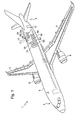
- Figure 1 illustrates an aircraft 1 provided with a fuselage 6, which has a front part 2 and a rear part 3, wings 4 each of which is attached to the fuselage 6 at a central part thereof, and two engines 5, each of those engines 5 being attached to a lower wall of a respective wing 4 and extending from the respective wing 4 parallel to the fuselage 6 towards the front part 2 of the aircraft 1.
- This aircraft 1 further comprises, in the rear part 3 of its fuselage 6, a main ventilation duct 10 and a dedicated ventilation duct 15 which is juxtaposed against the main ventilation duct 10.
- the aircraft 1 further comprises an integrated system 20 for cooling a fluid adapted to supply for example an air conditioning system of the aircraft 1 and/or adapted to cool electrical consumers.
- This integrated cooling system 20 is partially disposed in the main ventilation duct 10.
- the aircraft 1 further comprises a heat exchanger 25 situated in the vicinity of the integrated cooling system 20 and which is adapted to cool the fluid passing in that cooling system 20 by virtue of the circulation of that fluid through the heat exchanger 25.
- the heat exchanger 25 is disposed within the main ventilation duct 10.
- the aircraft 1 further comprises a reversible rotary electrical machine 30 situated in the vicinity of the heat exchanger 25 and disposed within the main ventilation duct 10.
- This reversible rotary electrical machine 30 comprises a rotor (not shown) able to turn about a longitudinal axis so as to drive an output shaft 34 ( Figures 4 to 9 ), and a stator (not shown) mounted around the rotor.
- the longitudinal axis constitutes the output shaft and the rotational axis of the rotor of the reversible rotary electrical machine 30.
- the aircraft 1 further comprises a wheel 35 for imparting movement to a stream of air, which is mounted on the output shaft 34 of the reversible rotary electrical machine 30, externally thereof.
- the wheel 35 has a set of blades whose free end substantially follows the profile of the inner surface of the main ventilation duct 10.
- the wheel 35 is thus here disposed within that main ventilation duct 10.
- the assembly formed by the reversible rotary electrical machine 30 and the wheel 35 for imparting movement to a stream of air forms a fan adapted to send cold air (by extraction or blowing) in the direction of the heat exchanger 25 in order to cool it.
- the reversible rotary electrical machine 30 which is electrically supplied and which drives the wheel 35 to impart movement to a stream of air.
- the reversible rotary electrical machine 30 is capable of being rotationally driven by that wheel 35, itself driven by a stream of air passing in the dedicated ventilation duct 25, to produce electrical energy (alternator mode).
- the aircraft 1 further comprises an electricity distribution network 70 connected to the reversible rotary electrical machine 30.
- the aircraft 1 also comprises a checking unit 60, a control circuit 50 as well as a reversible power converter 40.
- the reversible power converter 40 is connected to the rotary electrical machine 30, to the control circuit 50 and to the electricity distribution network 70.
- the control circuit 50 is furthermore connected to the checking unit 60.
- This checking unit 60 is furthermore connected to the electricity distribution network 70.
- the aircraft 1 further comprises energy storage modules 65 connected to the checking unit 60 and also connected to the electricity distribution network 70.
- These energy storage modules 65 comprise for example a supply battery (of Nickel-Cadmium type), and/or a plurality of capacitive cells for forming at least one supercapacitor, or even several of them in parallel.
- the dedicated ventilation duct 15 has a device for regulating the rate of flow of air entering that duct 15.
- the aircraft 1 further comprises a control module 55 adapted to control the regulating device 17 of the duct 15.
- This control module 55 is connected to the checking unit 60.
- the checking unit 60 here forms a part of a main checking unit of the aircraft 1.
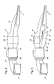
- Figure 2 illustrates the main ventilation duct 10 in isolation with, inside it, the heat exchanger 25, the reversible rotary electrical machine 30 and the wheel (not visible in that Figure).
- This main ventilation duct 10 comprises an air inlet 11 and an air outlet 12 which are formed in the fuselage 6 of the aircraft 1, that air inlet 11 being directed towards the lower part 2 and the air outlet 12 being directed towards the rear part 3.
- This air inlet 11 of the main ventilation duct 10 has a curved form which diverges towards the inside of that main duct 10, well-know under the name NACA type air inlet.
- This main ventilation duct 10 has a first section 13 extending from the air inlet 11, that first section having a flared shape up to a second section 14 which is widened relative to the first section 13.
- This main ventilation duct 10 furthermore has a third section 18 which is narrowed relative to the second section 14, the reversible rotary electrical machine 30 and the wheel 35 being disposed in that third section 18.
- the main ventilation duct 10 has a fourth section 19 extending from the third section 18 to the air outlet 12, this fourth section again being narrowed relative to the third section and moreover being bent.
- FIG. 3 illustrates this same main ventilation duct 10 with in addition the dedicated ventilation duct 15 juxtaposed against the main ventilation duct 10.
- This dedicated ventilation duct 15 has an air inlet 16 and an air outlet (which is not shown) which discharges directly into the main ventilation duct 10 at the junction between the second section 14 and the third section 18, in other words at the location of the wheel 35 joined to the shaft 34 of the reversible rotary electrical machine 30.
- the dedicated ventilation duct 15 has a first wall 22 which is flat and disposed facing the first and second sections 13 and 14 of the main ventilation duct 10, that first wall 22 extending between the air inlet 16 and the air outlet (not shown) of that dedicated ventilation duct 15.
- the dedicated ventilation duct 15 furthermore has a second wall 21 which curves away from the first wall 22 and extends between the air inlet 16 and the air outlet (not shown) of the dedicated duct 15.
- the dedicated ventilation duct 15 furthermore has a third wall 23 and a fourth wall 24 facing each other and connecting the first wall 22 and the second wall 21, its third and fourth walls 23, 24 being flat.
- the dedicated ventilation duct 15 further comprises, at the location of its air inlet16, a movable door 17.
- This movable door 17 is connected to one end of the second wall 21 at the location of the air inlet 16, and to the flat third and fourth walls 23, 24.
- the door 17 is movable so as to regulate the rate of flow of the stream of air entering through that air inlet 16.
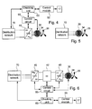
- Figure 4 diagrammatically and partially illustrates a first example embodiment of the electrical circuit of the aircraft 1.
- the reversible rotary electrical machine 30 is mechanically linked to the wheel 35 by the shaft 34.
- the reversible rotary electrical machine 30 is of three-phase type, each of its phases being electrically connected to the reversible power converter 40.
- This reversible converter 40 is capable of operating as a rectifier, that is to say to convert electrical energy of alternating type into electrical energy of direct type (AC/DC), and as an inverter, that is to say to transform electrical energy of direct type into electrical energy of alternating type (DC/AC).
- this reversible converter 40 is electrically connected to the electricity distribution network 70 of the aircraft 1.
- the electricity distribution network 70 is electrically connected to the checking unit 60, which is furthermore electrically connected to the control module 55 which is adapted to control the movable door 17 of the dedicated ventilation duct 15.
- the checking unit 60 and the converter 40 are both electrically connected to the control circuit 50.
- the control circuit 50 is furthermore electrically connected to the reversible rotary electrical machine 30.
- the checking unit 60 sends and receives information to and from the distribution network 70, the control module 55 of the control circuit 50, and also the main checking unit (not shown) of the aircraft 1.
- the control module 55 sends and receives information to and from the checking unit 60, and sends the information to the movable door 17 for its movement in order to regulate the rate of flow of the air entering by the air inlet 16 of the dedicated ventilation duct 15.
- the control circuit 50 receives and sends information respectively to and from the checking unit 60, the reversible converter 40 and the reversible rotary electrical machine 30.
- the reversible converter 40 is adapted to electrically transfer energy, through conversion, between the reversible rotary electrical machine 30 and the distribution network 70.
- the reversible rotary electrical machine 30, as previously indicated, is adapted to be supplied by the electricity distribution network 70 via the reversible converter 40 to rotationally drive its shaft 34 and thereby rotationally drive the wheel 35.
- the reversible rotary electrical machine 30 operates in motor mode.
- This reversible rotary electrical machine 30 is furthermore adapted to be driven by its shaft 34, which is first driven by the wheel 35.
- the reversible rotary electrical machine 30 operates in alternator mode, that is to say that it generates alternating current electrical energy on those three phases which is converted into direct current electrical energy by the reversible converter 40 then transferred to the electricity distribution network 70, which conveys it to the consumers and/or to the energy storage module 65.
- the control module is adapted to control the reversible power converter 40 depending on the mode of operation imposed on the reversible rotary electrical machine 30.
- the control circuit 50 receives commands from the checking unit 60.
- the control module 55 itself is adapted to control the movement of the movable door 17.
- the control module 55 receives commands from the checking unit 60.
- an air stream enters the main ventilation duct 10 via the air inlet 11, which air stream enables the heat exchanger 25 to be cooled directly.
- the reversible rotary electrical machine 30 operates in its alternator mode, with the movable door 17 being moved to create a stream of air having a sufficient rate of flow entering by the air inlet 16 and passing through the dedicated ventilation duct 15 to the air outlet (not shown), to finally supply the wheel 35 to make it turn.
- the wheel 35 drives the reversible rotary electrical machine 30 mechanically which generates additional electrical energy provided to the electricity distribution network 70.
- the door 17 is operated by the control module 55 so as to adapt, or even maximize, the rate of air flow when the reversible rotary electrical machine 30 operates in alternator mode, and to minimize it, or even eliminate it, when the reversible rotary electrical machine 30 operates in motor mode.
- the checking unit 60 sends commands to the control module 55 which transforms them into data for moving the movable door 17.
- the power generated by the reversible rotary electrical machine 30 is directly adjustable by control of that machine 30, where the door 17 has two modes, referred to as all or nothing, that is to say if it is open or closed.
- an emergency operating mode it is also necessary to make the reversible rotary electrical machine 30 operate in its alternator operating mode.
- the heat exchanger 25 When the aircraft is in a low altitude flight phase, in other words at an altitude not making it possible to have a stream of air flowing in the main ventilation duct 70 with a sufficient rate of flow to cool the heat exchanger 25 through which that air passes, and when the aircraft 1 is in take-off or landing phase, the heat exchanger 25 must furthermore be cooled by virtue of the fan formed by the wheel 35 associated with the reversible rotary electrical machine 30, which operates in motor mode.
- the reversible rotary electrical machine 30 rotationally drives the wheel 35 which imparts movement to a stream of air within the main ventilation duct 10, which stream is directed towards the heat exchanger 25 for it to be cooled.
- This reversible rotary electrical machine 30 operates as an alternator and is thus considered as a source of electrical energy. However, within the aircraft 1, there are generally other sources of electrical energy operating simultaneously (main and/or emergency energy sources)
- checking unit 60 is adapted to supervise all the energy sources of the aircraft 1 when they operate simultaneously, which checking unit 60 would where appropriate check the level of voltage on the electricity distribution network 70.
- the control circuit 50 is adapted to perform current control of the reversible converter 40 operating as a rectifier via a control loop making it possible to control the torque of the shaft 34 of the reversible rotary electrical machine 30 (or of the rotor, or of the wheel 35), or the speed of the shaft 34 or directly to control the power delivered by the reversible rotary electrical machine 30.
- control circuit 50 When no main energy source other than the reversible rotary electrical machine 30 operating in alternator mode checks the amplitude of the voltage on the electricity distribution network 70, the control circuit 50 is then adapted to control the amplitude of the voltage delivered by the reversible converter 40 operating as a rectifier on the electricity distribution network 70, via an external control loop.
- Figure 5 illustrates a second diagrammatic example of a circuit of the aircraft 1.
- the reversible rotary electrical machine 30 is directly connected to the electricity distribution network 70, which is adapted to transport alternating current electrical energy.
- the reversible rotary electrical machine 30 acts as a source of current directly connected to the network 70.
- Figure 6 illustrates a third diagrammatic example of a circuit of the aircraft 1.
- the power stage formed by the reversible converter 40 in Figure 4 is now formed by two reversible converters 40 and 45 as well as an electrical energy coupling device forming a reversible converter of d.c./d.c. type.
- the reversible rotary electrical machine 30 is now connected to the first reversible converter 40, which is electrically connected to device 42.
- the electricity distribution network 70 is now connected to the second reversible converter 45, which is furthermore electrically connected to the device 42.
- the reversible power converters 40 and 45 are capable of operating as rectifiers and as inverters.
- the device 42 comprises a filter, of low-pass type, and enables the transfer to be made between the direct current electrical energy delivered by the respective reversible converter 40, 45 and supplied to the respective reversible converter 45, 40.
- control circuit 50 is electrically connected to each of the converters 40 and 45 and to the device 42.
- the control circuit 50 is adapted to control at the same time the reversible converter 40, the reversible converter 45 and the device 42.
- the power stage which converts the alternating current electrical energy supplied by the reversible rotary electrical machine 30 into alternating current electrical energy delivered by the reversible converter 45 in the distribution network 70 is regulated in power, in torque or in speed.
- control circuit 50 is adapted to perform current control of the reversible converter 40 operating as a rectifier via a simple control loop so as to control the power delivered (that is to say the torque or the speed of the shaft 34, or directly the power delivered by the machine 30).
- the control circuit 50 is furthermore adapted to perform voltage control of the device 45 via an external control loop.
- the control circuit 50 is also adapted to perform current control of the reversible converter 45 operating as an inverter via an internal control loop.
- control circuit 50 is adapted to control the reversible converter 40 and the device 42 in the same way as above.
- the control circuit 50 is furthermore adapted to perform current control of the reversible converter 45 operating as an inverter via an internal control loop and the control circuit 50 is adapted to control the amplitude and the frequency of the alternating voltage delivered by that reversible converter 45 via an external control loop.
- Figure 7 illustrates a fourth example embodiment of the electrical circuit of aircraft 1, in which an energy storage module 65 is electrically connected in parallel between the electricity distribution network 70 and the reversible converter 40.
- This energy storage module 65 comprises a battery, with furthermore one or more supercapacitors.
- the reversible converter 40 delivers direct current electrical energy directly to the electricity distribution network 70.
- the management of the electrical energy generated by the reversible rotary electrical machine 30 and by the energy storage module 65 in parallel depends on the power absorbed by the electricity distribution network 70.
- This quantity of absorbed power may be measured directly on the network 70 by virtue of a voltage measurement, and/or by other measurements of current which may facilitate the management of energy.
- the energy storage module 65 acts as a source of voltage when the power absorbed on the network 70 is greater than the maximum power which can be supplied by the reversible rotary electrical machine 30, two energy management strategies are possible depending on the quantity of power really absorbed.
- the power really absorbed on the network 70 is less than the maximum power that the reversible rotary electrical machine 30 can generate, that machine 30 alone generates the electrical energy required by the network 70, without assistance from the energy storage module 65.
- the reversible rotary electrical machine 30 and the converter 40 thus act together as a voltage source.
- control circuit 50 is adapted to perform current control of the reversible converter 40 acting as a rectifier via an internal control loop so as to control the torque on the shaft 34, and the control circuit 50 is furthermore adapted to control the amplitude of the voltage delivered by the reversible converter 40 to the network 70 via an external control loop.
- the machine 30 If the power really absorbed by the network 70 is greater than the maximum power which the reversible rotary electrical machine 30 can generate, the machine 30 generates its maximum power and the energy storage module 65 supplies the rest of the power required to attain the power really absorbed by the network 70.
- the reversible rotary electrical machine 30 acts as a current source, and the control circuit 50 is adapted to perform current control of the reversible converter 40 via a single control loop.
- This regulation in fact corresponds to regulating the machine 30 to its maximum power value.
- the energy storage module 65 furthermore acts as a voltage source.
- checking unit 60 is adapted to control the amplitude of the voltage supplied to the distribution network 70 via a control loop, and checking unit 60 is optionally adapted to check the quantity of current entering and leaving the energy storage module 65 so as to monitor its state of charge.
- the energy storage module 65 it is also possible for the energy storage module 65 to continuously act as a voltage source, and two strategies may then be envisaged depending on the power really absorbed on the distribution network.
- the energy storage module 65 then acts as a component through which the power delivered by that machine 30 transits.
- the checking unit 60 is adapted to check the amplitude of the voltage at the terminals of the energy storage module 65, which voltage is delivered to electricity distribution network 70.
- the checking unit 60 is furthermore adapted to check the quantity of current entering and leaving the terminals of the energy storage module 65 so as to check its state of charge.
- the energy storage module 65 supplies, in addition to the power generated by the machine 30, the rest of the power required on the distribution network 70.
- the checking unit 60 is adapted to check the amplitude of the voltage delivered by the energy storage module 65 to the electricity distribution network 70, and, optionally, to check the quantity of current entering and leaving the terminals of the energy storage module 65 so as to check its state of charge.
- Figure 8 illustrates a fifth example embodiment of the electrical circuit of the aircraft 1.
- the circuit illustrated in Figure 9 comprises an additional reversible rotary electrical machine 30 associated with an additional wheel 35 via an additional shaft 34.
- additional rotary electrical machine 30 is electrically connected to an additional reversible converter 40, which is electrically connected in parallel between the electricity distribution network 70 and the reversible converter 40.
- the control circuit 50 is then electrically connected to both reversible converters 40.
- the control circuit receives and sends information from and to each of the reversible converters 40.
- the operation in parallel of the first and second reversible rotary electrical machines 30 depends on the quantity of power really absorbed by the electricity distribution network 70.
- the reference reversible rotary electrical machine 30 thus acts as a source of voltage.
- control circuit 50 is adapted to provide current control of the reversible converter 40 associated with that reference machine 30 so as to control the torque or the speed of the shaft 34 of that machine 30, or its power.
- control circuit 50 is adapted to control the amplitude of the voltage delivered by that reversible converter 40 associated with the reference reversible rotary electrical machine 30 via an external control loop.
- the latter supplies its maximum power and the rest of the power required is supplied by the other reversible rotary electrical machine 30.
- the reference reversible rotary electrical machine 30 thus acts as a source of current, and where appropriate, the control circuit 50 is adapted to provide current control of the reversible converter 40 associated with the reference machine 30, via a single control loop which in fact enables that reference machine 30 to be set to its maximum power value.
- the other reversible rotary electrical machine 30 thus acts as a source of voltage and where appropriate, the control circuit 50 is adapted to provide current control of the reversible converter 40 associated with that other machine 30 via an internal control loop, so as to control the torque on its shaft 34.
- control circuit 50 is adapted to control the amplitude of the voltage delivered to the network 70 by the reversible converter 40 associated with the other machine 30, via an external control loop.
- the aircraft comprises other dedicated ventilation ducts of the same type as that which has just been described, which are each juxtaposed or not juxtaposed against a respective main ventilation duct, those dedicated ventilation ducts being dedicated to the supply air of the reversible rotary electrical machine.
- those other dedicated ducts and/or main ducts are installed in the ventral fairing of the aircraft, in the vicinity of the wings, fore or aft of the latter, or those other ducts are installed in the region of the front undercarriage of the aircraft.
- the main ventilation duct and the dedicated ventilation duct are merged.
- the main duct includes or does not include a regulating device as described for the dedicated duct 15, that regulating device being controlled or not controlled by a control module as described above.
- the electrical energy coupling device of d.c./d.c. type comprises, in addition to a filter, a surge limiter and/or a power dissipation unit.
- the electrical energy coupling device comprises an energy storage system connected via a static converter, or uniquely comprises a block of capacitors. In all cases, this device is a filtering component contributing to putting into form the electrical energy processed by the reversible converter 40, and optionally by the reversible converter 45.
- the reversible rotary electrical machine associated with the wheel when the reversible rotary electrical machine associated with the wheel operates as a fan, it enables for example a non-pressurized zone to be ventilated to avoid the accumulation of fuel vapor.
- control module enabling the regulating device present in the dedicated duct to be acted upon is integrated into the checking unit, and/or the control circuit enabling the reversible power converter to be controlled is integrated into the checking unit.
- the aircraft comprises an electrical energy control system dedicated to the emergency operation of the aircraft, which, when that emergency operation is triggered, takes control of the checking unit, of the control circuit, as well as of the control module, in order to make available all the functionalities required for implementing that operation.
- the air inlet 16 of duct 15 is closed, and where appropriate, either the machine 30 is controlled to generate a power residue with the air supplied by duct 10, or the machine 30 is controlled so as not to supply power, or the wheel 35 is mechanically locked.
- the geometry of the rotary electrical machine 30 and/or the wheel 35 and/or duct 10 and/or duct 15 may be modified to improve the aerodynamic performance.
Landscapes
- Engineering & Computer Science (AREA)
- Aviation & Aerospace Engineering (AREA)
- Health & Medical Sciences (AREA)
- General Health & Medical Sciences (AREA)
- Pulmonology (AREA)
- Motor Or Generator Cooling System (AREA)
- Control Of Multiple Motors (AREA)
- Control Of Electric Motors In General (AREA)
Applications Claiming Priority (1)
| Application Number | Priority Date | Filing Date | Title |
|---|---|---|---|
| US12/967,765 US9162773B2 (en) | 2010-12-14 | 2010-12-14 | Aircraft comprising a reversible rotary electrical machine |
Publications (3)
| Publication Number | Publication Date |
|---|---|
| EP2465775A2 true EP2465775A2 (fr) | 2012-06-20 |
| EP2465775A3 EP2465775A3 (fr) | 2017-06-28 |
| EP2465775B1 EP2465775B1 (fr) | 2018-10-10 |
Family
ID=45047623
Family Applications (1)
| Application Number | Title | Priority Date | Filing Date |
|---|---|---|---|
| EP11190380.3A Active EP2465775B1 (fr) | 2010-12-14 | 2011-11-23 | Avion comprenant une machine électrique rotative réversible |
Country Status (4)
| Country | Link |
|---|---|
| US (1) | US9162773B2 (fr) |
| EP (1) | EP2465775B1 (fr) |
| CN (1) | CN102556353B (fr) |
| CA (1) | CA2758211C (fr) |
Cited By (3)
| Publication number | Priority date | Publication date | Assignee | Title |
|---|---|---|---|---|
| WO2020191131A1 (fr) * | 2019-03-19 | 2020-09-24 | Mag Aerospace Industries, Llc | Utilisation d'un générateur de vide de système de déchets d'aéronef pour fournir de l'énergie électrique |
| WO2021064390A3 (fr) * | 2019-10-02 | 2021-07-15 | Electric Aviation Group Ltd | Systèmes et procédés associés à un aéronef |
| GB2593416A (en) * | 2019-10-02 | 2021-09-29 | Advanced Mobility Res And Development Ltd | Systems and methods for aircraft |
Families Citing this family (4)
| Publication number | Priority date | Publication date | Assignee | Title |
|---|---|---|---|---|
| US9254924B2 (en) * | 2011-08-12 | 2016-02-09 | Hamilton Sundstrand Corporation | Pressure influencing assembly for an aircraft auxiliary system |
| DE102016123254A1 (de) * | 2015-12-23 | 2017-06-29 | Christian Schmid | Drehflügel-Fluggerät sowie eine Start- und Landevorrichtung für ein solches Drehflügel-Fluggerät |
| CN109763897B (zh) * | 2019-01-15 | 2021-04-20 | 三亚哈尔滨工程大学南海创新发展基地 | 一种基于金属纳米粉末燃烧的飞行器辅助发电机构 |
| FR3093080B1 (fr) * | 2019-02-26 | 2021-03-05 | Safran Helicopter Engines | Architecture propulsive hybride-electrique et procédé de dissipation d’énergie électrique dans une telle architecture |
Family Cites Families (9)
| Publication number | Priority date | Publication date | Assignee | Title |
|---|---|---|---|---|
| US5709103A (en) * | 1996-08-15 | 1998-01-20 | Mcdonnell Douglas Coporation | Electrically powered differential air-cycle air conditioning machine |
| US6735953B1 (en) * | 1997-12-22 | 2004-05-18 | Allied Signal Inc. | Turbomachine-driven environmental control system |
| US6189324B1 (en) * | 1999-10-05 | 2001-02-20 | Samuel B. Williams | Environment control unit for turbine engine |
| US7210653B2 (en) * | 2002-10-22 | 2007-05-01 | The Boeing Company | Electric-based secondary power system architectures for aircraft |
| US6776002B1 (en) * | 2003-04-25 | 2004-08-17 | Northrop Grumman Corporation | Magnetically coupled integrated power and cooling unit |
| US7578136B2 (en) * | 2004-08-23 | 2009-08-25 | Honeywell International Inc. | Integrated power and pressurization system |
| JP4501812B2 (ja) * | 2005-08-09 | 2010-07-14 | トヨタ自動車株式会社 | 最大出力設定装置およびこれを備える駆動装置並びにこれを備える動力出力装置、これを搭載する自動車、最大出力設定方法 |
| FR2902705B1 (fr) * | 2006-06-27 | 2009-04-10 | Valeo Equip Electr Moteur | Systeme micro-hybride pour vehicule automobile incorporant un module de strategies de pilotage |
| GB0909158D0 (en) * | 2009-05-29 | 2009-07-08 | Rolls Royce Plc | An aircraft having a lift/propulsion unit |
-
2010
- 2010-12-14 US US12/967,765 patent/US9162773B2/en active Active
-
2011
- 2011-11-07 CA CA2758211A patent/CA2758211C/fr not_active Expired - Fee Related
- 2011-11-23 EP EP11190380.3A patent/EP2465775B1/fr active Active
- 2011-12-13 CN CN201110412921.5A patent/CN102556353B/zh not_active Expired - Fee Related
Non-Patent Citations (1)
| Title |
|---|
| None |
Cited By (3)
| Publication number | Priority date | Publication date | Assignee | Title |
|---|---|---|---|---|
| WO2020191131A1 (fr) * | 2019-03-19 | 2020-09-24 | Mag Aerospace Industries, Llc | Utilisation d'un générateur de vide de système de déchets d'aéronef pour fournir de l'énergie électrique |
| WO2021064390A3 (fr) * | 2019-10-02 | 2021-07-15 | Electric Aviation Group Ltd | Systèmes et procédés associés à un aéronef |
| GB2593416A (en) * | 2019-10-02 | 2021-09-29 | Advanced Mobility Res And Development Ltd | Systems and methods for aircraft |
Also Published As
| Publication number | Publication date |
|---|---|
| US9162773B2 (en) | 2015-10-20 |
| US20120146403A1 (en) | 2012-06-14 |
| CA2758211C (fr) | 2019-01-15 |
| CA2758211A1 (fr) | 2012-06-14 |
| EP2465775B1 (fr) | 2018-10-10 |
| CN102556353A (zh) | 2012-07-11 |
| CN102556353B (zh) | 2016-08-03 |
| EP2465775A3 (fr) | 2017-06-28 |
Similar Documents
| Publication | Publication Date | Title |
|---|---|---|
| EP2465775B1 (fr) | Avion comprenant une machine électrique rotative réversible | |
| US20250353602A1 (en) | Propulsion system and methods of use thereof | |
| US8662445B2 (en) | Hybrid power system architecture for an aircraft | |
| US10906657B2 (en) | Aircraft system with distributed propulsion | |
| US10759545B2 (en) | Hybrid electric aircraft system with distributed propulsion | |
| US20200017225A1 (en) | Hybrid electric aircraft | |
| US9815564B2 (en) | Non-propulsive utility power (NPUP) generation system for providing full-time secondary power during operation of an aircraft | |
| US7687927B2 (en) | Electrical systems architecture for an aircraft, and related operating methods | |
| US8218341B2 (en) | Integrated aircraft power conditioning unit | |
| CN108528735B (zh) | 串联式混合动力飞机及其控制方法 | |
| US20210039794A1 (en) | Cabin outflow air energy optimized cabin pressurizing system | |
| EP3895993B1 (fr) | Schéma de charge pour systèmes de propulsion électrique | |
| US12240615B2 (en) | Electric propulsor with electric machine in thermal communication with a heat exchanger | |
| US12071250B2 (en) | Electric architecture for hybrid propulsion | |
| CN109689504A (zh) | 用于起动和检修飞机喷气式发动机的地面起动装置 | |
| Steiner et al. | Performance and sizing of transport aircraft employing electrically-powered distributed propulsion | |
| US12595071B1 (en) | Parallel hybrid electric vertical takeoff and landing aircraft | |
| CN223934966U (zh) | 飞行器电力推进系统及机翼分布式电动螺旋桨推进飞行器 | |
| RU2778469C1 (ru) | Электрическая архитектура гибридной силовой установки | |
| Barraco et al. | Flatness based control of an HVDC bus powered by a turboshaft with multiple generators and optimization of power sharing | |
| CN119929164A (zh) | 飞行器电力推进系统及机翼分布式电动螺旋桨推进飞行器 | |
| BR112021006414B1 (pt) | Aeronave com propulsão térmica/elétrica híbrida | |
| ROBOAM et al. | Toward Optimized Electrical Networks Embedded in More-Electrical Aircraft | |
| Vratny et al. | DESIGN AND OFF-DESIGN PERFORMANCE OF ELECTRIC SYSTEM ARCHITECTURES FOR ELECTRIC POWERED AIRCRAFT |
Legal Events
| Date | Code | Title | Description |
|---|---|---|---|
| PUAI | Public reference made under article 153(3) epc to a published international application that has entered the european phase |
Free format text: ORIGINAL CODE: 0009012 |
|
| AK | Designated contracting states |
Kind code of ref document: A2 Designated state(s): AL AT BE BG CH CY CZ DE DK EE ES FI FR GB GR HR HU IE IS IT LI LT LU LV MC MK MT NL NO PL PT RO RS SE SI SK SM TR |
|
| AX | Request for extension of the european patent |
Extension state: BA ME |
|
| RIN1 | Information on inventor provided before grant (corrected) |
Inventor name: MAVIER, JEROME Inventor name: BARKOWSKY, JAN Inventor name: LANDO, JEAN-LOUIS Inventor name: FOCH, ETIENNE Inventor name: ROBOAM, XAVIER |
|
| PUAL | Search report despatched |
Free format text: ORIGINAL CODE: 0009013 |
|
| AK | Designated contracting states |
Kind code of ref document: A3 Designated state(s): AL AT BE BG CH CY CZ DE DK EE ES FI FR GB GR HR HU IE IS IT LI LT LU LV MC MK MT NL NO PL PT RO RS SE SI SK SM TR |
|
| AX | Request for extension of the european patent |
Extension state: BA ME |
|
| RIC1 | Information provided on ipc code assigned before grant |
Ipc: B64D 41/00 20060101AFI20170519BHEP Ipc: B64D 13/06 20060101ALN20170519BHEP |
|
| STAA | Information on the status of an ep patent application or granted ep patent |
Free format text: STATUS: REQUEST FOR EXAMINATION WAS MADE |
|
| 17P | Request for examination filed |
Effective date: 20171129 |
|
| RBV | Designated contracting states (corrected) |
Designated state(s): AL AT BE BG CH CY CZ DE DK EE ES FI FR GB GR HR HU IE IS IT LI LT LU LV MC MK MT NL NO PL PT RO RS SE SI SK SM TR |
|
| RIC1 | Information provided on ipc code assigned before grant |
Ipc: B64D 13/06 20060101ALN20180531BHEP Ipc: B64D 41/00 20060101AFI20180531BHEP |
|
| GRAP | Despatch of communication of intention to grant a patent |
Free format text: ORIGINAL CODE: EPIDOSNIGR1 |
|
| STAA | Information on the status of an ep patent application or granted ep patent |
Free format text: STATUS: GRANT OF PATENT IS INTENDED |
|
| INTG | Intention to grant announced |
Effective date: 20180717 |
|
| GRAS | Grant fee paid |
Free format text: ORIGINAL CODE: EPIDOSNIGR3 |
|
| GRAA | (expected) grant |
Free format text: ORIGINAL CODE: 0009210 |
|
| STAA | Information on the status of an ep patent application or granted ep patent |
Free format text: STATUS: THE PATENT HAS BEEN GRANTED |
|
| AK | Designated contracting states |
Kind code of ref document: B1 Designated state(s): AL AT BE BG CH CY CZ DE DK EE ES FI FR GB GR HR HU IE IS IT LI LT LU LV MC MK MT NL NO PL PT RO RS SE SI SK SM TR |
|
| REG | Reference to a national code |
Ref country code: GB Ref legal event code: FG4D |
|
| REG | Reference to a national code |
Ref country code: CH Ref legal event code: EP Ref country code: AT Ref legal event code: REF Ref document number: 1050931 Country of ref document: AT Kind code of ref document: T Effective date: 20181015 |
|
| REG | Reference to a national code |
Ref country code: IE Ref legal event code: FG4D |
|
| REG | Reference to a national code |
Ref country code: DE Ref legal event code: R096 Ref document number: 602011052730 Country of ref document: DE |
|
| REG | Reference to a national code |
Ref country code: NL Ref legal event code: MP Effective date: 20181010 |
|
| REG | Reference to a national code |
Ref country code: LT Ref legal event code: MG4D |
|
| REG | Reference to a national code |
Ref country code: AT Ref legal event code: MK05 Ref document number: 1050931 Country of ref document: AT Kind code of ref document: T Effective date: 20181010 |
|
| PG25 | Lapsed in a contracting state [announced via postgrant information from national office to epo] |
Ref country code: NL Free format text: LAPSE BECAUSE OF FAILURE TO SUBMIT A TRANSLATION OF THE DESCRIPTION OR TO PAY THE FEE WITHIN THE PRESCRIBED TIME-LIMIT Effective date: 20181010 |
|
| PG25 | Lapsed in a contracting state [announced via postgrant information from national office to epo] |
Ref country code: ES Free format text: LAPSE BECAUSE OF FAILURE TO SUBMIT A TRANSLATION OF THE DESCRIPTION OR TO PAY THE FEE WITHIN THE PRESCRIBED TIME-LIMIT Effective date: 20181010 Ref country code: AT Free format text: LAPSE BECAUSE OF FAILURE TO SUBMIT A TRANSLATION OF THE DESCRIPTION OR TO PAY THE FEE WITHIN THE PRESCRIBED TIME-LIMIT Effective date: 20181010 Ref country code: LT Free format text: LAPSE BECAUSE OF FAILURE TO SUBMIT A TRANSLATION OF THE DESCRIPTION OR TO PAY THE FEE WITHIN THE PRESCRIBED TIME-LIMIT Effective date: 20181010 Ref country code: NO Free format text: LAPSE BECAUSE OF FAILURE TO SUBMIT A TRANSLATION OF THE DESCRIPTION OR TO PAY THE FEE WITHIN THE PRESCRIBED TIME-LIMIT Effective date: 20190110 Ref country code: FI Free format text: LAPSE BECAUSE OF FAILURE TO SUBMIT A TRANSLATION OF THE DESCRIPTION OR TO PAY THE FEE WITHIN THE PRESCRIBED TIME-LIMIT Effective date: 20181010 Ref country code: IS Free format text: LAPSE BECAUSE OF FAILURE TO SUBMIT A TRANSLATION OF THE DESCRIPTION OR TO PAY THE FEE WITHIN THE PRESCRIBED TIME-LIMIT Effective date: 20190210 Ref country code: BG Free format text: LAPSE BECAUSE OF FAILURE TO SUBMIT A TRANSLATION OF THE DESCRIPTION OR TO PAY THE FEE WITHIN THE PRESCRIBED TIME-LIMIT Effective date: 20190110 Ref country code: PL Free format text: LAPSE BECAUSE OF FAILURE TO SUBMIT A TRANSLATION OF THE DESCRIPTION OR TO PAY THE FEE WITHIN THE PRESCRIBED TIME-LIMIT Effective date: 20181010 Ref country code: HR Free format text: LAPSE BECAUSE OF FAILURE TO SUBMIT A TRANSLATION OF THE DESCRIPTION OR TO PAY THE FEE WITHIN THE PRESCRIBED TIME-LIMIT Effective date: 20181010 Ref country code: LV Free format text: LAPSE BECAUSE OF FAILURE TO SUBMIT A TRANSLATION OF THE DESCRIPTION OR TO PAY THE FEE WITHIN THE PRESCRIBED TIME-LIMIT Effective date: 20181010 |
|
| PG25 | Lapsed in a contracting state [announced via postgrant information from national office to epo] |
Ref country code: GR Free format text: LAPSE BECAUSE OF FAILURE TO SUBMIT A TRANSLATION OF THE DESCRIPTION OR TO PAY THE FEE WITHIN THE PRESCRIBED TIME-LIMIT Effective date: 20190111 Ref country code: RS Free format text: LAPSE BECAUSE OF FAILURE TO SUBMIT A TRANSLATION OF THE DESCRIPTION OR TO PAY THE FEE WITHIN THE PRESCRIBED TIME-LIMIT Effective date: 20181010 Ref country code: SE Free format text: LAPSE BECAUSE OF FAILURE TO SUBMIT A TRANSLATION OF THE DESCRIPTION OR TO PAY THE FEE WITHIN THE PRESCRIBED TIME-LIMIT Effective date: 20181010 Ref country code: AL Free format text: LAPSE BECAUSE OF FAILURE TO SUBMIT A TRANSLATION OF THE DESCRIPTION OR TO PAY THE FEE WITHIN THE PRESCRIBED TIME-LIMIT Effective date: 20181010 Ref country code: PT Free format text: LAPSE BECAUSE OF FAILURE TO SUBMIT A TRANSLATION OF THE DESCRIPTION OR TO PAY THE FEE WITHIN THE PRESCRIBED TIME-LIMIT Effective date: 20190210 |
|
| REG | Reference to a national code |
Ref country code: CH Ref legal event code: PL |
|
| REG | Reference to a national code |
Ref country code: DE Ref legal event code: R097 Ref document number: 602011052730 Country of ref document: DE |
|
| PG25 | Lapsed in a contracting state [announced via postgrant information from national office to epo] |
Ref country code: LU Free format text: LAPSE BECAUSE OF NON-PAYMENT OF DUE FEES Effective date: 20181123 Ref country code: DK Free format text: LAPSE BECAUSE OF FAILURE TO SUBMIT A TRANSLATION OF THE DESCRIPTION OR TO PAY THE FEE WITHIN THE PRESCRIBED TIME-LIMIT Effective date: 20181010 Ref country code: IT Free format text: LAPSE BECAUSE OF FAILURE TO SUBMIT A TRANSLATION OF THE DESCRIPTION OR TO PAY THE FEE WITHIN THE PRESCRIBED TIME-LIMIT Effective date: 20181010 Ref country code: CZ Free format text: LAPSE BECAUSE OF FAILURE TO SUBMIT A TRANSLATION OF THE DESCRIPTION OR TO PAY THE FEE WITHIN THE PRESCRIBED TIME-LIMIT Effective date: 20181010 |
|
| PLBE | No opposition filed within time limit |
Free format text: ORIGINAL CODE: 0009261 |
|
| STAA | Information on the status of an ep patent application or granted ep patent |
Free format text: STATUS: NO OPPOSITION FILED WITHIN TIME LIMIT |
|
| REG | Reference to a national code |
Ref country code: BE Ref legal event code: MM Effective date: 20181130 |
|
| REG | Reference to a national code |
Ref country code: IE Ref legal event code: MM4A |
|
| PG25 | Lapsed in a contracting state [announced via postgrant information from national office to epo] |
Ref country code: RO Free format text: LAPSE BECAUSE OF FAILURE TO SUBMIT A TRANSLATION OF THE DESCRIPTION OR TO PAY THE FEE WITHIN THE PRESCRIBED TIME-LIMIT Effective date: 20181010 Ref country code: SK Free format text: LAPSE BECAUSE OF FAILURE TO SUBMIT A TRANSLATION OF THE DESCRIPTION OR TO PAY THE FEE WITHIN THE PRESCRIBED TIME-LIMIT Effective date: 20181010 Ref country code: CH Free format text: LAPSE BECAUSE OF NON-PAYMENT OF DUE FEES Effective date: 20181130 Ref country code: LI Free format text: LAPSE BECAUSE OF NON-PAYMENT OF DUE FEES Effective date: 20181130 Ref country code: MC Free format text: LAPSE BECAUSE OF FAILURE TO SUBMIT A TRANSLATION OF THE DESCRIPTION OR TO PAY THE FEE WITHIN THE PRESCRIBED TIME-LIMIT Effective date: 20181010 Ref country code: EE Free format text: LAPSE BECAUSE OF FAILURE TO SUBMIT A TRANSLATION OF THE DESCRIPTION OR TO PAY THE FEE WITHIN THE PRESCRIBED TIME-LIMIT Effective date: 20181010 Ref country code: SM Free format text: LAPSE BECAUSE OF FAILURE TO SUBMIT A TRANSLATION OF THE DESCRIPTION OR TO PAY THE FEE WITHIN THE PRESCRIBED TIME-LIMIT Effective date: 20181010 |
|
| 26N | No opposition filed |
Effective date: 20190711 |
|
| PG25 | Lapsed in a contracting state [announced via postgrant information from national office to epo] |
Ref country code: SI Free format text: LAPSE BECAUSE OF FAILURE TO SUBMIT A TRANSLATION OF THE DESCRIPTION OR TO PAY THE FEE WITHIN THE PRESCRIBED TIME-LIMIT Effective date: 20181010 Ref country code: IE Free format text: LAPSE BECAUSE OF NON-PAYMENT OF DUE FEES Effective date: 20181123 |
|
| PG25 | Lapsed in a contracting state [announced via postgrant information from national office to epo] |
Ref country code: BE Free format text: LAPSE BECAUSE OF NON-PAYMENT OF DUE FEES Effective date: 20181130 |
|
| PG25 | Lapsed in a contracting state [announced via postgrant information from national office to epo] |
Ref country code: MT Free format text: LAPSE BECAUSE OF NON-PAYMENT OF DUE FEES Effective date: 20181123 |
|
| PG25 | Lapsed in a contracting state [announced via postgrant information from national office to epo] |
Ref country code: TR Free format text: LAPSE BECAUSE OF FAILURE TO SUBMIT A TRANSLATION OF THE DESCRIPTION OR TO PAY THE FEE WITHIN THE PRESCRIBED TIME-LIMIT Effective date: 20181010 |
|
| PG25 | Lapsed in a contracting state [announced via postgrant information from national office to epo] |
Ref country code: HU Free format text: LAPSE BECAUSE OF FAILURE TO SUBMIT A TRANSLATION OF THE DESCRIPTION OR TO PAY THE FEE WITHIN THE PRESCRIBED TIME-LIMIT; INVALID AB INITIO Effective date: 20111123 Ref country code: MK Free format text: LAPSE BECAUSE OF NON-PAYMENT OF DUE FEES Effective date: 20181010 Ref country code: CY Free format text: LAPSE BECAUSE OF FAILURE TO SUBMIT A TRANSLATION OF THE DESCRIPTION OR TO PAY THE FEE WITHIN THE PRESCRIBED TIME-LIMIT Effective date: 20181010 |
|
| PGFP | Annual fee paid to national office [announced via postgrant information from national office to epo] |
Ref country code: DE Payment date: 20231121 Year of fee payment: 13 |
|
| REG | Reference to a national code |
Ref country code: DE Ref legal event code: R119 Ref document number: 602011052730 Country of ref document: DE |
|
| PG25 | Lapsed in a contracting state [announced via postgrant information from national office to epo] |
Ref country code: DE Free format text: LAPSE BECAUSE OF NON-PAYMENT OF DUE FEES Effective date: 20250603 |
|
| PGFP | Annual fee paid to national office [announced via postgrant information from national office to epo] |
Ref country code: GB Payment date: 20251121 Year of fee payment: 15 |
|
| PGFP | Annual fee paid to national office [announced via postgrant information from national office to epo] |
Ref country code: FR Payment date: 20251125 Year of fee payment: 15 |