EP2465914A2 - Chambre de trempe de gazéification et ensemble formant épurateur - Google Patents
Chambre de trempe de gazéification et ensemble formant épurateur Download PDFInfo
- Publication number
- EP2465914A2 EP2465914A2 EP11192781A EP11192781A EP2465914A2 EP 2465914 A2 EP2465914 A2 EP 2465914A2 EP 11192781 A EP11192781 A EP 11192781A EP 11192781 A EP11192781 A EP 11192781A EP 2465914 A2 EP2465914 A2 EP 2465914A2
- Authority
- EP
- European Patent Office
- Prior art keywords
- syngas
- quench chamber
- gasification
- chamber
- upper portion
- Prior art date
- Legal status (The legal status is an assumption and is not a legal conclusion. Google has not performed a legal analysis and makes no representation as to the accuracy of the status listed.)
- Granted
Links
- 238000010791 quenching Methods 0.000 title claims abstract description 145
- 238000002309 gasification Methods 0.000 title claims abstract description 78
- 239000002826 coolant Substances 0.000 claims abstract description 57
- 239000007788 liquid Substances 0.000 claims abstract description 56
- 238000001816 cooling Methods 0.000 claims abstract description 37
- 239000000203 mixture Substances 0.000 claims abstract description 14
- XLYOFNOQVPJJNP-UHFFFAOYSA-N water Substances O XLYOFNOQVPJJNP-UHFFFAOYSA-N 0.000 claims description 37
- 238000004891 communication Methods 0.000 claims description 7
- 230000003993 interaction Effects 0.000 claims description 5
- 239000012530 fluid Substances 0.000 claims description 4
- 238000013016 damping Methods 0.000 description 81
- 239000007789 gas Substances 0.000 description 33
- 239000012809 cooling fluid Substances 0.000 description 32
- 230000007246 mechanism Effects 0.000 description 24
- 238000002485 combustion reaction Methods 0.000 description 20
- 239000000446 fuel Substances 0.000 description 14
- 239000002893 slag Substances 0.000 description 8
- 229920006395 saturated elastomer Polymers 0.000 description 7
- IJGRMHOSHXDMSA-UHFFFAOYSA-N Atomic nitrogen Chemical compound N#N IJGRMHOSHXDMSA-UHFFFAOYSA-N 0.000 description 6
- CURLTUGMZLYLDI-UHFFFAOYSA-N Carbon dioxide Chemical compound O=C=O CURLTUGMZLYLDI-UHFFFAOYSA-N 0.000 description 6
- 238000000034 method Methods 0.000 description 6
- QVGXLLKOCUKJST-UHFFFAOYSA-N atomic oxygen Chemical compound [O] QVGXLLKOCUKJST-UHFFFAOYSA-N 0.000 description 5
- 230000008901 benefit Effects 0.000 description 5
- 239000000110 cooling liquid Substances 0.000 description 5
- 238000004519 manufacturing process Methods 0.000 description 5
- 230000000116 mitigating effect Effects 0.000 description 5
- 239000003245 coal Substances 0.000 description 4
- 239000000571 coke Substances 0.000 description 4
- 238000013461 design Methods 0.000 description 4
- 229910052760 oxygen Inorganic materials 0.000 description 4
- 239000001301 oxygen Substances 0.000 description 4
- 238000010248 power generation Methods 0.000 description 4
- 230000008569 process Effects 0.000 description 4
- 238000011084 recovery Methods 0.000 description 4
- 239000002002 slurry Substances 0.000 description 4
- NINIDFKCEFEMDL-UHFFFAOYSA-N Sulfur Chemical compound [S] NINIDFKCEFEMDL-UHFFFAOYSA-N 0.000 description 3
- 239000002253 acid Substances 0.000 description 3
- 239000001569 carbon dioxide Substances 0.000 description 3
- 229910002092 carbon dioxide Inorganic materials 0.000 description 3
- 229910052757 nitrogen Inorganic materials 0.000 description 3
- 239000007787 solid Substances 0.000 description 3
- 239000007921 spray Substances 0.000 description 3
- 229910052717 sulfur Inorganic materials 0.000 description 3
- 239000011593 sulfur Substances 0.000 description 3
- UGFAIRIUMAVXCW-UHFFFAOYSA-N Carbon monoxide Chemical compound [O+]#[C-] UGFAIRIUMAVXCW-UHFFFAOYSA-N 0.000 description 2
- 238000009825 accumulation Methods 0.000 description 2
- 229910002091 carbon monoxide Inorganic materials 0.000 description 2
- 238000011161 development Methods 0.000 description 2
- 230000007613 environmental effect Effects 0.000 description 2
- 238000012986 modification Methods 0.000 description 2
- 230000004048 modification Effects 0.000 description 2
- 230000010355 oscillation Effects 0.000 description 2
- 238000012545 processing Methods 0.000 description 2
- 230000009467 reduction Effects 0.000 description 2
- 230000000630 rising effect Effects 0.000 description 2
- 238000000926 separation method Methods 0.000 description 2
- 238000011144 upstream manufacturing Methods 0.000 description 2
- 238000003466 welding Methods 0.000 description 2
- OKTJSMMVPCPJKN-UHFFFAOYSA-N Carbon Chemical compound [C] OKTJSMMVPCPJKN-UHFFFAOYSA-N 0.000 description 1
- VEXZGXHMUGYJMC-UHFFFAOYSA-M Chloride anion Chemical compound [Cl-] VEXZGXHMUGYJMC-UHFFFAOYSA-M 0.000 description 1
- RWSOTUBLDIXVET-UHFFFAOYSA-N Dihydrogen sulfide Chemical compound S RWSOTUBLDIXVET-UHFFFAOYSA-N 0.000 description 1
- UFHFLCQGNIYNRP-UHFFFAOYSA-N Hydrogen Chemical compound [H][H] UFHFLCQGNIYNRP-UHFFFAOYSA-N 0.000 description 1
- 238000005273 aeration Methods 0.000 description 1
- 239000002956 ash Substances 0.000 description 1
- 229910052799 carbon Inorganic materials 0.000 description 1
- 238000006243 chemical reaction Methods 0.000 description 1
- 238000010586 diagram Methods 0.000 description 1
- 239000003085 diluting agent Substances 0.000 description 1
- 230000003292 diminished effect Effects 0.000 description 1
- 230000005611 electricity Effects 0.000 description 1
- 238000001704 evaporation Methods 0.000 description 1
- 230000008020 evaporation Effects 0.000 description 1
- 238000010438 heat treatment Methods 0.000 description 1
- 239000001257 hydrogen Substances 0.000 description 1
- 229910052739 hydrogen Inorganic materials 0.000 description 1
- 229910000037 hydrogen sulfide Inorganic materials 0.000 description 1
- 230000003116 impacting effect Effects 0.000 description 1
- 239000003077 lignite Substances 0.000 description 1
- 238000002360 preparation method Methods 0.000 description 1
- 238000000746 purification Methods 0.000 description 1
- 239000000376 reactant Substances 0.000 description 1
- 230000000717 retained effect Effects 0.000 description 1
- -1 steam Chemical compound 0.000 description 1
- 238000010408 sweeping Methods 0.000 description 1
- 238000012546 transfer Methods 0.000 description 1
Images


Classifications
-
- C—CHEMISTRY; METALLURGY
- C10—PETROLEUM, GAS OR COKE INDUSTRIES; TECHNICAL GASES CONTAINING CARBON MONOXIDE; FUELS; LUBRICANTS; PEAT
- C10J—PRODUCTION OF PRODUCER GAS, WATER-GAS, SYNTHESIS GAS FROM SOLID CARBONACEOUS MATERIAL, OR MIXTURES CONTAINING THESE GASES; CARBURETTING AIR OR OTHER GASES
- C10J3/00—Production of combustible gases containing carbon monoxide from solid carbonaceous fuels
- C10J3/72—Other features
- C10J3/82—Gas withdrawal means
- C10J3/84—Gas withdrawal means with means for removing dust or tar from the gas
-
- C—CHEMISTRY; METALLURGY
- C10—PETROLEUM, GAS OR COKE INDUSTRIES; TECHNICAL GASES CONTAINING CARBON MONOXIDE; FUELS; LUBRICANTS; PEAT
- C10J—PRODUCTION OF PRODUCER GAS, WATER-GAS, SYNTHESIS GAS FROM SOLID CARBONACEOUS MATERIAL, OR MIXTURES CONTAINING THESE GASES; CARBURETTING AIR OR OTHER GASES
- C10J3/00—Production of combustible gases containing carbon monoxide from solid carbonaceous fuels
- C10J3/46—Gasification of granular or pulverulent flues in suspension
- C10J3/48—Apparatus; Plants
- C10J3/485—Entrained flow gasifiers
-
- C—CHEMISTRY; METALLURGY
- C10—PETROLEUM, GAS OR COKE INDUSTRIES; TECHNICAL GASES CONTAINING CARBON MONOXIDE; FUELS; LUBRICANTS; PEAT
- C10J—PRODUCTION OF PRODUCER GAS, WATER-GAS, SYNTHESIS GAS FROM SOLID CARBONACEOUS MATERIAL, OR MIXTURES CONTAINING THESE GASES; CARBURETTING AIR OR OTHER GASES
- C10J3/00—Production of combustible gases containing carbon monoxide from solid carbonaceous fuels
- C10J3/72—Other features
- C10J3/74—Construction of shells or jackets
- C10J3/76—Water jackets; Steam boiler-jackets
-
- C—CHEMISTRY; METALLURGY
- C10—PETROLEUM, GAS OR COKE INDUSTRIES; TECHNICAL GASES CONTAINING CARBON MONOXIDE; FUELS; LUBRICANTS; PEAT
- C10J—PRODUCTION OF PRODUCER GAS, WATER-GAS, SYNTHESIS GAS FROM SOLID CARBONACEOUS MATERIAL, OR MIXTURES CONTAINING THESE GASES; CARBURETTING AIR OR OTHER GASES
- C10J3/00—Production of combustible gases containing carbon monoxide from solid carbonaceous fuels
- C10J3/72—Other features
- C10J3/82—Gas withdrawal means
- C10J3/84—Gas withdrawal means with means for removing dust or tar from the gas
- C10J3/845—Quench rings
-
- C—CHEMISTRY; METALLURGY
- C10—PETROLEUM, GAS OR COKE INDUSTRIES; TECHNICAL GASES CONTAINING CARBON MONOXIDE; FUELS; LUBRICANTS; PEAT
- C10K—PURIFYING OR MODIFYING THE CHEMICAL COMPOSITION OF COMBUSTIBLE GASES CONTAINING CARBON MONOXIDE
- C10K1/00—Purifying combustible gases containing carbon monoxide
- C10K1/08—Purifying combustible gases containing carbon monoxide by washing with liquids; Reviving the used wash liquors
-
- F—MECHANICAL ENGINEERING; LIGHTING; HEATING; WEAPONS; BLASTING
- F25—REFRIGERATION OR COOLING; COMBINED HEATING AND REFRIGERATION SYSTEMS; HEAT PUMP SYSTEMS; MANUFACTURE OR STORAGE OF ICE; LIQUEFACTION SOLIDIFICATION OF GASES
- F25J—LIQUEFACTION, SOLIDIFICATION OR SEPARATION OF GASES OR GASEOUS OR LIQUEFIED GASEOUS MIXTURES BY PRESSURE AND COLD TREATMENT OR BY BRINGING THEM INTO THE SUPERCRITICAL STATE
- F25J1/00—Processes or apparatus for liquefying or solidifying gases or gaseous mixtures
-
- C—CHEMISTRY; METALLURGY
- C10—PETROLEUM, GAS OR COKE INDUSTRIES; TECHNICAL GASES CONTAINING CARBON MONOXIDE; FUELS; LUBRICANTS; PEAT
- C10J—PRODUCTION OF PRODUCER GAS, WATER-GAS, SYNTHESIS GAS FROM SOLID CARBONACEOUS MATERIAL, OR MIXTURES CONTAINING THESE GASES; CARBURETTING AIR OR OTHER GASES
- C10J2300/00—Details of gasification processes
- C10J2300/09—Details of the feed, e.g. feeding of spent catalyst, inert gas or halogens
- C10J2300/0953—Gasifying agents
- C10J2300/0959—Oxygen
-
- C—CHEMISTRY; METALLURGY
- C10—PETROLEUM, GAS OR COKE INDUSTRIES; TECHNICAL GASES CONTAINING CARBON MONOXIDE; FUELS; LUBRICANTS; PEAT
- C10J—PRODUCTION OF PRODUCER GAS, WATER-GAS, SYNTHESIS GAS FROM SOLID CARBONACEOUS MATERIAL, OR MIXTURES CONTAINING THESE GASES; CARBURETTING AIR OR OTHER GASES
- C10J2300/00—Details of gasification processes
- C10J2300/09—Details of the feed, e.g. feeding of spent catalyst, inert gas or halogens
- C10J2300/0953—Gasifying agents
- C10J2300/0973—Water
- C10J2300/0976—Water as steam
-
- C—CHEMISTRY; METALLURGY
- C10—PETROLEUM, GAS OR COKE INDUSTRIES; TECHNICAL GASES CONTAINING CARBON MONOXIDE; FUELS; LUBRICANTS; PEAT
- C10J—PRODUCTION OF PRODUCER GAS, WATER-GAS, SYNTHESIS GAS FROM SOLID CARBONACEOUS MATERIAL, OR MIXTURES CONTAINING THESE GASES; CARBURETTING AIR OR OTHER GASES
- C10J2300/00—Details of gasification processes
- C10J2300/16—Integration of gasification processes with another plant or parts within the plant
- C10J2300/1671—Integration of gasification processes with another plant or parts within the plant with the production of electricity
-
- Y—GENERAL TAGGING OF NEW TECHNOLOGICAL DEVELOPMENTS; GENERAL TAGGING OF CROSS-SECTIONAL TECHNOLOGIES SPANNING OVER SEVERAL SECTIONS OF THE IPC; TECHNICAL SUBJECTS COVERED BY FORMER USPC CROSS-REFERENCE ART COLLECTIONS [XRACs] AND DIGESTS
- Y02—TECHNOLOGIES OR APPLICATIONS FOR MITIGATION OR ADAPTATION AGAINST CLIMATE CHANGE
- Y02E—REDUCTION OF GREENHOUSE GAS [GHG] EMISSIONS, RELATED TO ENERGY GENERATION, TRANSMISSION OR DISTRIBUTION
- Y02E20/00—Combustion technologies with mitigation potential
- Y02E20/16—Combined cycle power plant [CCPP], or combined cycle gas turbine [CCGT]
- Y02E20/18—Integrated gasification combined cycle [IGCC], e.g. combined with carbon capture and storage [CCS]
-
- Y—GENERAL TAGGING OF NEW TECHNOLOGICAL DEVELOPMENTS; GENERAL TAGGING OF CROSS-SECTIONAL TECHNOLOGIES SPANNING OVER SEVERAL SECTIONS OF THE IPC; TECHNICAL SUBJECTS COVERED BY FORMER USPC CROSS-REFERENCE ART COLLECTIONS [XRACs] AND DIGESTS
- Y02—TECHNOLOGIES OR APPLICATIONS FOR MITIGATION OR ADAPTATION AGAINST CLIMATE CHANGE
- Y02P—CLIMATE CHANGE MITIGATION TECHNOLOGIES IN THE PRODUCTION OR PROCESSING OF GOODS
- Y02P20/00—Technologies relating to chemical industry
- Y02P20/10—Process efficiency
- Y02P20/129—Energy recovery, e.g. by cogeneration, H2recovery or pressure recovery turbines
Definitions
- the invention relates generally to gasifiers, and more particularly to a gasification quench chamber and scrubber assembly.
- a particulated carbonaceous fuel such as coal or coke or a carbonaceous gas
- the process is carried out at relatively hot temperatures and high pressures in a combustion chamber.
- a gasification quench chamber or quench chamber, disposed downstream of the combustion chamber.
- the quench chamber contains a liquid coolant such as water. The effluent from the combustion chamber is contacted with the liquid coolant in the quench chamber; so as to reduce the temperature of the effluent.
- the gasifier arrangement permits a solid portion of the effluent, in the form of slag, to be retained in the liquid pool of the quench chamber, and subsequently to be discharged as slag slurry.
- a gaseous component of the effluent is discharged from the quench chamber for further processing.
- the gaseous component in passing through the quench chamber, will carry with it a substantial amount of the liquid coolant.
- a minimal amount of liquid entrained in the exiting gas is not considered objectionable to the overall process.
- excessive liquid carried from the quench chamber and into downstream equipment is found to pose operational problems.
- the downstream equipment includes, for example, a scrubber assembly.
- a baffle is placed in the gas exiting path in the quench chamber. Consequently, as liquid-carrying gas contacts the baffle surfaces, a certain amount of the liquid will coalesce on the baffle surfaces. However, the rapidly flowing gas will re-entrain liquid droplets by sweeping droplets from the baffle's lower edge.
- a gasification quench chamber comprises a reservoir having a liquid coolant disposed in a lower portion therein and an upper portion comprising an exit for exiting a cooled syngas therefrom; a dip tube configured to introduce a syngas mixture to contact the liquid coolant thereby producing the cooled syngas; a cooling device configured to further cool the cooled syngas in the upper portion; and a stability device in the lower portion, configured to mitigate coolant level fluctuation and sloshing.
- a gasification assembly comprises a quench chamber comprising: a reservoir having a liquid coolant disposed in a lower portion therein and an upper portion comprising an exit for exiting a cooled syngas therefrom; a dip tube configured to introduce a syngas mixture to contact the liquid coolant thereby producing the cooled syngas; and a cooling device configured to further cool the cooled syngas in the upper portion; and a venturi scrubber, configured in downstream fluid communication of the quench chamber.
- a gasification assembly comprises gasification quench chamber comprising: a reservoir comprising: a lower portion configured to contain a liquid coolant therein; and an upper portion configured to provide an exit to a cooled syngas; a dip tube configured to introduce a syngas mixture to contact the liquid coolant thereby producing the cooled syngas; and a heat exchange pipe in thermal communication with the cooled syngas in the upper portion, configured to produce at least one of steam or hot water therein by an interaction of the cooled syngas flowing over the heat exchange pipe.
- quench units may receive hot effluent, such as syngas, from a gasification chamber.
- the hot effluent may be directed through a pool of cooling fluid within the quench unit to produce cooler, saturated (or partially saturated) syngas.
- components such as ash, may solidify within the pool of liquid for subsequent removal from the quench unit.
- the cooler syngas may be directed to a scrubber.
- the syngas may flow through a pool of cooling fluid within the scrubber to remove any remaining particulates and/or entrained water from the syngas.
- the quench unit and/or the scrubber may experience flow fluctuations, such as fluctuations in cooling pool levels, gas flow rates, and/or pressure levels, which, in turn, may cause inefficient cooling or entrainment of cooling fluid within the syngas exiting the quench unit and/or the scrubber.
- gasification system components such as quench units and/or scrubbers, that include flow damping mechanisms designed to minimize flow fluctuations within the gasification system component.
- the term "damping" may generally refer to reducing fluctuations or oscillations in flow and/or to reducing the intensity of flow oscillations.
- the flow damping mechanisms may be designed to dissipate energy from flow fluctuations and/or to redirect uneven flow within the quench unit.
- the flow damping mechanisms may be disposed within the pool of liquid coolant to dampen fluctuations in the level of the pool, which in turn may reduce fluctuations in pressure and/or fluctuations in gas flow rate.
- damping baffles may be disposed within the pool of liquid to restrict the flow area through the pool.
- the damping baffles may be designed to reduce the flow path area for the liquid by at least approximately fifty percent.
- the flow damping mechanisms also may be disposed within the gas flow path to control the pressure drop, which in turn may reduce fluctuations in the liquid pool levels and/or the gas flow rate.
- FIG. 1 illustrates an embodiment of an integrated gasification combined cycle (IGCC) power generation system 8.
- gas such as syngas
- gas may be combusted to generate power within a "topping,” or Brayton, cycle.
- Exhaust gas from the "topping" cycle may then be used to generate steam within a "bottoming,” or Rankine, cycle.
- carbonaceous fuel such as coke and lignite
- the feed system 9 provides fuel slurry 10 to a gasifier 11, where the fuel is mixed with oxygen (02) and steam (H2O).
- the oxygen may be provided from an air separator 12.
- the gasifier 11 heats the reactants to over approximately 700 °C in order to combust the volatile components in the fuel slurry to produce hot effluent, such as syngas 13.
- the syngas 13 may include hydrogen (H2), carbon monoxide (CO), and carbon dioxide (CO2) as well as other less desirable components, such as ash, sulfur, nitrogen, and chloride, present in the carbonaceous fuel.
- the syngas 13 may enter a quench unit 14.
- the quench unit 14 may be integral with the gasifier 11.
- the quench unit 14 may be a separate unit.
- the quench unit 14 may cool the syngas 13 to at or near a saturation temperature through evaporation of a cooling fluid, such as water. During the cooling process, less desirable components, such as ash, may solidify and be removed from the quench unit 14 as slag 16.
- the syngas 13 may be cooled to produce cooled syngas 17 that may exit the quench unit 14 and enter a gas cooling and treating system 18.
- the gas cooling and treatment system 18 may include a scrubber 19 and an acid gas removal system 20, as well as other components.
- the syngas 17 from the quench unit 14 may enter the scrubber 19 where the syngas 17 may be further cooled to remove entrained water and/or remaining particulates.
- the scrubbed syngas 21 may exit the scrubber 19 and enter an acid gas removal system 20 where acid gases, such as carbon dioxide and hydrogen sulfide.
- sulfur components 22 may be removed and sent to a sulfur production system 23 for purification. Water also may be removed as a steam 24 and a liquid 25.
- the steam 24 may be recycled to the gasifier 11 and/or sent to a heat recovery steam generator (HRSG) system 26.
- the liquid water 25 may be sent to a water treatment system 27.
- HRSG heat recovery steam generator
- the gas cooling and treatment system 18 may produce sweetened syngas 28, which may be directed to a combustor 29 where the syngas 28 is combusted to generate power within the "topping" cycle.
- Air 30 may be provided to the combustor 29 from a compressor 31 to mix with the syngas 28 in a fuel-air ratio for combustion. Further, the combustor 29 may receive nitrogen 32 from the air separator 12 via a diluent nitrogen compressor 33 to cool the combustion reaction.
- Exhaust 34 from the combustor 29 may flow through a turbine 35, which may drive the compressor 31 and/or an electrical generator 36 and produce exhaust 37.
- the exhaust 37 may then be directed to the HRSG system 26, which may recover heat from the exhaust 37 and from the steam 24 fed from the gas cooling and treating system 18.
- the recovered heat may be used to drive a steam turbine 38 to generate power within the "bottoming" cycle.
- the steam turbine 38 may drive a generator 39 to generate electricity.
- Steam 40 from the steam turbine 38 may then be directed to a condenser 41, where the steam may be cooled by cooling fluid 42 from a cooling tower 43.
- the condensed steam 44 from the condenser 41 may then be recycled to the HRSG system 26.
- the power generation system 8 is provided by way of example only and is not intended to be limiting.
- the flow damping mechanisms described herein may be employed within the quench unit 14 and/or the scrubber 19 to dampen flow fluctuations.
- the flow damping mechanisms may be employed within any type of gasification quench unit and/or scrubber.
- the flow damping mechanisms may be employed within a quench unit or scrubber designed to provide syngas to a gas turbine without an HRSG system.
- the flow damping mechanisms may be employed within a quench unit or scrubber that is part of a separate gasification system.
- FIGS. 2-5 depict embodiments of a gasification system component 46.
- the gasification system component 46 may represent the quench unit 14 or the scrubber 19 shown in FIG. 1 , as well as other types of gasification quench units and/or scrubbers.
- FIGS. 2-5 are generally described in the context of a quench unit, the flow damping mechanisms shown in these figures may be applied in a similar manner within a gasification scrubber.
- FIG. 2 is a cross-sectional view of one embodiment of a gasification system component 46.
- the gasification system component 46 may be a quench unit or a scrubber, such as the quench unit 14 or the scrubber 19.
- the gasification system component 46 includes a vessel 50 that retains a pool of cooling fluid 52, such as water.
- the gasification system component 46 may receive syngas 47 from an upstream component within the gasification system 8 ( FIG. 1 ) through an opening 53.
- the gasification system component 46 represents the quench unit 14 ( FIG. 1 )
- the syngas 47 may represent the syngas 13 ( FIG. 1 ) received from the gasifier 11 ( FIG. 1 ).
- the gasification system component 46 represents the scrubber 19 ( FIG.
- the syngas 47 may represent the syngas 17 ( FIG. 1 ) exiting the quench unit 14 ( FIG. 1 ).
- the syngas 47 may flow into the opening 53 within the gasification system component 46 through and inlet (not shown) within the top and/or sides of the vessel 50.
- the cooling fluid 52 may be supplied to the vessel 50 from a water source (not shown) and replenished as needed to maintain a sufficient level for cooling within the vessel 50.
- the vessel 50 also includes two annular tubes 54 and 56.
- the tube 56 may be disposed concentrically around the tube 54.
- the dip tube 54 is disposed within the center of the vessel 50 to guide syngas 47 through the gasification system component 46.
- the draft tube 56 encircles the dip tube 54 to create an inner chamber 58.
- the syngas 47 may flow through the dip tube 54 towards the pool of cooling fluid 52 contained within a lower and/or conical section 59 of the vessel 50.
- the syngas 47 may contact the cooling fluid 52, causing some of the cooling fluid to evaporate, thereby cooling the syngas 47.
- the syngas may flow up through the inner chamber 58 to an outer chamber 60.
- the outer chamber 60 may be generally formed in the annular space between the draft tube 56 and the walls of the vessel 50. However, in other embodiments, the draft tube 56 may be omitted. In these embodiments, the syngas may flow up through the outer chamber 60, which in these embodiments may extend in the annular space between the dip tube 54 and the walls of the vessel 50. In other words, in these embodiments, the inner chamber 58 and the outer chamber 60 may be combined into one continuous outer chamber 60 extending from the dip tube 54 to the walls of the vessel 50.
- the syngas may be cooled by the cooling fluid 52 to reduce the temperature and pressure of the syngas.
- particulates 61 such as the slag 16 may collect within the bottom portion of the vessel 50 and may be discharged through a discharge port 62, which in certain embodiments, may lead to a lock hopper.
- entrained liquid may be removed from the syngas 47 and may collect within the pool of the cooling fluid 52.
- the upper portion of the chamber 60 may include an optional annular baffle 64 disposed around the draft tube 56.
- the baffle 64 may be designed to direct the flow of syngas through the chamber 60, which in certain embodiments, may increase the flow path of the syngas, thereby facilitating cooling of the syngas.
- the baffle 64 also may provide a surface for coalescing liquid entrained in the syngas, thereby reducing entrainment of cooling liquid in the syngas exiting the chamber 60 through an outlet 66.
- An optional quench ring 68 may be disposed annularly about the dip tube 54 and may direct cooling fluid towards the inner surface of the dip tube 54 to protect the dip tube inner surface from the hot syngas 47.
- the quench ring 68 also may direct cooling fluid towards the baffle 64 and/or towards the pool of cooling fluid 52. However, in certain embodiments, for example, where the gasification system component 46 represents the scrubber 19, the baffle 64 and the quench ring 68 may be omitted.
- an annular damping plate 70 extends within the outer chamber 60 between the walls of the vessel 50 and the draft tube 56. As the syngas flows within the gasification system component 46, water from the quench ring 68 may flow through the gasification system component 46 and collect in the liquid pool 52.
- the damping plate 70 may be designed to dissipate energy from flow fluctuations within the pool of cooling liquid 52.
- the damping plate 70 may have an inner diameter 72 that generally corresponds to the outer diameter of the draft tube 56.
- the damping plate 70 may have an outer diameter 74 that generally corresponds to the inner diameter of the vessel 50.
- the damping plate 70 may be contiguously disposed with the walls of the vessel 50 and the draft tube 56 to restrict the flow of cooling liquid 52 through the outer chamber 60.
- the damping plate 70 may be affixed to the walls of the vessel 50 and/or the draft tube 56 by welding, bolting, or other suitable means.
- the damping plate 70 may act as a flow restriction mechanism that reduces the flow area through the damping plate portion of the outer chamber 60 by at least approximately 50-100 percent, and all subranges therebetween. More specifically, the damping plate 70 may act as a flow restriction mechanism that reducing the flow area through the damping plate portion of the outer chamber by at least approximately 80-100 percent, and all subranges therebetween.
- the damping plate 70 may generally be disposed within the outer chamber 60 such that the damping plate 70 is submerged within the pool of cooling fluid 52.
- the damping plate 70 may be disposed below a level 76 of the cooling fluid pool 52 within the outer chamber 60.
- the damping plate 70 may be disposed above a level 78 of the cooling fluid pool 52 within the draft tube 56.
- the damping plate 70 may be disposed below the level 78 of the cooling fluid pool 52 within the draft tube 56.
- the damping plate 70 may generally be disposed at a sufficient height above the conical section 59 of the vessel 50 to impede accumulation of slag within the holes of the damping plate.
- the levels 76 and 78 of the cooling fluid within the pool 52 may vary during operation of the gasification system component 46.
- the flow rate of the syngas 47 through the gasification system component 46 may vary, causing fluctuations in the levels 76 and 78.
- the syngas 47 may flow into the pool 52, agitating the cooling fluid, thereby causing fluctuations in the levels 76 and 78.
- the flow rate of the cooling fluid exiting the quench ring 68 may vary.
- the damping plate 70 may be designed to reduce fluctuations in the level 76 and/or in the level 78. Specifically, the damping plate 70 may provide a flow restriction that serves to dissipate energy from flow dynamics within the cooling fluid pool 52.
- FIG. 3 is a top view of the damping plate 70.
- the damping plate includes a surface area 80 generally defined by the difference between the outer diameter 74 and the inner diameter 72.
- the holes 75 may be spaced circumferentially around the surface area 80.
- the surface area 80 and the area of the holes 75 may generally correspond to the total annular flow area available for water to pass through the outer chamber 60 vertically within the vessel 50.
- the damping plate 70 may be designed to restrict the flow area to the area provided by the holes 75 that are disposed within the surface area 80.
- the area of the holes 75 may represent approximately 1-50 % of the total annular flow area available, as defined by the surface area 80 and the holes 75.
- the number, spacing, sizes, and shapes of the holes 75 may vary.
- the holes 75 may have a circular, oblong, elliptical, rectangular, square, or hexagonal cross-section, among others.
- any number of holes of various shapes and sizes may be included within the damping plate.
- the size and number of the holes 75 may be adjusted to provide a desired reduction in flow area while providing holes large enough to resist plugging.
- FIGS. 4-5 depict embodiments of the gasification system component 46 with the draft tube 56 omitted.
- the baffle 64 and the quench ring 68 have also been omitted to generally depict a scrubber, such as the scrubber 19 shown in FIG. 1 .
- the flow damping mechanisms depicted in FIGS. 4-5 also may be employed within a quench unit, such as the quench unit 14 shown in FIG. 1 .
- the syngas 47 may flow through the dip tube 54 within the vessel 50 as shown generally by the arrows.
- the syngas 47 may then exit the dip tube 54 and flow through the pool of cooling fluid 52 contained within a conical section 59 of the vessel 50.
- the syngas 47 may contact the cooling fluid 52, causing some of the cooling fluid to evaporate, thereby cooling the syngas 47 and removing entrained particulates and/or water from the syngas 47.
- the outer chamber 60 may be generally formed in the annular space between the dip tube 54 and the walls of the vessel 50.
- an annular damping plate 130 extends within the outer chamber 60 between the walls of the vessel 50 and the dip tube 54. Similar to the damping plate 70 shown in FIG. 2 , the damping plate 130 may be designed to dissipate energy from flow fluctuations within the pool of cooling liquid 52.
- the damping plate 130 may have an inner diameter 126 that generally corresponds to the outer diameter of the dip tube 54.
- the damping plate 130 may have an outer diameter 74 that generally corresponds to the inner diameter of the vessel 50.
- the damping plate 70 may be contiguously disposed with the walls of the vessel 50 and the dip tube 54 to restrict the flow of cooling liquid 52 through the outer chamber 60.
- the damping plate 130 may be affixed to the walls of the vessel 50 and/or the dip tube 54 by welding, bolting, or other suitable means.
- the damping plate 130 may act as a flow restriction mechanism that reduces the flow area through the damping plate portion of the outer chamber 60 by at least approximately 50-100 percent, and all subranges therebetween. More specifically, the damping plate 130 may act as a flow restriction mechanism that reducing the flow area through the damping plate portion of the outer chamber by at least approximately 80-100 percent, and all subranges therebetween.
- the damping plate 130 may generally be disposed within the outer chamber 60 such that the damping plate 130 is submerged within the pool of cooling fluid 52.
- the damping plate 130 may be disposed below a level 76 of the cooling fluid pool 52 within the outer chamber 60.
- the damping plate 70 may be disposed above a level 78 of the cooling fluid pool 52 within the dip tube 54.
- the damping plate 130 may be disposed below the level 78 of the cooling fluid pool 52 within the dip tube 54.
- the damping plate 130 may generally be disposed at a sufficient height above the conical section 59 of the vessel 50 to impede accumulation of particulates within the holes of the damping plate.
- FIG. 5 is a top view of the damping plate 130.
- the damping plate includes a surface area 80 generally defined by the difference between the outer diameter 74 and the inner diameter 126.
- the holes 75 may be spaced circumferentially around the surface area 80.
- the surface area 80 and the area of the holes 75 may generally correspond to the total annular flow area available for water to pass through the outer chamber 60 vertically within the vessel 50.
- the damping plate 70 may be designed to restrict the flow area to the area provided by the holes 75 that are disposed within the surface area 80.
- the area of the holes 75 may represent approximately 1-50 % of the total annular flow area available, as defined by the surface area 80 and the holes 75.
- the number, spacing, sizes, and shapes of the holes 75 may vary.
- the holes 75 may have a circular, oblong, elliptical, rectangular, square, or hexagonal cross-section, among others.
- any number of holes of various shapes and sizes may be included within the damping plate.
- the size and number of the holes 75 may be adjusted to provide a desired reduction in flow area while providing holes large enough to resist plugging.
- the flow damping mechanisms depicted in FIGS. 2-5 may be employed separately or in combination with one another. Moreover, as may be appreciated, the relative sizes, shapes, and geometries of the flow damping mechanisms may vary. Further, certain components, such as the draft tube 56 and/or the quench ring 68 may be omitted.
- the flow damping mechanisms may be employed in the gasification system component 46 during the initial manufacturing, or the flow damping mechanisms may be retrofit into existing gasification system components 46. Further, the flow damping mechanisms may be adjusted based on operational parameters, such as the type of carbonaceous fuel, the system efficiency, the system load, or environmental conditions, among others to achieve the desired amount of flow damping.
- the gasifier 210 includes an outer shell 212 housing a combustion chamber 214 at an upper end and a quench chamber 216 at a lower end.
- Combustion chamber 214 is provided with a refractory wall 218 capable of withstanding the normal operating temperatures.
- a burner 220 is coupled via a path 222 to a fuel source 224.
- a fuel stream including pulverized carbonaceous fuel such as coal, coke or the like, is fed into the combustion chamber 212 via the burner 220 removably disposed on an upper wall of the combustion chamber 214.
- the burner 220 is further coupled via a path 226 to a combustion supporting gas source 228 configured to supply gas such as oxygen or air.
- the combustible fuel is burned in the combustion chamber 214 to produce an effluent including syngas and a particulated solid residue.
- Hot effluent is fed from the combustion chamber 214 to the quench chamber 216 provided at the lower end of the shell 212.
- the quench chamber 216 is coupled to a pressurized source 230 and configured to supply a pool of liquid coolant 232, preferably water to the quench chamber 216.
- the level of the liquid coolant in the quench chamber pool 216 is maintained at a desired height to assure an efficient operation depending on the conditions of the effluent fed from the combustion chamber 214 into the quench chamber 216.
- the lower end of the gasifier shell 212 is provided with a discharge port 234 through which water and fine particulates are removed from quench chamber 216 in the form of a slurry.
- a constricted portion 236 of the combustion chamber 214 is coupled to the quench chamber 216 via a dip tube 238.
- the hot effluent is fed from the combustion chamber 214 to the liquid coolant 232 in the quench chamber 216 via a passageway 240 of the dip tube 238.
- a quench ring 242 is disposed proximate to the dip tube 238 and coupled to the pressurized source 230 so as to sustain a dip tube inner wall in a wetted condition to best accommodate the downward effluent flow.
- a lower end 244 of the dip tube 238 may be serrated, and positioned below the surface of the liquid coolant 232 to efficiently achieve cooling of the effluent.
- the syngas is contacted with the liquid coolant 232 to produce a cooled syngas.
- the gaseous component of the effluent is discharged for further processing via the exit path 252 from the quench chamber 216. It is known conventionally that the gaseous component, however, in passing through a quench chamber, will carry with it a substantial amount of the liquid coolant. Excessive liquid carried from the quench chamber and into downstream equipment, is found to pose operational problems.
- an asymmetric or symmetric shaped baffle 254 is disposed proximate to the exit path 252 in the quench chamber 216. The baffle 254 extends a distance above the surface of liquid coolant 232.
- the exemplary quench chamber 216 may be disposed beneath a radiant syngas cooler configured to partially reduce the syngas temperature before syngas enters the quench chamber. The details of the quench chamber 216 are discussed in greater detail below with reference to subsequent figures.
- the hot effluent is fed from the combustion chamber 214 to the liquid coolant 232 in the quench chamber 216 via the passageway 240 of the dip tube 238.
- the lower end 244 of the dip tube 238 may be serrated, and positioned below the surface of the liquid coolant 232 to efficiently achieve cooling of the effluent. It should be noted herein that in the illustrated embodiment, there is no draft tube.
- the syngas is contacted with the liquid coolant 232 to produce a cooled syngas.
- the cooled syngas is impacted against an inner wall of the baffle 254. As the cooled gas stream impinges against the inner surface of baffle 254, the entrained liquid content in the gas stream will tend to coalesce on the inner surface of the baffle 254.
- the cooled syngas is then passed towards the exit path 252 of the quench chamber 216.
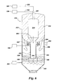
- the gasification assembly 300 comprises a quench chamber 310 in fluid communication with a scrubber (e.g., venturi scrubber) 400.
- a scrubber e.g., venturi scrubber
- the quench chamber 310 may comprise an improved quench chamber as discussed herein that comprises an upper portion 350 and a lower portion 340.
- the lower portion 340 may include a stability baffle 330 configured to dampen water level fluctuation and sloshing.
- Within the lower portion is a reservoir of coolant 502.
- the upper portion 350 may include a baffle 315 that provides a means to remove excess moisture, or water, contained in the existing syngas. In some embodiments, there is no baffle.
- the quench chamber 310 further comprises a dip tube 320 that has a plurality of holes, or perforations 325 therethrough.
- the dip tube 320 extends from the upper portion 350 to the lower portion 340.
- a quench tube is not used. Accordingly, in those embodiments, there is no annular space between the dip tube and quench tube; instead the annular "space" in these embodiments extends all the way from the exterior of the dip tube 320 to the interior face of the upper portion 350 of the quench chamber 310.
- the upper portion 350 further includes a cooling device 360 configured to cool the exiting syngas 506 as it travels towards an exit 370 in the upper portion 350 of the quench chamber 310.
- a mixture of syngas, slag, and fines 500 enters the dip tube 320 from the upstream gasifier 11 ( FIG. 1 ).
- the mixture 500 contacts a coolant 502 that is contained in the second portion 340 of the quench chamber 310.
- the mixture 500 cools upon contact with the coolant 502, wherein slag 504 settles at the bottom of the quench chamber 310.
- a cooled syngas 506 rises off of the coolant 502 above the stability baffles 330.
- the cooling device 360 As the cooled syngas 506 works towards the exit 370 it is further cooled by the cooling device 360.
- the additional cooling provided by the cooling device 360 aids in the further removal of entrained moisture within the syngas thereby providing a dry saturated syngas 508 that exits.
- the dry saturated syngas 508 heads downstream towards the scrubber (e.g., venturi scrubber) 400.
- the dry saturated syngas 508 passes through a transfer line 390 towards a plurality of spray devices 395.
- the spray devices 395 further aid in removing fines and water from the syngas 510.
- a dry syngas 516 ultimately exits the venturi scrubber 400 to head towards, for example, the combustor 39 ( FIG. 1 ).
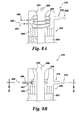
- FIG. 8A a close up sectional view of an upper portion 350 of the quench chamber 310 is depicted.
- the cooling device 360 in the embodiment shown comprises a heat exchanger pipe located within the upper portion 350, above the coolant 502.
- an embodiment includes a cold water input line 362 leading to a helical heat exchanger line 364 which is surrounding the dip tube 320.
- an exit line 366 At the other end of the heat exchanger line 364 is an exit line 366.
- cold water may enter the cold water input line 362.
- the cold water within the heat exchanger line 364 is heated so as to become hot water and/or steam.
- hot water and/or steam exits at the exit line 366 to return to, for example, a heat recovery steam generator 26 ( FIG. 1 ) or other suitable device for reuse.
- the dry saturated syngas 508 exits the exit 370 of quench chamber 310.
- the embodiment shown in FIG. 8A offers several advantages.
- the omission of a draft tube increases quench stability.
- the heat exchanger line 364 also provides a torturous or labyrinthine path for the syngas so that the need for any entrainment baffle(s) is diminished and/or altogether avoided. Further, the reuse of heat obtained by the heat exchanger line 366 increases the overall efficiency of the system.
- FIG. 8B a close up sectional view of an upper portion 350 of the quench chamber 310 of another embodiment is depicted.
- the cooling device 360 in the embodiment shown comprises a plurality of cold water emitters (e.g., sprayers) 368 in the upper portion 350 of the quench chamber 310, above the coolant 502.
- an embodiment includes a plurality of cold water emitters 368 located circumferentially around the periphery of the upper portion 350 of the quench chamber 310.
- the cold water emitters 368 may be distributed uniformly and completely around the periphery with the exception of none being located near the exit 370. In this manner, the cold water emitters 368 are distributed in a perannular pattern.
- a baffle (not shown) may or may not be employed.
- the dry saturated syngas 508 exits the exit 370 of quench chamber 310.
- FIGS. 8B and 9 offer several advantages.
- the omission of a draft tube increases quench stability.
- the perforated dip tube (see e.g., FIG. 7 ) increases stability and syngas aeration.
- additional syngas cooling is providing by the water spray. Any plugging issues at the exit 370 are mitigated by providing the cold water emitters 368 only in the clean gas side of the upper portion 350 of the quench chamber 310.
- aspects of the present invention offer many advantages in the art of gasification quench chamber and scrubber design.
- heat exchanger tubes to cool the syngas in the quench chamber replace the need for any entrainment baffle(s). Effective heat recovery is offered by pre-heating the water for heat recovery steam generator. Further, stability baffle(s) may be used to reduce quench dynamics and avoid sloshing.
- a more effective venturi scrubber is used in lieu of current standard scrubbers.
- Demister assembly is not needed due to the centrifugal separation which aids in the removal of fines in the venturi scrubber.
- quench chamber dip tube, and/or draft tube can be employed without departing from aspects of the present invention.
- FIGS. 4 , 6 , 7 , 8A, and 8B depict a quench chamber having a dip tube-only configuration
- the quench chamber may alternatively have a dip and draft tube tube-only configuration, a dip/draft with a quench ring configuration, and the like.
- the various entrainment mitigation and/or flow damping mechanisms depicted in FIGS. 2-9 may be employed separately or in combination with one another. Moreover, as may be appreciated, the relative sizes, shapes, and geometries of the entrainment mitigation mechanisms may vary.
- the entrainment mitigation and/or flow damping mechanisms may be employed in a quench chamber during the initial manufacturing, or the entrainment mitigation and/or flow damping mechanisms may be retrofit into existing quench units. Further, the entrainment mitigation and/or flow damping mechanisms may be adjusted based on operational parameters, such as the type of carbonaceous fuel, the system efficiency, the system load, or environmental conditions, among others to achieve the desired amount of flow damping.
Landscapes
- Chemical & Material Sciences (AREA)
- Engineering & Computer Science (AREA)
- Combustion & Propulsion (AREA)
- Oil, Petroleum & Natural Gas (AREA)
- Organic Chemistry (AREA)
- Chemical Kinetics & Catalysis (AREA)
- General Chemical & Material Sciences (AREA)
- Physics & Mathematics (AREA)
- Mechanical Engineering (AREA)
- Thermal Sciences (AREA)
- General Engineering & Computer Science (AREA)
- Industrial Gases (AREA)
Applications Claiming Priority (1)
| Application Number | Priority Date | Filing Date | Title |
|---|---|---|---|
| US12/968,423 US9028569B2 (en) | 2009-06-30 | 2010-12-15 | Gasification quench chamber and scrubber assembly |
Publications (3)
| Publication Number | Publication Date |
|---|---|
| EP2465914A2 true EP2465914A2 (fr) | 2012-06-20 |
| EP2465914A3 EP2465914A3 (fr) | 2012-07-11 |
| EP2465914B1 EP2465914B1 (fr) | 2015-11-25 |
Family
ID=45491242
Family Applications (1)
| Application Number | Title | Priority Date | Filing Date |
|---|---|---|---|
| EP11192781.0A Not-in-force EP2465914B1 (fr) | 2010-12-15 | 2011-12-09 | Chambre de trempe de gazéification et ensemble formant épurateur |
Country Status (5)
| Country | Link |
|---|---|
| US (1) | US9028569B2 (fr) |
| EP (1) | EP2465914B1 (fr) |
| KR (1) | KR101872526B1 (fr) |
| CN (1) | CN102585914B (fr) |
| AU (1) | AU2011254034B2 (fr) |
Families Citing this family (19)
| Publication number | Priority date | Publication date | Assignee | Title |
|---|---|---|---|---|
| US20100325954A1 (en) | 2009-06-30 | 2010-12-30 | General Electric Company | Quench chamber assembly for a gasifier |
| US9011559B2 (en) | 2011-08-30 | 2015-04-21 | General Electric Company | Scrubber assembly with guide vanes |
| US8951313B2 (en) | 2012-03-28 | 2015-02-10 | General Electric Company | Gasifier cooling system with convective syngas cooler and quench chamber |
| AU2014278607C1 (en) * | 2013-06-12 | 2018-10-04 | Gas Technology Institute | Entrained-flow gasifier and method for removing molten slag |
| DE102013218830A1 (de) * | 2013-09-19 | 2015-03-19 | Siemens Aktiengesellschaft | Geteiltes Zentralrohr eines kombinierten Quench- und Waschsystems für einen Flugstromvergasungsreaktor |
| US20160061487A1 (en) * | 2014-08-28 | 2016-03-03 | Salvatore Deiana | Apparatus and method for cleaning flue gas |
| JP2017534832A (ja) * | 2014-11-06 | 2017-11-24 | スタルクラブ | 一定の体積の液体を通して気体流を生成して処理するための装置並びに前記装置を実行するための設備及び方法 |
| US9657242B2 (en) | 2015-01-05 | 2017-05-23 | General Electric Company | Quench chamber with integrated scrubber system |
| KR102093053B1 (ko) * | 2015-12-16 | 2020-03-25 | 에어 프로덕츠 앤드 케미칼스, 인코오포레이티드 | 가스화 시스템 및 가스화 방법 |
| JP6663014B2 (ja) * | 2015-12-16 | 2020-03-11 | エア プロダクツ アンド ケミカルズ インコーポレイテッドAir Products And Chemicals Incorporated | ガス化システム及びプロセス |
| WO2018197843A1 (fr) * | 2017-04-24 | 2018-11-01 | Manik Ventures Limited | Appareil de recyclage de matériau |
| US10906808B2 (en) | 2017-11-15 | 2021-02-02 | Gas Technology Institute | Noble metal catalysts and processes for reforming of methane and other hydrocarbons |
| US10738247B2 (en) | 2017-11-15 | 2020-08-11 | Gas Technology Institute | Processes and systems for reforming of methane and light hydrocarbons to liquid hydrocarbon fuels |
| US12122962B2 (en) | 2018-09-18 | 2024-10-22 | Gti Energy | Processes and catalysts for reforming of impure methane-containing feeds |
| CN111692522B (zh) * | 2020-05-09 | 2022-07-12 | 上海工程技术大学 | 气化设备内部圆盘抛形孔状导流结构 |
| CN112175678B (zh) * | 2020-10-29 | 2024-10-15 | 山东能源集团煤气化新材料科技有限公司 | 气化炉及其激冷室 |
| EP4155369A1 (fr) * | 2021-09-23 | 2023-03-29 | L'Air Liquide Société Anonyme pour l'Etude et l'Exploitation des Procédés Georges Claude | Réacteur et procédé de génération d'un gaz produit par gazéification d'un combustible contenant des hydrocarbures |
| CN115181596B (zh) * | 2022-08-02 | 2023-10-27 | 合肥万豪能源设备有限责任公司 | 一种煤层气机械脱水装置 |
| CN119140769B (zh) * | 2024-11-15 | 2025-02-07 | 东北大学 | 一种流线型的振动激冷形核装置及操作方法 |
Family Cites Families (15)
| Publication number | Priority date | Publication date | Assignee | Title |
|---|---|---|---|---|
| US2818326A (en) * | 1956-08-07 | 1957-12-31 | Texas Co | Method of shutting down the gas generator |
| NL178134C (nl) * | 1974-06-17 | 1986-02-03 | Shell Int Research | Werkwijze en inrichting voor het behandelen van een heet produktgas. |
| US4377394A (en) * | 1979-05-30 | 1983-03-22 | Texaco Development Corporation | Apparatus for the production of cleaned and cooled synthesis gas |
| US4778483A (en) | 1987-06-01 | 1988-10-18 | Texaco Inc. | Gasification reactor with internal gas baffling and liquid collector |
| US5415673A (en) | 1993-10-15 | 1995-05-16 | Texaco Inc. | Energy efficient filtration of syngas cooling and scrubbing water |
| JPH10212487A (ja) * | 1997-01-30 | 1998-08-11 | Ishikawajima Harima Heavy Ind Co Ltd | 石炭ガス化装置 |
| US6312482B1 (en) * | 1998-07-13 | 2001-11-06 | The Babcock & Wilcox Company | Steam generator for gasifying coal |
| DE10004138C2 (de) * | 2000-01-31 | 2002-05-16 | Thermoselect Ag Vaduz | Verfahren und Vorrichtung zur Entsorgung und Verwertung von Abfallgütern |
| CA2648683C (fr) * | 2006-04-12 | 2014-11-18 | Shell Internationale Research Maatschappij B.V. | Appareil et procede de refroidissement de gaz chaud |
| US9051522B2 (en) * | 2006-12-01 | 2015-06-09 | Shell Oil Company | Gasification reactor |
| JP5420426B2 (ja) * | 2007-03-15 | 2014-02-19 | シエル・インターナシヨネイル・リサーチ・マーチヤツピイ・ベー・ウイ | 内部多管壁及び複数バーナーを有するガス化反応容器 |
| US8236071B2 (en) | 2007-08-15 | 2012-08-07 | General Electric Company | Methods and apparatus for cooling syngas within a gasifier system |
| US7846226B2 (en) | 2008-02-13 | 2010-12-07 | General Electric Company | Apparatus for cooling and scrubbing a flow of syngas and method of assembling |
| US8197564B2 (en) | 2008-02-13 | 2012-06-12 | General Electric Company | Method and apparatus for cooling syngas within a gasifier system |
| US8986403B2 (en) * | 2009-06-30 | 2015-03-24 | General Electric Company | Gasification system flow damping |
-
2010
- 2010-12-15 US US12/968,423 patent/US9028569B2/en active Active
-
2011
- 2011-12-09 EP EP11192781.0A patent/EP2465914B1/fr not_active Not-in-force
- 2011-12-14 AU AU2011254034A patent/AU2011254034B2/en not_active Ceased
- 2011-12-14 KR KR1020110134703A patent/KR101872526B1/ko active Active
- 2011-12-15 CN CN201110437081.8A patent/CN102585914B/zh active Active
Non-Patent Citations (1)
| Title |
|---|
| None |
Also Published As
| Publication number | Publication date |
|---|---|
| US9028569B2 (en) | 2015-05-12 |
| EP2465914B1 (fr) | 2015-11-25 |
| CN102585914A (zh) | 2012-07-18 |
| US20110120010A1 (en) | 2011-05-26 |
| KR20120067303A (ko) | 2012-06-25 |
| AU2011254034A1 (en) | 2012-07-05 |
| KR101872526B1 (ko) | 2018-06-28 |
| CN102585914B (zh) | 2016-04-13 |
| EP2465914A3 (fr) | 2012-07-11 |
| AU2011254034B2 (en) | 2016-09-01 |
Similar Documents
| Publication | Publication Date | Title |
|---|---|---|
| US9028569B2 (en) | Gasification quench chamber and scrubber assembly | |
| CN101935554B (zh) | 气化系统流动阻尼 | |
| JP5137392B2 (ja) | 部分的調整剤バイパスのための方法およびシステム | |
| US7670574B2 (en) | Methods and apparatus to facilitate cooling syngas in a gasifier | |
| CN101589129B (zh) | 促进气化器中合成气冷却的方法和设备 | |
| US20090202403A1 (en) | Method and apparatus for cooling syngas within a gasifier system | |
| CN105143414B (zh) | 产生无颗粒的冷却合成气的方法和系统 | |
| US20110120009A1 (en) | Gasification quench chamber dip tube | |
| CN104726138A (zh) | 合成气冷却器 | |
| KR101948245B1 (ko) | 인젝터 팁의 냉각 방법 및 장치 | |
| US8151716B2 (en) | Feed injector cooling apparatus and method of assembly | |
| CN108410517B (zh) | 气化激冷系统 | |
| US20130168608A1 (en) | Method for the generation of synthesis gas | |
| US10131856B2 (en) | Gasification quench system |
Legal Events
| Date | Code | Title | Description |
|---|---|---|---|
| PUAL | Search report despatched |
Free format text: ORIGINAL CODE: 0009013 |
|
| PUAI | Public reference made under article 153(3) epc to a published international application that has entered the european phase |
Free format text: ORIGINAL CODE: 0009012 |
|
| AK | Designated contracting states |
Kind code of ref document: A2 Designated state(s): AL AT BE BG CH CY CZ DE DK EE ES FI FR GB GR HR HU IE IS IT LI LT LU LV MC MK MT NL NO PL PT RO RS SE SI SK SM TR |
|
| AX | Request for extension of the european patent |
Extension state: BA ME |
|
| AK | Designated contracting states |
Kind code of ref document: A3 Designated state(s): AL AT BE BG CH CY CZ DE DK EE ES FI FR GB GR HR HU IE IS IT LI LT LU LV MC MK MT NL NO PL PT RO RS SE SI SK SM TR |
|
| AX | Request for extension of the european patent |
Extension state: BA ME |
|
| RIC1 | Information provided on ipc code assigned before grant |
Ipc: C10J 3/20 20060101ALI20120606BHEP Ipc: C10J 3/82 20060101AFI20120606BHEP Ipc: C10J 3/72 20060101ALI20120606BHEP |
|
| 17P | Request for examination filed |
Effective date: 20130111 |
|
| 17Q | First examination report despatched |
Effective date: 20131220 |
|
| 17Q | First examination report despatched |
Effective date: 20140114 |
|
| 17Q | First examination report despatched |
Effective date: 20140123 |
|
| 17Q | First examination report despatched |
Effective date: 20140204 |
|
| REG | Reference to a national code |
Ref country code: DE Ref legal event code: R079 Ref document number: 602011021743 Country of ref document: DE Free format text: PREVIOUS MAIN CLASS: C10J0003820000 Ipc: C10J0003840000 |
|
| GRAP | Despatch of communication of intention to grant a patent |
Free format text: ORIGINAL CODE: EPIDOSNIGR1 |
|
| RIC1 | Information provided on ipc code assigned before grant |
Ipc: C10J 3/76 20060101ALI20150529BHEP Ipc: C10J 3/48 20060101ALI20150529BHEP Ipc: C10J 3/74 20060101ALI20150529BHEP Ipc: C10J 3/84 20060101AFI20150529BHEP |
|
| INTG | Intention to grant announced |
Effective date: 20150626 |
|
| GRAJ | Information related to disapproval of communication of intention to grant by the applicant or resumption of examination proceedings by the epo deleted |
Free format text: ORIGINAL CODE: EPIDOSDIGR1 |
|
| GRAP | Despatch of communication of intention to grant a patent |
Free format text: ORIGINAL CODE: EPIDOSNIGR1 |
|
| GRAS | Grant fee paid |
Free format text: ORIGINAL CODE: EPIDOSNIGR3 |
|
| INTG | Intention to grant announced |
Effective date: 20150916 |
|
| GRAA | (expected) grant |
Free format text: ORIGINAL CODE: 0009210 |
|
| AK | Designated contracting states |
Kind code of ref document: B1 Designated state(s): AL AT BE BG CH CY CZ DE DK EE ES FI FR GB GR HR HU IE IS IT LI LT LU LV MC MK MT NL NO PL PT RO RS SE SI SK SM TR |
|
| REG | Reference to a national code |
Ref country code: GB Ref legal event code: FG4D |
|
| REG | Reference to a national code |
Ref country code: CH Ref legal event code: EP |
|
| REG | Reference to a national code |
Ref country code: AT Ref legal event code: REF Ref document number: 762605 Country of ref document: AT Kind code of ref document: T Effective date: 20151215 |
|
| REG | Reference to a national code |
Ref country code: IE Ref legal event code: FG4D |
|
| REG | Reference to a national code |
Ref country code: DE Ref legal event code: R096 Ref document number: 602011021743 Country of ref document: DE |
|
| REG | Reference to a national code |
Ref country code: LT Ref legal event code: MG4D |
|
| REG | Reference to a national code |
Ref country code: NL Ref legal event code: MP Effective date: 20160225 |
|
| REG | Reference to a national code |
Ref country code: AT Ref legal event code: MK05 Ref document number: 762605 Country of ref document: AT Kind code of ref document: T Effective date: 20151125 |
|
| PG25 | Lapsed in a contracting state [announced via postgrant information from national office to epo] |
Ref country code: HR Free format text: LAPSE BECAUSE OF FAILURE TO SUBMIT A TRANSLATION OF THE DESCRIPTION OR TO PAY THE FEE WITHIN THE PRESCRIBED TIME-LIMIT Effective date: 20151125 Ref country code: NO Free format text: LAPSE BECAUSE OF FAILURE TO SUBMIT A TRANSLATION OF THE DESCRIPTION OR TO PAY THE FEE WITHIN THE PRESCRIBED TIME-LIMIT Effective date: 20160225 Ref country code: LT Free format text: LAPSE BECAUSE OF FAILURE TO SUBMIT A TRANSLATION OF THE DESCRIPTION OR TO PAY THE FEE WITHIN THE PRESCRIBED TIME-LIMIT Effective date: 20151125 Ref country code: NL Free format text: LAPSE BECAUSE OF FAILURE TO SUBMIT A TRANSLATION OF THE DESCRIPTION OR TO PAY THE FEE WITHIN THE PRESCRIBED TIME-LIMIT Effective date: 20151125 Ref country code: IS Free format text: LAPSE BECAUSE OF FAILURE TO SUBMIT A TRANSLATION OF THE DESCRIPTION OR TO PAY THE FEE WITHIN THE PRESCRIBED TIME-LIMIT Effective date: 20160325 |
|
| PG25 | Lapsed in a contracting state [announced via postgrant information from national office to epo] |
Ref country code: FI Free format text: LAPSE BECAUSE OF FAILURE TO SUBMIT A TRANSLATION OF THE DESCRIPTION OR TO PAY THE FEE WITHIN THE PRESCRIBED TIME-LIMIT Effective date: 20151125 Ref country code: SE Free format text: LAPSE BECAUSE OF FAILURE TO SUBMIT A TRANSLATION OF THE DESCRIPTION OR TO PAY THE FEE WITHIN THE PRESCRIBED TIME-LIMIT Effective date: 20151125 Ref country code: BE Free format text: LAPSE BECAUSE OF NON-PAYMENT OF DUE FEES Effective date: 20151231 Ref country code: GR Free format text: LAPSE BECAUSE OF FAILURE TO SUBMIT A TRANSLATION OF THE DESCRIPTION OR TO PAY THE FEE WITHIN THE PRESCRIBED TIME-LIMIT Effective date: 20160226 Ref country code: RS Free format text: LAPSE BECAUSE OF FAILURE TO SUBMIT A TRANSLATION OF THE DESCRIPTION OR TO PAY THE FEE WITHIN THE PRESCRIBED TIME-LIMIT Effective date: 20151125 Ref country code: LV Free format text: LAPSE BECAUSE OF FAILURE TO SUBMIT A TRANSLATION OF THE DESCRIPTION OR TO PAY THE FEE WITHIN THE PRESCRIBED TIME-LIMIT Effective date: 20151125 Ref country code: PT Free format text: LAPSE BECAUSE OF FAILURE TO SUBMIT A TRANSLATION OF THE DESCRIPTION OR TO PAY THE FEE WITHIN THE PRESCRIBED TIME-LIMIT Effective date: 20160325 Ref country code: PL Free format text: LAPSE BECAUSE OF FAILURE TO SUBMIT A TRANSLATION OF THE DESCRIPTION OR TO PAY THE FEE WITHIN THE PRESCRIBED TIME-LIMIT Effective date: 20151125 Ref country code: AT Free format text: LAPSE BECAUSE OF FAILURE TO SUBMIT A TRANSLATION OF THE DESCRIPTION OR TO PAY THE FEE WITHIN THE PRESCRIBED TIME-LIMIT Effective date: 20151125 |
|
| PG25 | Lapsed in a contracting state [announced via postgrant information from national office to epo] |
Ref country code: CZ Free format text: LAPSE BECAUSE OF FAILURE TO SUBMIT A TRANSLATION OF THE DESCRIPTION OR TO PAY THE FEE WITHIN THE PRESCRIBED TIME-LIMIT Effective date: 20151125 |
|
| REG | Reference to a national code |
Ref country code: CH Ref legal event code: PL |
|
| REG | Reference to a national code |
Ref country code: DE Ref legal event code: R097 Ref document number: 602011021743 Country of ref document: DE |
|
| PG25 | Lapsed in a contracting state [announced via postgrant information from national office to epo] |
Ref country code: DK Free format text: LAPSE BECAUSE OF FAILURE TO SUBMIT A TRANSLATION OF THE DESCRIPTION OR TO PAY THE FEE WITHIN THE PRESCRIBED TIME-LIMIT Effective date: 20151125 Ref country code: SK Free format text: LAPSE BECAUSE OF FAILURE TO SUBMIT A TRANSLATION OF THE DESCRIPTION OR TO PAY THE FEE WITHIN THE PRESCRIBED TIME-LIMIT Effective date: 20151125 Ref country code: RO Free format text: LAPSE BECAUSE OF FAILURE TO SUBMIT A TRANSLATION OF THE DESCRIPTION OR TO PAY THE FEE WITHIN THE PRESCRIBED TIME-LIMIT Effective date: 20151125 Ref country code: SM Free format text: LAPSE BECAUSE OF FAILURE TO SUBMIT A TRANSLATION OF THE DESCRIPTION OR TO PAY THE FEE WITHIN THE PRESCRIBED TIME-LIMIT Effective date: 20151125 Ref country code: EE Free format text: LAPSE BECAUSE OF FAILURE TO SUBMIT A TRANSLATION OF THE DESCRIPTION OR TO PAY THE FEE WITHIN THE PRESCRIBED TIME-LIMIT Effective date: 20151125 |
|
| REG | Reference to a national code |
Ref country code: IE Ref legal event code: MM4A |
|
| PG25 | Lapsed in a contracting state [announced via postgrant information from national office to epo] |
Ref country code: MC Free format text: LAPSE BECAUSE OF FAILURE TO SUBMIT A TRANSLATION OF THE DESCRIPTION OR TO PAY THE FEE WITHIN THE PRESCRIBED TIME-LIMIT Effective date: 20151125 |
|
| PLBE | No opposition filed within time limit |
Free format text: ORIGINAL CODE: 0009261 |
|
| REG | Reference to a national code |
Ref country code: FR Ref legal event code: ST Effective date: 20160831 |
|
| STAA | Information on the status of an ep patent application or granted ep patent |
Free format text: STATUS: NO OPPOSITION FILED WITHIN TIME LIMIT |
|
| GBPC | Gb: european patent ceased through non-payment of renewal fee |
Effective date: 20160225 |
|
| PG25 | Lapsed in a contracting state [announced via postgrant information from national office to epo] |
Ref country code: CH Free format text: LAPSE BECAUSE OF NON-PAYMENT OF DUE FEES Effective date: 20151231 Ref country code: LI Free format text: LAPSE BECAUSE OF NON-PAYMENT OF DUE FEES Effective date: 20151231 Ref country code: IE Free format text: LAPSE BECAUSE OF NON-PAYMENT OF DUE FEES Effective date: 20151209 |
|
| 26N | No opposition filed |
Effective date: 20160826 |
|
| PG25 | Lapsed in a contracting state [announced via postgrant information from national office to epo] |
Ref country code: SI Free format text: LAPSE BECAUSE OF FAILURE TO SUBMIT A TRANSLATION OF THE DESCRIPTION OR TO PAY THE FEE WITHIN THE PRESCRIBED TIME-LIMIT Effective date: 20151125 Ref country code: FR Free format text: LAPSE BECAUSE OF NON-PAYMENT OF DUE FEES Effective date: 20160125 |
|
| PG25 | Lapsed in a contracting state [announced via postgrant information from national office to epo] |
Ref country code: BE Free format text: LAPSE BECAUSE OF FAILURE TO SUBMIT A TRANSLATION OF THE DESCRIPTION OR TO PAY THE FEE WITHIN THE PRESCRIBED TIME-LIMIT Effective date: 20151125 |
|
| PG25 | Lapsed in a contracting state [announced via postgrant information from national office to epo] |
Ref country code: GB Free format text: LAPSE BECAUSE OF NON-PAYMENT OF DUE FEES Effective date: 20160225 |
|
| PGFP | Annual fee paid to national office [announced via postgrant information from national office to epo] |
Ref country code: DE Payment date: 20161229 Year of fee payment: 6 |
|
| PG25 | Lapsed in a contracting state [announced via postgrant information from national office to epo] |
Ref country code: HU Free format text: LAPSE BECAUSE OF FAILURE TO SUBMIT A TRANSLATION OF THE DESCRIPTION OR TO PAY THE FEE WITHIN THE PRESCRIBED TIME-LIMIT; INVALID AB INITIO Effective date: 20111209 Ref country code: BG Free format text: LAPSE BECAUSE OF FAILURE TO SUBMIT A TRANSLATION OF THE DESCRIPTION OR TO PAY THE FEE WITHIN THE PRESCRIBED TIME-LIMIT Effective date: 20151125 |
|
| PG25 | Lapsed in a contracting state [announced via postgrant information from national office to epo] |
Ref country code: CY Free format text: LAPSE BECAUSE OF FAILURE TO SUBMIT A TRANSLATION OF THE DESCRIPTION OR TO PAY THE FEE WITHIN THE PRESCRIBED TIME-LIMIT Effective date: 20151125 |
|
| PG25 | Lapsed in a contracting state [announced via postgrant information from national office to epo] |
Ref country code: ES Free format text: LAPSE BECAUSE OF NON-PAYMENT OF DUE FEES Effective date: 20151125 |
|
| PG25 | Lapsed in a contracting state [announced via postgrant information from national office to epo] |
Ref country code: TR Free format text: LAPSE BECAUSE OF FAILURE TO SUBMIT A TRANSLATION OF THE DESCRIPTION OR TO PAY THE FEE WITHIN THE PRESCRIBED TIME-LIMIT Effective date: 20151125 Ref country code: MT Free format text: LAPSE BECAUSE OF FAILURE TO SUBMIT A TRANSLATION OF THE DESCRIPTION OR TO PAY THE FEE WITHIN THE PRESCRIBED TIME-LIMIT Effective date: 20151125 |
|
| PG25 | Lapsed in a contracting state [announced via postgrant information from national office to epo] |
Ref country code: LU Free format text: LAPSE BECAUSE OF NON-PAYMENT OF DUE FEES Effective date: 20151209 |
|
| PG25 | Lapsed in a contracting state [announced via postgrant information from national office to epo] |
Ref country code: MK Free format text: LAPSE BECAUSE OF FAILURE TO SUBMIT A TRANSLATION OF THE DESCRIPTION OR TO PAY THE FEE WITHIN THE PRESCRIBED TIME-LIMIT Effective date: 20151125 |
|
| REG | Reference to a national code |
Ref country code: DE Ref legal event code: R119 Ref document number: 602011021743 Country of ref document: DE |
|
| PG25 | Lapsed in a contracting state [announced via postgrant information from national office to epo] |
Ref country code: AL Free format text: LAPSE BECAUSE OF FAILURE TO SUBMIT A TRANSLATION OF THE DESCRIPTION OR TO PAY THE FEE WITHIN THE PRESCRIBED TIME-LIMIT Effective date: 20151125 Ref country code: DE Free format text: LAPSE BECAUSE OF NON-PAYMENT OF DUE FEES Effective date: 20180703 |
|
| PGFP | Annual fee paid to national office [announced via postgrant information from national office to epo] |
Ref country code: IT Payment date: 20201110 Year of fee payment: 10 |
|
| PG25 | Lapsed in a contracting state [announced via postgrant information from national office to epo] |
Ref country code: IT Free format text: LAPSE BECAUSE OF NON-PAYMENT OF DUE FEES Effective date: 20211209 |