EP2466025A2 - Support pour matière isolante - Google Patents
Support pour matière isolante Download PDFInfo
- Publication number
- EP2466025A2 EP2466025A2 EP11401646A EP11401646A EP2466025A2 EP 2466025 A2 EP2466025 A2 EP 2466025A2 EP 11401646 A EP11401646 A EP 11401646A EP 11401646 A EP11401646 A EP 11401646A EP 2466025 A2 EP2466025 A2 EP 2466025A2
- Authority
- EP
- European Patent Office
- Prior art keywords
- insulation
- thread
- rib
- insulating
- holder
- Prior art date
- Legal status (The legal status is an assumption and is not a legal conclusion. Google has not performed a legal analysis and makes no representation as to the accuracy of the status listed.)
- Granted
Links
- 238000009413 insulation Methods 0.000 title claims abstract description 129
- 239000011810 insulating material Substances 0.000 claims abstract description 31
- 239000012774 insulation material Substances 0.000 claims description 35
- 238000003780 insertion Methods 0.000 claims description 24
- 230000037431 insertion Effects 0.000 claims description 24
- 230000007704 transition Effects 0.000 description 5
- 238000002347 injection Methods 0.000 description 4
- 239000007924 injection Substances 0.000 description 4
- 230000015572 biosynthetic process Effects 0.000 description 3
- 230000005540 biological transmission Effects 0.000 description 2
- 239000004566 building material Substances 0.000 description 2
- 230000008859 change Effects 0.000 description 2
- 229910052500 inorganic mineral Inorganic materials 0.000 description 2
- 239000011707 mineral Substances 0.000 description 2
- 230000000087 stabilizing effect Effects 0.000 description 2
- 239000004793 Polystyrene Substances 0.000 description 1
- 230000006835 compression Effects 0.000 description 1
- 238000007906 compression Methods 0.000 description 1
- 230000000694 effects Effects 0.000 description 1
- 238000001746 injection moulding Methods 0.000 description 1
- 238000004519 manufacturing process Methods 0.000 description 1
- 230000007246 mechanism Effects 0.000 description 1
- 230000002093 peripheral effect Effects 0.000 description 1
- 229920002223 polystyrene Polymers 0.000 description 1
- 230000009467 reduction Effects 0.000 description 1
- 230000007480 spreading Effects 0.000 description 1
- 239000000126 substance Substances 0.000 description 1
- 239000000758 substrate Substances 0.000 description 1
- 239000002023 wood Substances 0.000 description 1
Images

Classifications
-
- E—FIXED CONSTRUCTIONS
- E04—BUILDING
- E04B—GENERAL BUILDING CONSTRUCTIONS; WALLS, e.g. PARTITIONS; ROOFS; FLOORS; CEILINGS; INSULATION OR OTHER PROTECTION OF BUILDINGS
- E04B1/00—Constructions in general; Structures which are not restricted either to walls, e.g. partitions, or floors or ceilings or roofs
- E04B1/62—Insulation or other protection; Elements or use of specified material therefor
- E04B1/74—Heat, sound or noise insulation, absorption, or reflection; Other building methods affording favourable thermal or acoustical conditions, e.g. accumulating of heat within walls
- E04B1/76—Heat, sound or noise insulation, absorption, or reflection; Other building methods affording favourable thermal or acoustical conditions, e.g. accumulating of heat within walls specifically with respect to heat only
- E04B1/762—Exterior insulation of exterior walls
- E04B1/7629—Details of the mechanical connection of the insulation to the wall
- E04B1/7633—Dowels with enlarged insulation retaining head
-
- F—MECHANICAL ENGINEERING; LIGHTING; HEATING; WEAPONS; BLASTING
- F16—ENGINEERING ELEMENTS AND UNITS; GENERAL MEASURES FOR PRODUCING AND MAINTAINING EFFECTIVE FUNCTIONING OF MACHINES OR INSTALLATIONS; THERMAL INSULATION IN GENERAL
- F16B—DEVICES FOR FASTENING OR SECURING CONSTRUCTIONAL ELEMENTS OR MACHINE PARTS TOGETHER, e.g. NAILS, BOLTS, CIRCLIPS, CLAMPS, CLIPS OR WEDGES; JOINTS OR JOINTING
- F16B13/00—Dowels or other devices fastened in walls or the like by inserting them in holes made therein for that purpose
- F16B13/001—Dowels or other devices fastened in walls or the like by inserting them in holes made therein for that purpose with means for preventing rotation of the dowel
-
- F—MECHANICAL ENGINEERING; LIGHTING; HEATING; WEAPONS; BLASTING
- F16—ENGINEERING ELEMENTS AND UNITS; GENERAL MEASURES FOR PRODUCING AND MAINTAINING EFFECTIVE FUNCTIONING OF MACHINES OR INSTALLATIONS; THERMAL INSULATION IN GENERAL
- F16B—DEVICES FOR FASTENING OR SECURING CONSTRUCTIONAL ELEMENTS OR MACHINE PARTS TOGETHER, e.g. NAILS, BOLTS, CIRCLIPS, CLAMPS, CLIPS OR WEDGES; JOINTS OR JOINTING
- F16B13/00—Dowels or other devices fastened in walls or the like by inserting them in holes made therein for that purpose
- F16B13/02—Dowels or other devices fastened in walls or the like by inserting them in holes made therein for that purpose in one piece with protrusions or ridges on the shaft
-
- F—MECHANICAL ENGINEERING; LIGHTING; HEATING; WEAPONS; BLASTING
- F16—ENGINEERING ELEMENTS AND UNITS; GENERAL MEASURES FOR PRODUCING AND MAINTAINING EFFECTIVE FUNCTIONING OF MACHINES OR INSTALLATIONS; THERMAL INSULATION IN GENERAL
- F16B—DEVICES FOR FASTENING OR SECURING CONSTRUCTIONAL ELEMENTS OR MACHINE PARTS TOGETHER, e.g. NAILS, BOLTS, CIRCLIPS, CLAMPS, CLIPS OR WEDGES; JOINTS OR JOINTING
- F16B13/00—Dowels or other devices fastened in walls or the like by inserting them in holes made therein for that purpose
- F16B13/12—Separate metal or non-separate or non-metal dowel sleeves fastened by inserting the screw, nail or the like
- F16B13/124—Separate metal or non-separate or non-metal dowel sleeves fastened by inserting the screw, nail or the like fastened by inserting a threaded element, e.g. screw or bolt
-
- F—MECHANICAL ENGINEERING; LIGHTING; HEATING; WEAPONS; BLASTING
- F16—ENGINEERING ELEMENTS AND UNITS; GENERAL MEASURES FOR PRODUCING AND MAINTAINING EFFECTIVE FUNCTIONING OF MACHINES OR INSTALLATIONS; THERMAL INSULATION IN GENERAL
- F16B—DEVICES FOR FASTENING OR SECURING CONSTRUCTIONAL ELEMENTS OR MACHINE PARTS TOGETHER, e.g. NAILS, BOLTS, CIRCLIPS, CLAMPS, CLIPS OR WEDGES; JOINTS OR JOINTING
- F16B25/00—Screws that cut thread in the body into which they are screwed, e.g. wood screws
- F16B25/001—Screws that cut thread in the body into which they are screwed, e.g. wood screws characterised by the material of the body into which the screw is screwed
- F16B25/0015—Screws that cut thread in the body into which they are screwed, e.g. wood screws characterised by the material of the body into which the screw is screwed the material being a soft organic material, e.g. wood or plastic
Definitions
- the invention relates to an insulation holder with the features of the preamble of claim 1.
- insulation holders For the attachment of insulating panels to buildings, such as polystyrene panels of thermal insulation systems, insulation holders are used. Insulation holders with holding plates, which rest against the insulating material and fasten the insulating plate to the substrate, are widespread. Such an insulation holder is for example from the published patent application DE 10 2005 046 092 A1 known. From the European patent application EP 2 213 888 A2 an insulating material holder is known, which has an insulating thread instead of the retaining plate for fixing an insulating plate to a mounting base. The insulation thread of the insulation holder is screwed into the insulation material, wherein the insulation thread in the insulation material cuts a thread, so that the insulation thread is positively connected to the insulation material.
- the insulating thread has a relatively large outer diameter and a relatively small relative to this core diameter.
- the flanks of the insulation thread are made relatively large and flat, in order to activate the largest possible surface of the insulating material for the power transmission with the insulation material thread. Due to the flat concerns of the thread flanks in the insulating material, the insulating thread acts as a retaining plate of a common insulation holder.
- the outer diameter of the insulation thread is at least 60 mm, with a core diameter that usually does not exceed 20 mm.
- the thread flanks are typically relatively flat and even with a height of only a few millimeters.
- a disadvantage of the known insulation holders with insulation thread that, due to the flat contact of the insulation material thread in the insulation material and the relatively large areas of the thread flanks, the screwing resistance of the insulation material holder is relatively large.
- the object of the invention is therefore to propose an insulation holder with insulation thread, which is easily screwed into the insulation material.
- the insulation holder according to the invention for fastening an insulation panel to a mounting base has an insulation thread, which can be screwed into the insulation plate.
- a thread is cut in the insulation, so that the insulation thread is positively connected to the insulation.
- Forces acting on the insulation board for example, by wind suction, are transferred to the base of the insulation via the insulation thread on the insulation holder and via a fastening element with which the insulation holder is fastened in the fastening ground.
- the fastener is formed, for example, as a dowel with expansion element.
- the fastener may be, for example, a plug, a screw or a nail.
- a chemical attachment is possible.
- An insulating thread is, as known from the prior art, typically formed as a helical thread with flat thread flanks, wherein the thread flanks have a large diameter relative to the threaded core. The thread flanks cut into the insulation and are to activate the largest possible area of the insulation, so that even relatively large forces between the insulation material thread and the insulating material, which is relatively soft compared to mineral building materials or wood, can be transmitted.
- thread flanks in this context, the insulating thread forming surfaces are meant. In principle, it is also conceivable to subdivide the insulation material threads into individual threaded sections, which can be connected to one another.
- Characteristic of the insulation holder according to the invention is that the insulation thread at least one rib is arranged, which extends in the circumferential direction.
- the term "rib" in this context includes any geometric shape that is band-shaped on the insulation thread and increases the cross section of the insulation material thread in and / or against the direction of insertion into the insulation material beyond the cross section of the flanks and the flank in and / or against the Inserted at least locally overrun.
- a rib may, for example, have a rectangular, triangular or semicircular cross section.
- the transition from one flank of the insulation thread to the rib can be sudden.
- the transition from the edge to the rib may be continuous, for example, the transition may be rounded.
- “Circumferential direction” refers to the longitudinal axis of the insulating material holder pointing in the direction of insertion, the circumferential direction being tangential to a cylinder circumscribing the insulating material holder.
- the effect of the rib is that when the insulating thread is not screwed into the insulating material, the insulating material is no longer fully applied to the thread flanks of the insulating thread. The rib pushes the insulating material away from the thread flank on which the rib is arranged, whereby the contact surface between the insulating thread and the insulating material is reduced.
- the insertion resistance of the insulation material holder is reduced because less friction between the thread flanks and the insulating material is created by the reduced contact surfaces. Due to the reduced insertion resistance, the insulation holder is easier to screw into the insulation material. After the insertion of the insulating material holder, the insulating material deforms back as far as possible to its original shape, so that it then rests over the entire surface on the flanks of the insulation thread and substantially the entire surface of the insulation material thread is available for power transmission.
- the insulation holder according to the invention can thus transmit large forces from the insulation board to the mounting base despite the low Einfwiderstands.
- the rib extends substantially beyond the surface of the insulation material thread in the insertion direction.
- “Overhanging” here means that the rib not only projects locally beyond the surface of the thread flank, but that, with respect to a radially extending cross-section, it projects beyond the entire surface of the thread flank on which the rib is arranged.
- the rib is arranged substantially on the circumference of the insulation material thread.
- circumference is meant the part of the thread flank furthest away from the longitudinal axis with respect to a cross-section extending in the radial direction.
- a cutting edge is arranged in the radial direction on the rib arranged substantially at the circumference of the insulating material thread.
- the cutting edge may be formed as a circumferentially extending band, as a localized portion or as a plurality of portions.
- At least one rib extends substantially over the entire length of the insulation material thread.
- total length means that the rib is also divided into several sections and arranged on each of the sections of the insulation thread. This ensures that when screwing the contact surface against which abuts the thread flanks during the insertion of the insulating material, is substantially reduced over the entire length of the insulation thread.
- the insertion resistance will thus increase continuously until a maximum is reached when the insulation thread is completely submerged in the insulation. A sudden change in the insertion resistance is avoided due to the formation of the rib substantially over the entire length of the insulation thread.
- At least one rib is formed as a circular ring.
- the rib is not designed as a closed circular ring, but like the insulation thread helically, the rib may include only a portion of a circular ring.
- “As annulus” means that the distance of the rib from the longitudinal axis of the insulation material holder does not change substantially or only slightly. Such a rib not only reduces the screwing resistance of the insulation holder, it also has a stabilizing effect.
- Stabilizing means that the annular rib prevents the insulation holder from tilting and running counter to the original driving direction when it is screwed into the insulation material. Thus, it is prevented that the insulation holder is tilted and not, as usual, normal to the surface of the insulation board is introduced into the insulation.
- a plurality of ribs are arranged on the insulation thread, which are distributed uniformly in the radial direction over the insulation material thread substantially.
- the insulation thread extends over more than one revolution.
- the insulation thread is designed for this purpose so that do not overlap in the direction of insertion successive sections of the insulation thread.
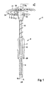
- the insulation holder 1 for attachment of an insulating plate, not shown, to a mounting base, also not shown, has a threaded sleeve 2 with an insulating thread 3 and a holder shaft 4, which is arranged in the direction of insertion E in front of the threaded sleeve 2.
- the holder shank 4 is essentially designed as a cylindrical hollow body which extends in the direction of the longitudinal axis L of the insulating material holder 1.
- the holder shaft 4 has at its front end in the direction of insertion E as a fastening element 5 an expansion dowel, to which a hollow cylindrical shaft portion 6 is connected. Trained as expansion dowel fastener 5 is used to attach the insulation holder 1 in a mounting ground, for example, in a wall of concrete.
- Trained as expansion dowel fastener 5 is used to attach the insulation holder 1 in a mounting ground, for example, in a wall of concrete.
- Arranged on the hollow-cylindrical shank portion 6 are two arcuate wing elements 7, which project beyond the fastening element 5 and the shank portion 6 in the radial direction R and are connected to the shank portion 6 at its front and rear ends.
- the rear end of the holder shaft 4 forms an upsetting region 8, to which the threaded sleeve 2 is connected.
- the swaged region 8 has a wall thickness which is smaller than the shaft section 6, as a result of which the swage region 8 can be compressed in the direction of the longitudinal axis L.
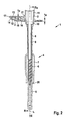
- the fastening element 5, the shank section 6 with the wing elements 7 and the swaged area 8 are embodied in one piece as an injection-molded part. As in FIG. 2 can be seen, is located in a hollow cylindrical portion 11 of the threaded sleeve 2, a screw 9 as a spreading element for the formed as expansion dowel fastener 5 a.
- the hollow cylindrical portion 11 has a hollow cross section in the form of a hexagon, which corresponds to the head 10 of the screw 9 such that the head 10 of the screw 9 is clamped in the threaded sleeve 2 and that the threaded sleeve 2 and the screw 9 rotatably connected to each other are.
- the insulation thread 3 is arranged in one piece.
- the threaded sleeve 2 is also manufactured as an injection molded part.
- the hollow cylindrical portion 11 of the threaded sleeve 2 forms the thread core of the insulation material thread 3.
- the hollow cylindrical portion 11 has a relation to the longitudinal axis L diameter D K of 15 mm.
- the maximum diameter D D of the insulation thread is 66 mm.
- the two thread flanks 12, 13 of the insulation thread 3 are substantially parallel, with the insulation thread has a thickness t D of 1.5 mm.
- the insulation thread 3 is thus formed as a helical thread with flat thread flanks 12, 13, wherein the thread flanks 12, 13 have a large diameter D D in relation to the hollow cylindrical portion 11.
- the thread flanks 12, 13 form the front and the rear surface of the insulation material thread 2, wherein "front” and “rear” refers to the insertion direction E.
- ribs 14, 15, 16 are arranged, which extend in the circumferential direction U.
- the ribs 14, 15, 16 have a thickness t R of 3 mm and extend beyond the surfaces of the insulation thread 3, so the surfaces of the two thread flanks 12, 13 in and against the insertion direction E by 0.75 mm.
- "projecting" in this context means that the ribs 14, 15, 16 not only locally over the surfaces of the thread flanks 12, 13 survive, but that, based on the in FIG. 2 projecting in the radial direction extending cross section, the entire surface of the thread flanks 12, 13 project beyond, with the directly adjacent to the hollow cylindrical portion 11 rounded transition region 21 is excluded.
- a first rib 14 is arranged substantially on the circumference of the insulation material thread 3.
- the first rib 14 has, in the radial direction R, a circumferential cutting edge 17 which, like the ribs 14, 15, 16, extends substantially over the entire length of the insulating material thread 3.
- the cutting edge 17 is triangular in cross-section, with a tip of the triangle pointing in the radial direction R.
- the three ribs 14, 15, 16 are each formed as part of a helical circular ring, that is, the annuli are not closed, the rear end in the insertion direction and the front end of the ribs 14, 15, 16, based on the longitudinal axis L of Insulation holder 1, one behind the other.
- Each of the ribs 14, 15, 16 has a substantially constant distance to the longitudinal axis L of the insulating material holder 1.
- the three ribs 14, 15, 16 are distributed uniformly in the radial direction R over the insulating thread, that is to say the distances in the radial direction between the first rib 14 and the second rib 15, between the second rib 15 and the third rib 16 and between the third rib 16 and the hollow cylindrical portion 11 of the insulation thread 3 are substantially equal and about 15 mm.
- the three ribs 14, 15, 16 also stabilize the insulation thread 3 and thus allow its small thickness t D , whereby the insertion resistance is also reduced.
- the insulation thread 3 of the insulation holder 1 extends over more than one revolution, ie by more than 360 ° relative to the longitudinal axis L.
- the insulation thread 3 begins in a front portion 18 with the peripheral cutting edge 17 directly on the hollow cylindrical portion 11, wherein the insulation thread 3 in the front portion 18 spirally extends until the maximum outer diameter D D of the insulation thread 3 is reached.
- the insulation material thread 3 is no longer connected directly to the hollow cylindrical portion 11 in the radial direction.
- the insulation thread 3 is designed in this area such that in the direction of insertion E successive portions of the insulation thread 3 do not overlap, that is, that the front portion 18 and the rear portion 19 in the plan view of FIG. 3 do not lie on top of each other. Because of this design, the threaded sleeve 2 can be inexpensively manufactured as an injection molded part, since the injection molding tool requires no complicated mechanism for demolding the injection molded part.
- a hole is first introduced into the insulation board and in the mounting base and the insulation holder 1 with its front end, the fastener 5, inserted into the hole until the insulation thread 3 is applied to the insulating material.
- the fastener 5 By turning the insulation thread 3 of the insulation holder 1 is sunk in the insulation.
- the wing elements 7 act as a depth stop for the insulation holder 1 due to a trained at its front end stop shoulder 20 abuts the stop shoulder 20 on the mounting base, the holder shaft 4 is no longer in the direction the introduction direction E are introduced into the bore.
- the screw 9 is forcibly moved by means of the threaded sleeve 2 in the direction of the insertion direction E, whereby the compression region 8 is compressed and shortened.
- the screw 9 penetrates into the fastening element 5 configured as an expansion dowel, whereby the expansion dowel is expanded and the insulation holder 1 is fastened in the fastening base.
- the insulation thread 3 intersects a thread in the insulating material, wherein the cutting of the thread is facilitated by the formation of the cutting edge 17 on the circumference of the insulation thread 3.
Landscapes
- Engineering & Computer Science (AREA)
- General Engineering & Computer Science (AREA)
- Mechanical Engineering (AREA)
- Physics & Mathematics (AREA)
- Architecture (AREA)
- Acoustics & Sound (AREA)
- Electromagnetism (AREA)
- Civil Engineering (AREA)
- Structural Engineering (AREA)
- Insulating Bodies (AREA)
- Bolts, Nuts, And Washers (AREA)
- Installation Of Bus-Bars (AREA)
Priority Applications (1)
| Application Number | Priority Date | Filing Date | Title |
|---|---|---|---|
| PL11401646T PL2466025T3 (pl) | 2010-12-16 | 2011-12-01 | Uchwyt izolacji |
Applications Claiming Priority (1)
| Application Number | Priority Date | Filing Date | Title |
|---|---|---|---|
| DE102010061283A DE102010061283A1 (de) | 2010-12-16 | 2010-12-16 | Dämmstoffhalter |
Publications (3)
| Publication Number | Publication Date |
|---|---|
| EP2466025A2 true EP2466025A2 (fr) | 2012-06-20 |
| EP2466025A3 EP2466025A3 (fr) | 2013-07-17 |
| EP2466025B1 EP2466025B1 (fr) | 2015-07-29 |
Family
ID=45319039
Family Applications (1)
| Application Number | Title | Priority Date | Filing Date |
|---|---|---|---|
| EP11401646.2A Not-in-force EP2466025B1 (fr) | 2010-12-16 | 2011-12-01 | Support pour matière isolante |
Country Status (3)
| Country | Link |
|---|---|
| EP (1) | EP2466025B1 (fr) |
| DE (1) | DE102010061283A1 (fr) |
| PL (1) | PL2466025T3 (fr) |
Cited By (4)
| Publication number | Priority date | Publication date | Assignee | Title |
|---|---|---|---|---|
| EP2757206A3 (fr) * | 2013-01-16 | 2016-07-06 | Frank Mitterlindner | Support pour matière isolante |
| EP3173632A1 (fr) * | 2015-11-30 | 2017-05-31 | SFS intec Holding AG | Ancrage pour béton, système d'ancrage pour béton, système de fixation et procédé de fabrication d'un système de fixation |
| EP2905392B1 (fr) * | 2014-02-06 | 2021-07-28 | fischerwerke GmbH & Co. KG | Procédé de pose pour la fixation d'isolants |
| EP3862580A1 (fr) * | 2020-02-07 | 2021-08-11 | Adolf Würth GmbH & Co. KG | Dispositif de fixation comprenant une vis et un corps isolant thermique fixé à celle-ci d'une manière rotative et bloquée axialement |
Families Citing this family (4)
| Publication number | Priority date | Publication date | Assignee | Title |
|---|---|---|---|---|
| DE102012106745B4 (de) * | 2012-07-25 | 2022-03-03 | Fischerwerke Gmbh & Co. Kg | Werkzeug für die Montage eines Dämmstoffdübels |
| DE202014009615U1 (de) | 2013-12-06 | 2015-03-20 | Fröwis Aktiengesellschaft | Befestigungsvorrichtung zur Befestigung eines Dämmstoffs |
| DE102017126059A1 (de) | 2017-10-11 | 2019-04-11 | Fischerwerke Gmbh & Co. Kg | Dämmstoffdübel und Befestigungsanordnung |
| EP3470591A1 (fr) | 2017-10-11 | 2019-04-17 | fischerwerke GmbH & Co. KG | Dispositif de fixation de matériau isolant |
Citations (10)
| Publication number | Priority date | Publication date | Assignee | Title |
|---|---|---|---|---|
| EP0811773A2 (fr) | 1996-06-07 | 1997-12-10 | Holzinger, Alois, sen. | Dispositif pour la fixation à distance de plaques d'isolation aux murs |
| DE102004062151A1 (de) | 2004-12-23 | 2006-07-13 | Fischerwerke Artur Fischer Gmbh & Co. Kg | Befestigungselement für Dämmstoffplatten |
| DE102005046092A1 (de) | 2005-09-27 | 2007-03-29 | Fischerwerke Artur Fischer Gmbh & Co. Kg | Spreizdübel für die Befestigung von Dämmstoffplatten |
| DE102005000147A1 (de) | 2005-11-02 | 2007-05-03 | Hilti Ag | Befestigungselement für die Befestigung von Dämmstoffplatten |
| DE102007053740B3 (de) | 2007-11-12 | 2009-01-15 | Ejot Baubefestigungen Gmbh | Universaldübel für Wärmedämmverbundsysteme |
| DE102007000758A1 (de) | 2007-09-20 | 2009-04-09 | Hilti Aktiengesellschaft | Befestigungselement für die Befestigung von Dämmstoffplatten an einer Unterkonstruktion |
| DE102007000759A1 (de) | 2007-09-20 | 2009-04-09 | Hilti Aktiengesellschaft | Befestigungselement für die Befestigung von Dämmstoffplatten an einer Unterkonstruktion |
| DE102008058512A1 (de) | 2007-12-05 | 2009-06-10 | Ranit-Befestigungssysteme Gmbh | Verfahren und Befestigungssystem zum Anbringen von Dämmstoffplatten sowie einen Dübel und einen Halteteller |
| DE202008002183U1 (de) | 2008-02-16 | 2009-06-25 | Reuter, Werner | Spreizdübel |
| EP2213888A2 (fr) | 2009-01-30 | 2010-08-04 | fischerwerke GmbH & Co. KG | Support pour matière isolante |
Family Cites Families (1)
| Publication number | Priority date | Publication date | Assignee | Title |
|---|---|---|---|---|
| DE102006060538A1 (de) * | 2006-05-15 | 2007-11-22 | Fischerwerke Artur Fischer Gmbh & Co. Kg | Befestigungselement und Verfahren zur Befestigung von Dämmstoffplatten |
-
2010
- 2010-12-16 DE DE102010061283A patent/DE102010061283A1/de not_active Withdrawn
-
2011
- 2011-12-01 EP EP11401646.2A patent/EP2466025B1/fr not_active Not-in-force
- 2011-12-01 PL PL11401646T patent/PL2466025T3/pl unknown
Patent Citations (10)
| Publication number | Priority date | Publication date | Assignee | Title |
|---|---|---|---|---|
| EP0811773A2 (fr) | 1996-06-07 | 1997-12-10 | Holzinger, Alois, sen. | Dispositif pour la fixation à distance de plaques d'isolation aux murs |
| DE102004062151A1 (de) | 2004-12-23 | 2006-07-13 | Fischerwerke Artur Fischer Gmbh & Co. Kg | Befestigungselement für Dämmstoffplatten |
| DE102005046092A1 (de) | 2005-09-27 | 2007-03-29 | Fischerwerke Artur Fischer Gmbh & Co. Kg | Spreizdübel für die Befestigung von Dämmstoffplatten |
| DE102005000147A1 (de) | 2005-11-02 | 2007-05-03 | Hilti Ag | Befestigungselement für die Befestigung von Dämmstoffplatten |
| DE102007000758A1 (de) | 2007-09-20 | 2009-04-09 | Hilti Aktiengesellschaft | Befestigungselement für die Befestigung von Dämmstoffplatten an einer Unterkonstruktion |
| DE102007000759A1 (de) | 2007-09-20 | 2009-04-09 | Hilti Aktiengesellschaft | Befestigungselement für die Befestigung von Dämmstoffplatten an einer Unterkonstruktion |
| DE102007053740B3 (de) | 2007-11-12 | 2009-01-15 | Ejot Baubefestigungen Gmbh | Universaldübel für Wärmedämmverbundsysteme |
| DE102008058512A1 (de) | 2007-12-05 | 2009-06-10 | Ranit-Befestigungssysteme Gmbh | Verfahren und Befestigungssystem zum Anbringen von Dämmstoffplatten sowie einen Dübel und einen Halteteller |
| DE202008002183U1 (de) | 2008-02-16 | 2009-06-25 | Reuter, Werner | Spreizdübel |
| EP2213888A2 (fr) | 2009-01-30 | 2010-08-04 | fischerwerke GmbH & Co. KG | Support pour matière isolante |
Cited By (4)
| Publication number | Priority date | Publication date | Assignee | Title |
|---|---|---|---|---|
| EP2757206A3 (fr) * | 2013-01-16 | 2016-07-06 | Frank Mitterlindner | Support pour matière isolante |
| EP2905392B1 (fr) * | 2014-02-06 | 2021-07-28 | fischerwerke GmbH & Co. KG | Procédé de pose pour la fixation d'isolants |
| EP3173632A1 (fr) * | 2015-11-30 | 2017-05-31 | SFS intec Holding AG | Ancrage pour béton, système d'ancrage pour béton, système de fixation et procédé de fabrication d'un système de fixation |
| EP3862580A1 (fr) * | 2020-02-07 | 2021-08-11 | Adolf Würth GmbH & Co. KG | Dispositif de fixation comprenant une vis et un corps isolant thermique fixé à celle-ci d'une manière rotative et bloquée axialement |
Also Published As
| Publication number | Publication date |
|---|---|
| RU2011151411A (ru) | 2013-06-20 |
| EP2466025B1 (fr) | 2015-07-29 |
| DE102010061283A1 (de) | 2012-06-21 |
| PL2466025T3 (pl) | 2015-12-31 |
| EP2466025A3 (fr) | 2013-07-17 |
Similar Documents
| Publication | Publication Date | Title |
|---|---|---|
| EP2466025B1 (fr) | Support pour matière isolante | |
| EP2213888B1 (fr) | Support pour matière isolante | |
| DE69614593T2 (de) | Verankerungseinheit mit einem durch das auf den Bolzen einwirkende Drehmoment ausweitbaren Verankerungsteil | |
| EP2326848B1 (fr) | Vis | |
| EP3006748B1 (fr) | Vis autotaraudeuse | |
| EP3577350B1 (fr) | Cheville de plaque de plâtre | |
| DE102024112582A1 (de) | Trockenbaudübel und Verfahren zur Montage des Trockenbaudübels | |
| DE102008010606A1 (de) | Befestigungselement für Holzfaserdämmplatten | |
| EP3045740B1 (fr) | Élément de fixation destiné à fixer un composant sur un système composite d'isolation thermique | |
| WO2005017372A1 (fr) | Dispositif comportant deux profiles creux assembles par une vis et outil correspondant | |
| EP3477127B1 (fr) | Vis destinée à être vissée dans un trou de forage | |
| DE102005008779B3 (de) | Gewindeelement | |
| EP3548755B1 (fr) | Élément fileté ainsi que raccord pouvant être créé avec cet élément | |
| EP2148100B1 (fr) | Elément d'ancrage | |
| EP2905391B1 (fr) | Combinaison d'une cheville et d'un outil de pose, respectivement procédé de fixation d'isolants | |
| EP2878739B1 (fr) | Support d'isolation pour la fixation de plaques isolantes sur substrat | |
| DE102012106745B4 (de) | Werkzeug für die Montage eines Dämmstoffdübels | |
| EP2612040B1 (fr) | Cheville à expansion | |
| EP3786465A1 (fr) | Vis | |
| DE202014010156U1 (de) | Befestigungselement zur Befestigung von Anbauteilen an gedämmten Gebäudewänden | |
| DE202016101860U1 (de) | Befestigungsmittel zur Verbindung von dünnwandigen Dach- oder Fassadenplatten mit einer Metallunterkonstruktion sowie Kit mit einem solchen Befestigungsmittel und einer Dichtungsscheibe bzw. einer Dichtungsscheibe und einem Magazinierungsgurt | |
| EP2786840A2 (fr) | Appareil de pose et sa combinaison avec un élément de fixation | |
| EP3601817B1 (fr) | Rondelle d'arrêt | |
| EP2108852A2 (fr) | Vis | |
| EP3428358B1 (fr) | Dispositif de maintien de matériau isolant |
Legal Events
| Date | Code | Title | Description |
|---|---|---|---|
| PUAI | Public reference made under article 153(3) epc to a published international application that has entered the european phase |
Free format text: ORIGINAL CODE: 0009012 |
|
| AK | Designated contracting states |
Kind code of ref document: A2 Designated state(s): AL AT BE BG CH CY CZ DE DK EE ES FI FR GB GR HR HU IE IS IT LI LT LU LV MC MK MT NL NO PL PT RO RS SE SI SK SM TR |
|
| AX | Request for extension of the european patent |
Extension state: BA ME |
|
| PUAL | Search report despatched |
Free format text: ORIGINAL CODE: 0009013 |
|
| AK | Designated contracting states |
Kind code of ref document: A3 Designated state(s): AL AT BE BG CH CY CZ DE DK EE ES FI FR GB GR HR HU IE IS IT LI LT LU LV MC MK MT NL NO PL PT RO RS SE SI SK SM TR |
|
| AX | Request for extension of the european patent |
Extension state: BA ME |
|
| RIC1 | Information provided on ipc code assigned before grant |
Ipc: E04B 1/76 20060101AFI20130611BHEP Ipc: F16B 13/00 20060101ALI20130611BHEP Ipc: F16B 13/12 20060101ALI20130611BHEP Ipc: F16B 13/02 20060101ALI20130611BHEP Ipc: F16B 25/00 20060101ALN20130611BHEP |
|
| 17P | Request for examination filed |
Effective date: 20140109 |
|
| RBV | Designated contracting states (corrected) |
Designated state(s): AL AT BE BG CH CY CZ DE DK EE ES FI FR GB GR HR HU IE IS IT LI LT LU LV MC MK MT NL NO PL PT RO RS SE SI SK SM TR |
|
| RAP1 | Party data changed (applicant data changed or rights of an application transferred) |
Owner name: FISCHERWERKE GMBH & CO. KG |
|
| 17Q | First examination report despatched |
Effective date: 20141117 |
|
| GRAP | Despatch of communication of intention to grant a patent |
Free format text: ORIGINAL CODE: EPIDOSNIGR1 |
|
| RIC1 | Information provided on ipc code assigned before grant |
Ipc: F16B 13/12 20060101ALI20150212BHEP Ipc: F16B 25/00 20060101ALN20150212BHEP Ipc: F16B 13/02 20060101ALI20150212BHEP Ipc: F16B 13/00 20060101ALI20150212BHEP Ipc: E04B 1/76 20060101AFI20150212BHEP |
|
| INTG | Intention to grant announced |
Effective date: 20150305 |
|
| RIC1 | Information provided on ipc code assigned before grant |
Ipc: F16B 25/00 20060101ALN20150225BHEP Ipc: E04B 1/76 20060101AFI20150225BHEP Ipc: F16B 13/12 20060101ALI20150225BHEP Ipc: F16B 13/02 20060101ALI20150225BHEP Ipc: F16B 13/00 20060101ALI20150225BHEP |
|
| GRAS | Grant fee paid |
Free format text: ORIGINAL CODE: EPIDOSNIGR3 |
|
| GRAA | (expected) grant |
Free format text: ORIGINAL CODE: 0009210 |
|
| AK | Designated contracting states |
Kind code of ref document: B1 Designated state(s): AL AT BE BG CH CY CZ DE DK EE ES FI FR GB GR HR HU IE IS IT LI LT LU LV MC MK MT NL NO PL PT RO RS SE SI SK SM TR |
|
| REG | Reference to a national code |
Ref country code: GB Ref legal event code: FG4D Free format text: NOT ENGLISH |
|
| REG | Reference to a national code |
Ref country code: CH Ref legal event code: EP |
|
| REG | Reference to a national code |
Ref country code: AT Ref legal event code: REF Ref document number: 739405 Country of ref document: AT Kind code of ref document: T Effective date: 20150815 |
|
| REG | Reference to a national code |
Ref country code: IE Ref legal event code: FG4D Free format text: LANGUAGE OF EP DOCUMENT: GERMAN |
|
| REG | Reference to a national code |
Ref country code: DE Ref legal event code: R096 Ref document number: 502011007455 Country of ref document: DE |
|
| REG | Reference to a national code |
Ref country code: SE Ref legal event code: TRGR |
|
| REG | Reference to a national code |
Ref country code: FR Ref legal event code: PLFP Year of fee payment: 5 |
|
| REG | Reference to a national code |
Ref country code: LT Ref legal event code: MG4D |
|
| REG | Reference to a national code |
Ref country code: PL Ref legal event code: T3 |
|
| REG | Reference to a national code |
Ref country code: NL Ref legal event code: MP Effective date: 20150729 |
|
| PG25 | Lapsed in a contracting state [announced via postgrant information from national office to epo] |
Ref country code: LT Free format text: LAPSE BECAUSE OF FAILURE TO SUBMIT A TRANSLATION OF THE DESCRIPTION OR TO PAY THE FEE WITHIN THE PRESCRIBED TIME-LIMIT Effective date: 20150729 Ref country code: GR Free format text: LAPSE BECAUSE OF FAILURE TO SUBMIT A TRANSLATION OF THE DESCRIPTION OR TO PAY THE FEE WITHIN THE PRESCRIBED TIME-LIMIT Effective date: 20151030 Ref country code: NO Free format text: LAPSE BECAUSE OF FAILURE TO SUBMIT A TRANSLATION OF THE DESCRIPTION OR TO PAY THE FEE WITHIN THE PRESCRIBED TIME-LIMIT Effective date: 20151029 Ref country code: FI Free format text: LAPSE BECAUSE OF FAILURE TO SUBMIT A TRANSLATION OF THE DESCRIPTION OR TO PAY THE FEE WITHIN THE PRESCRIBED TIME-LIMIT Effective date: 20150729 Ref country code: LV Free format text: LAPSE BECAUSE OF FAILURE TO SUBMIT A TRANSLATION OF THE DESCRIPTION OR TO PAY THE FEE WITHIN THE PRESCRIBED TIME-LIMIT Effective date: 20150729 |
|
| PG25 | Lapsed in a contracting state [announced via postgrant information from national office to epo] |
Ref country code: IS Free format text: LAPSE BECAUSE OF FAILURE TO SUBMIT A TRANSLATION OF THE DESCRIPTION OR TO PAY THE FEE WITHIN THE PRESCRIBED TIME-LIMIT Effective date: 20151129 Ref country code: PT Free format text: LAPSE BECAUSE OF FAILURE TO SUBMIT A TRANSLATION OF THE DESCRIPTION OR TO PAY THE FEE WITHIN THE PRESCRIBED TIME-LIMIT Effective date: 20151130 Ref country code: HR Free format text: LAPSE BECAUSE OF FAILURE TO SUBMIT A TRANSLATION OF THE DESCRIPTION OR TO PAY THE FEE WITHIN THE PRESCRIBED TIME-LIMIT Effective date: 20150729 Ref country code: ES Free format text: LAPSE BECAUSE OF FAILURE TO SUBMIT A TRANSLATION OF THE DESCRIPTION OR TO PAY THE FEE WITHIN THE PRESCRIBED TIME-LIMIT Effective date: 20150729 Ref country code: RS Free format text: LAPSE BECAUSE OF FAILURE TO SUBMIT A TRANSLATION OF THE DESCRIPTION OR TO PAY THE FEE WITHIN THE PRESCRIBED TIME-LIMIT Effective date: 20150729 |
|
| PG25 | Lapsed in a contracting state [announced via postgrant information from national office to epo] |
Ref country code: NL Free format text: LAPSE BECAUSE OF FAILURE TO SUBMIT A TRANSLATION OF THE DESCRIPTION OR TO PAY THE FEE WITHIN THE PRESCRIBED TIME-LIMIT Effective date: 20150729 |
|
| PG25 | Lapsed in a contracting state [announced via postgrant information from national office to epo] |
Ref country code: DK Free format text: LAPSE BECAUSE OF FAILURE TO SUBMIT A TRANSLATION OF THE DESCRIPTION OR TO PAY THE FEE WITHIN THE PRESCRIBED TIME-LIMIT Effective date: 20150729 Ref country code: SK Free format text: LAPSE BECAUSE OF FAILURE TO SUBMIT A TRANSLATION OF THE DESCRIPTION OR TO PAY THE FEE WITHIN THE PRESCRIBED TIME-LIMIT Effective date: 20150729 Ref country code: EE Free format text: LAPSE BECAUSE OF FAILURE TO SUBMIT A TRANSLATION OF THE DESCRIPTION OR TO PAY THE FEE WITHIN THE PRESCRIBED TIME-LIMIT Effective date: 20150729 |
|
| REG | Reference to a national code |
Ref country code: DE Ref legal event code: R097 Ref document number: 502011007455 Country of ref document: DE |
|
| PG25 | Lapsed in a contracting state [announced via postgrant information from national office to epo] |
Ref country code: BE Free format text: LAPSE BECAUSE OF NON-PAYMENT OF DUE FEES Effective date: 20151231 Ref country code: RO Free format text: LAPSE BECAUSE OF FAILURE TO SUBMIT A TRANSLATION OF THE DESCRIPTION OR TO PAY THE FEE WITHIN THE PRESCRIBED TIME-LIMIT Effective date: 20150729 |
|
| PLBE | No opposition filed within time limit |
Free format text: ORIGINAL CODE: 0009261 |
|
| STAA | Information on the status of an ep patent application or granted ep patent |
Free format text: STATUS: NO OPPOSITION FILED WITHIN TIME LIMIT |
|
| 26N | No opposition filed |
Effective date: 20160502 |
|
| PG25 | Lapsed in a contracting state [announced via postgrant information from national office to epo] |
Ref country code: LU Free format text: LAPSE BECAUSE OF FAILURE TO SUBMIT A TRANSLATION OF THE DESCRIPTION OR TO PAY THE FEE WITHIN THE PRESCRIBED TIME-LIMIT Effective date: 20151201 Ref country code: MC Free format text: LAPSE BECAUSE OF FAILURE TO SUBMIT A TRANSLATION OF THE DESCRIPTION OR TO PAY THE FEE WITHIN THE PRESCRIBED TIME-LIMIT Effective date: 20150729 |
|
| REG | Reference to a national code |
Ref country code: CH Ref legal event code: PL |
|
| PG25 | Lapsed in a contracting state [announced via postgrant information from national office to epo] |
Ref country code: SI Free format text: LAPSE BECAUSE OF FAILURE TO SUBMIT A TRANSLATION OF THE DESCRIPTION OR TO PAY THE FEE WITHIN THE PRESCRIBED TIME-LIMIT Effective date: 20150729 |
|
| REG | Reference to a national code |
Ref country code: IE Ref legal event code: MM4A |
|
| PG25 | Lapsed in a contracting state [announced via postgrant information from national office to epo] |
Ref country code: LI Free format text: LAPSE BECAUSE OF NON-PAYMENT OF DUE FEES Effective date: 20151231 Ref country code: CH Free format text: LAPSE BECAUSE OF NON-PAYMENT OF DUE FEES Effective date: 20151231 Ref country code: IE Free format text: LAPSE BECAUSE OF NON-PAYMENT OF DUE FEES Effective date: 20151201 |
|
| REG | Reference to a national code |
Ref country code: FR Ref legal event code: PLFP Year of fee payment: 6 |
|
| PGFP | Annual fee paid to national office [announced via postgrant information from national office to epo] |
Ref country code: GB Payment date: 20161222 Year of fee payment: 6 |
|
| PGFP | Annual fee paid to national office [announced via postgrant information from national office to epo] |
Ref country code: SE Payment date: 20161221 Year of fee payment: 6 |
|
| PG25 | Lapsed in a contracting state [announced via postgrant information from national office to epo] |
Ref country code: SM Free format text: LAPSE BECAUSE OF FAILURE TO SUBMIT A TRANSLATION OF THE DESCRIPTION OR TO PAY THE FEE WITHIN THE PRESCRIBED TIME-LIMIT Effective date: 20150729 Ref country code: BG Free format text: LAPSE BECAUSE OF FAILURE TO SUBMIT A TRANSLATION OF THE DESCRIPTION OR TO PAY THE FEE WITHIN THE PRESCRIBED TIME-LIMIT Effective date: 20150729 Ref country code: HU Free format text: LAPSE BECAUSE OF FAILURE TO SUBMIT A TRANSLATION OF THE DESCRIPTION OR TO PAY THE FEE WITHIN THE PRESCRIBED TIME-LIMIT; INVALID AB INITIO Effective date: 20111201 |
|
| PG25 | Lapsed in a contracting state [announced via postgrant information from national office to epo] |
Ref country code: CY Free format text: LAPSE BECAUSE OF FAILURE TO SUBMIT A TRANSLATION OF THE DESCRIPTION OR TO PAY THE FEE WITHIN THE PRESCRIBED TIME-LIMIT Effective date: 20150729 |
|
| PG25 | Lapsed in a contracting state [announced via postgrant information from national office to epo] |
Ref country code: MT Free format text: LAPSE BECAUSE OF FAILURE TO SUBMIT A TRANSLATION OF THE DESCRIPTION OR TO PAY THE FEE WITHIN THE PRESCRIBED TIME-LIMIT Effective date: 20150729 |
|
| REG | Reference to a national code |
Ref country code: FR Ref legal event code: PLFP Year of fee payment: 7 |
|
| PGFP | Annual fee paid to national office [announced via postgrant information from national office to epo] |
Ref country code: TR Payment date: 20171130 Year of fee payment: 7 |
|
| PG25 | Lapsed in a contracting state [announced via postgrant information from national office to epo] |
Ref country code: MK Free format text: LAPSE BECAUSE OF FAILURE TO SUBMIT A TRANSLATION OF THE DESCRIPTION OR TO PAY THE FEE WITHIN THE PRESCRIBED TIME-LIMIT Effective date: 20150729 |
|
| GBPC | Gb: european patent ceased through non-payment of renewal fee |
Effective date: 20171201 |
|
| PG25 | Lapsed in a contracting state [announced via postgrant information from national office to epo] |
Ref country code: SE Free format text: LAPSE BECAUSE OF NON-PAYMENT OF DUE FEES Effective date: 20171202 |
|
| PG25 | Lapsed in a contracting state [announced via postgrant information from national office to epo] |
Ref country code: AL Free format text: LAPSE BECAUSE OF FAILURE TO SUBMIT A TRANSLATION OF THE DESCRIPTION OR TO PAY THE FEE WITHIN THE PRESCRIBED TIME-LIMIT Effective date: 20150729 |
|
| PG25 | Lapsed in a contracting state [announced via postgrant information from national office to epo] |
Ref country code: GB Free format text: LAPSE BECAUSE OF NON-PAYMENT OF DUE FEES Effective date: 20171201 |
|
| PGFP | Annual fee paid to national office [announced via postgrant information from national office to epo] |
Ref country code: CZ Payment date: 20191202 Year of fee payment: 9 |
|
| PGFP | Annual fee paid to national office [announced via postgrant information from national office to epo] |
Ref country code: IT Payment date: 20191230 Year of fee payment: 9 Ref country code: PL Payment date: 20191129 Year of fee payment: 9 Ref country code: FR Payment date: 20191220 Year of fee payment: 9 |
|
| PGFP | Annual fee paid to national office [announced via postgrant information from national office to epo] |
Ref country code: AT Payment date: 20191220 Year of fee payment: 9 |
|
| PG25 | Lapsed in a contracting state [announced via postgrant information from national office to epo] |
Ref country code: CZ Free format text: LAPSE BECAUSE OF NON-PAYMENT OF DUE FEES Effective date: 20201201 |
|
| REG | Reference to a national code |
Ref country code: AT Ref legal event code: MM01 Ref document number: 739405 Country of ref document: AT Kind code of ref document: T Effective date: 20201201 |
|
| PG25 | Lapsed in a contracting state [announced via postgrant information from national office to epo] |
Ref country code: IT Free format text: LAPSE BECAUSE OF NON-PAYMENT OF DUE FEES Effective date: 20201201 Ref country code: AT Free format text: LAPSE BECAUSE OF NON-PAYMENT OF DUE FEES Effective date: 20201201 Ref country code: FR Free format text: LAPSE BECAUSE OF NON-PAYMENT OF DUE FEES Effective date: 20201231 |
|
| PG25 | Lapsed in a contracting state [announced via postgrant information from national office to epo] |
Ref country code: TR Free format text: LAPSE BECAUSE OF NON-PAYMENT OF DUE FEES Effective date: 20181201 |
|
| PG25 | Lapsed in a contracting state [announced via postgrant information from national office to epo] |
Ref country code: PL Free format text: LAPSE BECAUSE OF NON-PAYMENT OF DUE FEES Effective date: 20201201 |
|
| PGFP | Annual fee paid to national office [announced via postgrant information from national office to epo] |
Ref country code: DE Payment date: 20220530 Year of fee payment: 12 |
|
| REG | Reference to a national code |
Ref country code: DE Ref legal event code: R119 Ref document number: 502011007455 Country of ref document: DE |
|
| PG25 | Lapsed in a contracting state [announced via postgrant information from national office to epo] |
Ref country code: DE Free format text: LAPSE BECAUSE OF NON-PAYMENT OF DUE FEES Effective date: 20240702 |
|
| PG25 | Lapsed in a contracting state [announced via postgrant information from national office to epo] |
Ref country code: DE Free format text: LAPSE BECAUSE OF NON-PAYMENT OF DUE FEES Effective date: 20240702 |