EP2466028B2 - Composant avec des tuyeaux et procédé de fabrication d'un composant - Google Patents
Composant avec des tuyeaux et procédé de fabrication d'un composant Download PDFInfo
- Publication number
- EP2466028B2 EP2466028B2 EP10195797.5A EP10195797A EP2466028B2 EP 2466028 B2 EP2466028 B2 EP 2466028B2 EP 10195797 A EP10195797 A EP 10195797A EP 2466028 B2 EP2466028 B2 EP 2466028B2
- Authority
- EP
- European Patent Office
- Prior art keywords
- pipe
- construction element
- holder
- rail
- rails
- Prior art date
- Legal status (The legal status is an assumption and is not a legal conclusion. Google has not performed a legal analysis and makes no representation as to the accuracy of the status listed.)
- Active
Links
Images








Classifications
-
- E—FIXED CONSTRUCTIONS
- E04—BUILDING
- E04B—GENERAL BUILDING CONSTRUCTIONS; WALLS, e.g. PARTITIONS; ROOFS; FLOORS; CEILINGS; INSULATION OR OTHER PROTECTION OF BUILDINGS
- E04B5/00—Floors; Floor construction with regard to insulation; Connections specially adapted therefor
- E04B5/48—Special adaptations of floors for incorporating ducts, e.g. for heating or ventilating
-
- Y—GENERAL TAGGING OF NEW TECHNOLOGICAL DEVELOPMENTS; GENERAL TAGGING OF CROSS-SECTIONAL TECHNOLOGIES SPANNING OVER SEVERAL SECTIONS OF THE IPC; TECHNICAL SUBJECTS COVERED BY FORMER USPC CROSS-REFERENCE ART COLLECTIONS [XRACs] AND DIGESTS
- Y02—TECHNOLOGIES OR APPLICATIONS FOR MITIGATION OR ADAPTATION AGAINST CLIMATE CHANGE
- Y02A—TECHNOLOGIES FOR ADAPTATION TO CLIMATE CHANGE
- Y02A30/00—Adapting or protecting infrastructure or their operation
- Y02A30/27—Relating to heating, ventilation or air conditioning [HVAC] technologies
- Y02A30/272—Solar heating or cooling
-
- Y—GENERAL TAGGING OF NEW TECHNOLOGICAL DEVELOPMENTS; GENERAL TAGGING OF CROSS-SECTIONAL TECHNOLOGIES SPANNING OVER SEVERAL SECTIONS OF THE IPC; TECHNICAL SUBJECTS COVERED BY FORMER USPC CROSS-REFERENCE ART COLLECTIONS [XRACs] AND DIGESTS
- Y02—TECHNOLOGIES OR APPLICATIONS FOR MITIGATION OR ADAPTATION AGAINST CLIMATE CHANGE
- Y02B—CLIMATE CHANGE MITIGATION TECHNOLOGIES RELATED TO BUILDINGS, e.g. HOUSING, HOUSE APPLIANCES OR RELATED END-USER APPLICATIONS
- Y02B10/00—Integration of renewable energy sources in buildings
- Y02B10/20—Solar thermal
Definitions
- the invention relates to a component, preferably a flat component and in particular a flat ceiling element or a flat wall element, wherein the component has at least one flat layer made of a hardened potting compound, in particular made of concrete, and wherein at least one heating pipe and / or cooling pipe for the passage of a fluid Medium is embedded in the hardened potting compound.
- the invention also relates to a method for producing such a component.
- a flat component according to the invention is used in particular for heating and / or cooling rooms, large-volume containers and the like and in particular for heating and / or cooling the interiors of buildings.
- the fluid medium passed through the heating pipe and / or cooling pipe is preferably water or another aqueous medium. In principle, however, gases as fluid media can also be passed through the at least one pipe.
- only the term pipe is used for the term heating pipe and / or cooling pipe.
- EP 2 213 808 A1 a component of the type mentioned is known.
- a ceiling or wall component for buildings which comprises at least one supporting layer made of reinforced and / or prestressed concrete and at least one pipe for supplying a heating and / or cooling medium.
- Similar components or components are also made U.S. 4,037,375 and EP 1 619 005 A2 famous.
- the invention is based on the technical problem of specifying a component of the type mentioned, which is simple and inexpensive, in particular industrially producible, which can also be variably and flexibly adapted to the specific conditions and which also ensures optimal heating or cooling performance .
- the invention is also based on the technical problem of specifying a method for producing such a component.
- the invention teaches a component according to claim 1.
- the distance a is measured from the bottom of the pipes.
- the thickness of the surface layer between the at least one tube and the front surface is therefore determined by the height of the at least one spacer.
- the receiving rails are embedded in the hardened potting compound in the finished component. It is also within the scope of the invention that the at least one spacer connected to a receiving rail penetrates the surface layer made of the hardened potting compound.
- the heating and cooling pipes are laid close to the surface in the component, with a relatively small amount
- the distance between a pipe and the front surface of the component can be set or maintained in a functionally reliable and precise manner, and thus an optimal heating or cooling capacity can be achieved.
- a component according to the invention can be produced simply, inexpensively and inexpensively and it is particularly suitable for industrial production.
- the component or flat component according to the invention can be used for heating and / or cooling rooms, large-volume containers and the like.
- the flat component is preferably used for heating and / or cooling the interior of a building.
- the flat component is, in particular, a flat ceiling element or a flat wall element, which is preferably used for heating or cooling the interior surfaces of rooms.
- the planar component according to the invention is particularly preferably a planar ceiling element.
- the component or the flat component can be used as an absorber, in particular as a solar absorber, and that the fluid medium in the at least one pipe can then absorb energy or heat from the outside. This possibility of use is also encompassed by the term cooling tube.
- the front surface of the component means, within the scope of the invention, the surface of the component facing the room to be heated or the room to be cooled.
- the component or flat component according to the invention has a rectangular area or front surface.
- the area or front surface of a component according to the invention is recommended 4 to 16 m 2 and preferably 5 to 15 m 2 .
- the length of a flat component according to the invention is preferably 3 to 9 m and preferably 4 to 8 m, It is recommended that the width of the flat component is 1 to 5 m, preferably 1.5 to 4 m.
- the planar structural elements according to the invention can be transported to the installation site as prefabricated prefabricated elements. However, it is also possible for the components to be produced or cast in situ or at the installation site, as it were.
- the casting compound used for the component according to the invention is expediently a cement-containing or cement-based casting compound, in particular concrete.
- the at least one tube provided in the component is designed in the form of a tube register.
- the at least one tube has parallel or essentially parallel tube sections and curved tube sections which connect the parallel or essentially parallel tube sections to one another.
- the pipes used according to the invention are recommended to be plastic pipes.
- the tubes preferably have a round cross-section and in particular a circular cross-section. In principle, however, other cross-sectional shapes are also possible.
- the outer diameter of the tubes is expediently 10 to 25 mm and preferably 12 to 20 mm.
- the wall thickness of the pipes is recommended to be 1 to 3 mm.
- a pipe is basically any channel that is suitable for the passage of the fluid medium.
- the mounting rails or linear mounting rails consist of a non-metallic material, in particular plastic or essentially plastic.
- a mounting rail is made in one piece by extrusion or injection molding generated.
- a preferred embodiment is characterized in that a receiving rail consists of a plurality of rail sections or linear rail sections plugged together. Each rail section then preferably has a plurality of tube receptacles. The individual rail sections are preferably produced in one piece by extrusion or injection molding.
- Separately relocatable or mountable mounting rails means in the context of the invention in particular that the mounting rails or the linear mounting rails can in principle be laid individually at the desired rail spacings during the manufacture of the component.
- an assembly made up of a plurality of mounting rails and at least one tube received in the tube mounts of the support rails - that is, which connects the individual mounting rails to one another - can be laid during the production of the component.
- the laying of an assembly which is explained below, consisting of support rails and spacer rails that are already connected to one another, is also not excluded.
- the mounting rails to be produced individually or separately and, in principle, to be able to be laid or mounted individually and separately.
- the invention does not relate to a one-piece plastic mat having pipe receptacles with longitudinal and transverse struts.
- a preferred embodiment of the invention is characterized in that the distance a of the at least one tube from the front surface is 3 to 18%, preferably 5 to 14% and particularly preferably 6 to 12% of the thickness D of the component. Thickness D means the distance between the front surface and the rear surface of the component. It is recommended that the distance a is 5 to 35 mm, preferably 10 to 28 mm and very preferably 12 to 25 mm.
- the height h of a spacer is recommended to be 7 to 23 mm, preferably 9 to 21 mm and particularly preferably 11 to 19 mm. Height h means the extension of the spacer perpendicular to the front surface of the component, expediently up to the lower edge or underside of the associated mounting rail.
- the thickness D of the component is expediently 120 to 300 mm, preferably 140 to 250 mm and preferably 170 to 230 mm.
- the ratio D / d • a is from 0.3 to 1.7, preferably from 0.4 to 1.5 and very preferably from 0.5 to 1.3.
- d means the outer diameter of the at least one tube
- D means the thickness of the component
- a means the distance of the at least one tube from the front surface.
- a recommended embodiment of the invention is characterized in that the ratio (A / D) of the distance A of the top or the top edge of the mounting rails to the front surface of the component to the thickness D of the component is 0.1 to 0.3, preferably 0.12 to 0.25 and preferably 0.13 to 0.21.
- at least one reinforcement element rests on the upper side or upper edge of the receiving rails.
- the reinforcement element or reinforcement elements can in particular be a reinforcement mat or reinforcement bars.
- the at least one reinforcement element preferably consists of metal or essentially of metal and particularly preferably of steel or essentially of steel.
- the receiving rails in the context of the invention expediently a Has a double function, in that they serve on the one hand to receive or fix the pipe and on the other hand provide a storage area for at least one reinforcement element.
- the mounting rails then also have the function of fixing the height of the reinforcement.
- a pipe receptacle is preferably set up for the form-fitting reception of a pipe.
- a pipe is locked or fixed in a pipe receptacle by means of a latching connection.
- a receiving rail has a base web and at least one transverse web connected to the base web and arranged transversely to the base web.
- the at least one transverse web is expediently arranged perpendicular or essentially perpendicular to the base web.
- a plurality of tube receptacles is provided in the at least one transverse web.
- a particularly recommended embodiment of the invention is characterized in that a receiving rail has a U-shaped cross-section, with two transverse webs arranged transversely to the base web being provided. It is within the scope of the invention that the pipe receptacles are provided in the two transverse webs.
- the transverse webs are expediently arranged perpendicular or essentially perpendicular to the base web.
- the base web forms the U-base and the two transverse webs form the U-legs of the U-shaped receiving rail.
- the U-base of a receiving rail is oriented towards the front surface of the component.
- a plurality of tube receptacles is expediently provided in each transverse web of a U-shaped receiving rail.
- a first tube holder arranged in the one crossbar is aligned with a second tube holder arranged in the other crossbar.
- a tube inserted into two mutually associated, aligned tube receptacles is arranged transversely and preferably perpendicularly or substantially perpendicularly to the longitudinal direction or longitudinal axis of the receiving rail.
- a very preferred embodiment of the invention is characterized in that a receiving rail has a plurality of spacers connected to the base web and / or to the transverse webs. If, according to one embodiment variant, the base web is oriented towards the front surface of the component, the spacers are expediently connected to the underside of the base web facing away from the transverse webs. According to a recommended embodiment variant, a plurality of spacers are integrally formed on a receiving rail.
- the mounting rails with the integrally molded spacers are preferably made of plastic and are expediently produced by extrusion or injection molding.
- the spacers can be integrally formed on the base web or on the at least one transverse web of a receiving rail.
- a plurality of spacers are connected to a receiving rail via latching connections, in particular via detachable latching connections.
- These spacers are expediently connected to the base bar or to the underside of the base bar oriented toward the front surface.
- the base web preferably has latching openings in which latching elements of the spacers can be latched.
- a plurality of breakthroughs or openings for the potting compound is preferably made in a receiving rail, in particular in the base web and / or in the at least one transverse web of a receiving rail. These breakthroughs or openings enable better flow of the cast compound that has not yet hardened that has been introduced.
- a spacer connected to a receiving rail tapers towards the front surface of the component.
- a spacer expediently tapers with the proviso that it tapers to a point on the front surface of the component.
- a spacer has a triangular cross-section at least in the area of the front surface of the component. It is within the scope of the invention that only small or narrow punctiform or linear regions of the spacers are present or visible on the front surface of the component.
- a very preferred embodiment of the invention is characterized in that at least some of the spacers, preferably all of the spacers, are connected to a receiving rail below the pipe receptacles. This ensures greater stability of the mounting rail when a pipe is being installed and, in particular, bending or pushing through of the mounting rail is prevented.
- the invention also relates to a method for producing a component according to claim 13.
- This method also includes an embodiment in which the at least one tube is already inserted into the receiving rails and in which the unit consists of the at least one pipe and the receiving rails on the floor the formwork is applied.
- One embodiment of the method according to the invention is characterized in that initially (at the factory) only part of the potting compound required for the component is introduced into the formwork device and thus only part of the thickness D of the finished component is filled with potting compound. According to this embodiment, the remainder of the potting compound is introduced or applied on site or at the installation site. It is expedient to first apply potting compound (at the factory) with the proviso that the receiving rails and the at least one tube are embedded in the potting compound and that the at least one reinforcement element resting on the receiving rails is at least partially embedded in the potting compound. Because of this only partial completion of the component, one initially has a relatively lightweight, easy-to-use base element that is later provided with the potting compound that is still missing at the installation site. According to another embodiment of the method according to the invention, however, the entire potting compound or most of the potting compound can also be introduced or applied at the factory.
- the invention is based on the knowledge that a component according to the invention can be produced in a very simple, inexpensive and inexpensive manner.
- the production of the structural elements according to the invention can easily be integrated into the production processes for concrete parts in precast concrete plants that are customary per se.
- the components are ideal for industrial production.
- the components according to the invention can be flexibly and variably adapted in a simple manner to desired component dimensions, pipe laying distances, pipe diameters, as well as to the height of the at least one pipe and the like.
- In the front surface of the component there are only small point-like or line-like end areas Spacer recognizable, so that there is an advantage here for exposed concrete surfaces of construction elements.
- the planar components according to the invention are also distinguished by an excellent heating and / or cooling capacity. This is ensured above all by the simple and functionally reliable introduction of the pipes in areas of the component close to the surface. Overall, the invention is characterized by low complexity and low costs.
- Fig. 1 shows a planar component according to the invention in section, which is preferably used as a planar ceiling element for lining the ceiling of a room not shown in detail.
- the component consists for the most part of a hardened casting compound, which preferably and in the exemplary embodiment consists of concrete 1.
- a tube 3 designed as a heating tube for the passage of a fluid heating medium into the hardened concrete 1 is embedded.
- the tube 3 is received in tube receptacles 4, which are provided in a plurality of linear receiving rails 5.
- the in Fig. 1 shown receiving rail 5 in cross-section U-shaped. Various embodiments of such U-shaped mounting rails 5 are explained below. It is in Fig.
- a linear mounting rail 5 has a plurality of tube mountings 4.
- the tube 3 is locked in the tube receptacles 4 with the aid of locking lugs 6.
- Spacers 7 are connected to the receiving rail 5 and define the distance a of the tube 3 from the front surface 2 of the component. The distance a is measured from the underside of the tube 3.
- the spacers 7 have a height h, this height h being measured perpendicular to the front surface 2 as the distance between the front surface 2 and the lower edge or underside of the rest of the mounting rail 5.
- a relatively thin surface layer 8 made of the hardened concrete 1 is arranged between the pipe 3 or the receiving rail 5 and the front surface 2 of the component.
- the spacers 7 penetrate this surface layer 8.
- the spacers 7 taper towards the front surface 2, so that only the tips or punctiform or linear end regions of the spacers 7 are visible on the front surface.
- reinforcement elements 9 A lattice-like reinforcement element 9, in particular a reinforcement element 9 designed as a reinforcement mat 10, rests directly on the receiving rails 5, specifically in the areas of the receiving rail 5 between the pipe receptacles 4.
- a plurality of mounting rails 5 are preferably arranged parallel to one another, all of which have tube mounts 4 for the tube 3.
- D is in the Fig. 1 otherwise denotes the entire thickness of the component.
- the outside diameter of the tube 3 is indicated by d and A denotes the distance between the top or top edge of the mounting rail 5 and the front surface 2 of the component.
- triangular recesses 37 are provided on the underside of the receiving rail 5, which are adapted to chamfers (not shown) of a formwork device 11.
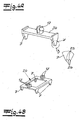
- FIG. 2 shows a formwork device 11 for the production of a component according to the invention.
- Receiving rails 5 were inserted into this formwork device 11 and the pipe 3 was inserted or snapped into place in the pipe receivers 4 of the receiving rails 5.
- the reinforcement elements 9 and the concrete 1 are in the state of Fig. 2 not yet applied or introduced.
- Fig. 2 shows that the pipe 3 is preferably and in the exemplary embodiment arranged in the form of a pipe register which has parallel pipe sections 12 and curved pipe sections 13 connecting the parallel pipe sections 12.
- deflection aid devices 14 are indicated for the bent pipe sections 13, but these are not shown in more concrete terms.
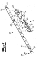
- the Fig. 3 shows a first embodiment of a receiving rail 5 according to the invention.
- the receiving rail 5 is U-shaped in cross section, with a base web 15 forming the U base and two transverse webs 16 arranged perpendicular to the base web 15 forming the U-legs.
- pipe receptacles 4 are provided in each transverse web and a pipe receptacle 4 in one transverse web 16 is aligned with a pipe receptacle 4 in the other transverse web 16, so that an inserted pipe 3 in the area of the pipe receptacles 4 is perpendicular to the longitudinal axis of the receiving rail 5 is arranged.
- Spacers 7 are connected to the underside of the base web 15.
- FIGS Figures 4a and 4b Two embodiments for such spacers 7 are shown in FIGS Figures 4a and 4b shown.
- the spacers 7 are connected to latching elements 17. These latching elements 17 can be latched with the receiving rail 5 in latching openings 18 present in the base web 15.
- the already locked state is in the lower rail section 19 in FIG Fig. 3 shown.
- the receiving rail 5 is in the embodiment according to Fig. 3 composed of two rail sections 19, 20 which can be connected to one another via connecting elements 21. It is also within the scope of the invention that a receiving rail 5 can be composed of more than two rail sections 19, 20.
- reinforcing ribs 22 are connected to the transverse webs 16 in the region of the pipe receptacles 4.
- the sections of the transverse webs 16 between the pipe receptacles 4 are expediently used to support reinforcement elements 9 or to support a reinforcement mat 10.
- these sections of the transverse webs 16 have openings 23 that promote the flow of concrete.
- the spacers 7 are connected to one another via bridge elements 24, and the latching elements 17 are arranged on these bridge elements 24.
- the spacers 7 preferably taper downwards in the exemplary embodiment.
- the spacers are expediently provided with recesses 25 at their tip or at their lower end, so that only point-like or line-like end sections 26 of the spacers 7 are visible on the front surface 2.
- the spacers 7 are integrally formed on the receiving rail 5.
- the spacers 7 are formed on the transverse webs 16 below the pipe receptacles 4.
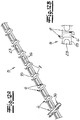
- FIG. 6 Another embodiment of the invention shows Fig. 6 .
- the receiving rails 5 are here per se as in the embodiment of FIG Fig. 3 educated.
- the spacers 7 are arranged on separate spacer rails 27 or are formed in one piece.
- the spacer rails 27 are laid below the receiving rails 5 transversely to the receiving rails 5. It is within the scope of the invention that the spacer rails 27 are connected in the intersection areas with the receiving rail 5 via coupling elements not shown in detail.
- the one in the Fig. 7 The illustrated embodiment is similar to the embodiment according to Fig. 6 .
- spacer rails 27 are used.
- the spacer rails 27 are laid below the receiving rails 5, specifically parallel to the receiving rails 5.
- the receiving rails 5 can be connected to the spacer rails 27 by connecting elements not shown in detail.
- FIG. 8a and 8b Another embodiment of a receiving rail 5 according to the invention is shown.
- a base web 15 is provided here and, in this case, only a single transverse web 16 is arranged perpendicular to this base web 15.
- the pipe receptacles 4 are provided.
- Downwardly directed spacers 7 are integrally formed on both sides of the base web 15.
- Reinforcing ribs 22 are moreover connected on each side of the transverse web 16.
- Fig. 9 shows an embodiment in which the receiving rail 5 as in the embodiment according to Figures 8a and 8b is designed.
- the tubes 3 received in the tube receptacles 4 are fixed with an additional fixing comb 28.
- the fixing comb 28 has receiving openings 29 for the tubes 3, which are arranged at a distance from the tube receivers 4.
- the fixing comb 28 is then slipped over the pipes 3 received in the pipe receptacles 4, so that the pipes 3 are clasped by the fixing comb 28 from above.
- the fixing comb 28 also has two comb sections 30, 31 which can be connected to one another and which can be connected to one another via connecting elements 21.
- the Figures 10a and 10b show a similar receiving rail 5 as that Figures 8a and 8b .
- the Figures 10a, b is the only transverse web 16 in contrast to the embodiment according to the Figures 8a and 8b not arranged centrally on the base web 15 but on one side of the base web 15.
- the Figure 10b shows, that Reinforcing ribs 22 are connected to the transverse web 16 on both sides of the transverse web 16.
- FIG. 11 Another embodiment of a receiving rail 5 according to the invention is shown in FIG Fig. 11 shown.
- the receiving rail 5 is again U-shaped.
- the base web 15 is oriented upwards and the spacers 7 are connected in one piece to the transverse webs 16 oriented downwards or towards the front surface 2.
- the pipe receptacles 4 are in turn provided in these transverse webs 16.
- FIG. 11 FIG. 12 also shows a connection element 32 which can be latched in a latching opening 18 of the base web 15 and can be connected to a reinforcing bar (not shown) with a clamp element 33.
- FIG. 12a The illustrated embodiment for a receiving rail according to the invention is similar to the embodiment according to Fig. 11 .
- additional locking lugs 6 are provided on the tube mounts.
- the locking lugs 6 are arranged diagonally offset to one another ( Figure 12b ) and enable a functionally reliable locking of the tube 3 in the tube receptacles 4.
- FIG. 12a it is also shown that, in addition, half-shell-shaped pipe support elements 34 can be inserted into the pipe receptacles 4. With the help of these pipe support elements 34, the pipe 3 received in the pipe receptacles 4 is additionally protected, in particular, against loads, for example by heavy reinforcement elements 9.
- a further embodiment of a receiving rail 5 is shown.
- This receiving rail 5 is preferably produced by injection molding.
- Two pipe clamps 36 for additional fixing of a pipe 3 are arranged between two aligned pipe receptacles 4.
- a transverse web (not shown) can optionally be provided between two pipe clamps 36, which, however, can easily be removed again if necessary so that the pipe receptacle 4 in question is available for a pipe 3 .
- Securing elements 38 projecting from the upper side of the receiving rail 5 and with bevels pointing away from the tube receivers 4 are provided on the side of the pipe receptacles 4. With the aid of these securing elements 38, it is ensured that reinforcing elements 9 resting on the receiving rail 5 cannot slip into the pipe receptacles 4.
Landscapes
- Engineering & Computer Science (AREA)
- Architecture (AREA)
- Physics & Mathematics (AREA)
- Electromagnetism (AREA)
- Civil Engineering (AREA)
- Structural Engineering (AREA)
- Forms Removed On Construction Sites Or Auxiliary Members Thereof (AREA)
- Manufacturing Of Tubular Articles Or Embedded Moulded Articles (AREA)
- Building Environments (AREA)
Claims (13)
- Élément de construction, de préférence un élément de construction plat, en particulier un élément de plafond ou un élément de plancher plat, l'élément de construction comportant au moins une couche plate constituée à partir d'une masse de scellement durcie, en particulier de béton (1),
dans lequel, au moins un conduit de chauffage et/ou un conduit de refroidissement est enrobé dans la région de la surface avant (2) de l'élément de construction, pour le passage d'un fluide dans la masse de scellement durcie, dans lequel l'au moins un conduit (3) est accueilli dans des admissions de conduit (4) prévues dans une pluralité de rails d'admission, en particulier dans des rails d'admission linéaires (5),
dans lequel un rail d'admission (5) comporte une pluralité de ces admissions de conduit (4), dans lequel au moins un espaceur (7) est rattaché à un rail d'admission (5), définissant l'espacement a entre l'au moins un conduit (3) et la surface avant (2) de l'élément de construction, et dans lequel une couche de surface (8) constituée de la masse de scellement durcie est agencée entre l'au moins un conduit (3) et la surface avant (2),
et dans lequel un rail d'admission (5) comporte au moins une âme de base (15), caractérisé par au moins une âme transversale (16) connectée à l'âme de base (15) et agencée transversalement à l'âme de base (15), et dans lequel une pluralité d'admissions de conduit (4) est prévue dans l'au moins une âme transversale (16), dans lequel le rail d'admission (5) présente uniquement des admissions de conduit (4) conçues ouvertes vers le côté arrière de l'élément de construction, pour l'introduction de conduits (3), dans lequel le rail d'admission (5) est conçu d'une seule pièce,
caractérisé en ce que
au moins un élément d'armature (9) s'applique sur le côté supérieur ou le bord supérieur du rail d'admission (5). - Élément de construction selon la revendication 1, dans lequel l'espacement a entre l'au moins un conduit (3) et la surface avant (2) mesure 3 à 18% de l'épaisseur D de l'élément de construction, de préférence 5 à 14%, et mieux, 6 à 12%.
- Élément de construction selon l'une des revendications 1 ou 2, dans lequel le rapport D/d*a (d : diamètre extérieur du conduit) est compris entre 0,3 et 1,7, de préférence entre 0,4 et 1,5, et mieux, entre 0,5 et 1,3.
- Élément de construction selon l'une des revendications 1 à 3, dans lequel le rapport (A/D) entre l'espacement A entre la surface supérieure ou l'arête avant des rails d'admission (5) et la surface avant (2) de l'élément de construction, et l'épaisseur D de l'élément de construction est compris entre 0,1 et 0,3, de préférence entre 0,12 et 0,25, et mieux, entre 0,13 et 0,21.
- Élément de construction selon l'une des revendications 1 à 4, dans lequel une admission de conduit (4) prévue dans un rail d'admission (5) est conçue ouverte d'un côté, pour l'introduction d'un conduit (3), et dans lequel une admission de conduit (4) est conçue pour l'admission d'un conduit (3) par complémentarité de forme.
- Élément de construction selon l'une des revendications 1 à 5, dans lequel un rail d'admission (5) présente une section transversale en forme de U, dans lequel deux âmes transversales (16) sont agencées transversalement à l'âme de base (15), et dans lequel les admissions de conduit (4) sont prévues dans les deux âmes transversales (16).
- Élément de construction selon l'une des revendications 1 à 6, dans lequel un rail d'admission (5) comporte une pluralité d'espaceurs (7) rattachés à l'âme de base (15) et/ou aux âmes transversales (16).
- Élément de construction selon l'une des revendications 1 à 7, dans lequel une pluralité d'espaceurs (7) est formée en une seule pièce sur un rail d'admission (5).
- Élément de construction selon l'une des revendications 1 à 8, dans lequel une pluralité d'espaceurs (7) est fixée à un rail d'admission (5), par des moyens d'assemblage par enclenchement, en particulier des moyens d'assemblage par enclenchement détachables.
- Élément de construction selon l'une des revendications 1 à 9, dans lequel un espaceur (7) se rétrécit en direction de la surface avant (2) de l'élément de construction, en formant en particulier une pointe en direction de la surface avant (2).
- Élément de construction selon l'une des revendications 1 à 10, dans lequel au moins une partie des espaceurs (7) est fixée à un rail d'admission, sous les admissions de conduit (4).
- Élément de construction selon l'une des revendications 1 à 11, dans lequel une pluralité de percées (23) est incorporée dans un rail d'admission (5), en particulier dans l'âme de base (15) et/ou dans l'au moins une âme transversale (16) d'un rail d'admission (5), pour accueillir la masse de scellement.
- Procédé pour la fabrication d'un élément de construction, en particulier selon l'une des revendications 1 à 12, dans lequel une pluralité de rails d'admission (5) est posée sur le fond d'un coffrage (11), avec des admissions de conduit (4), de manière à ce que des espaceurs (7) fixés aux rails d'admission (5) reposent sur le fond,
dans lequel les rails d'admission (5) comportent respectivement une âme de base (15), caractérisé en ce qu'ils comportent au moins une âme transversale (16) fixée à l'âme de base (15) et agencée transversalement à l'âme de base (15), et dans lequel une pluralité d'admissions de conduit (4) est prévue dans l'au moins une âme transversale (16), dans lequel le rail d'admission (5) est conçu d'une seule pièce,
dans lequel au moins un conduit de chauffage et/ou un conduit de refroidissement est inséré dans les admissions de conduit (4) des rails d'admission (5), dans lequel au moins un élément d'armature est agencé au-dessus des rails d'admission (5),
et dans lequel une masse de scellement est introduite dans le coffrage (11) de manière à ce que les rails d'admission (5) et l'au moins un conduit (3) soient enrobés dans la masse de scellement, au moins sur une partie de leur hauteur, dans lequel le rail d'admission (5) présente uniquement des admissions de conduit (4) conçues ouvertes vers le côté arrière de l'élément de construction, pour l'introduction de conduits (3),
caractérisé en ce que
au moins un élément d'armature (9) s'applique sur le côté supérieur ou le bord supérieur du rail d'admission (5).
Priority Applications (2)
| Application Number | Priority Date | Filing Date | Title |
|---|---|---|---|
| EP10195797.5A EP2466028B2 (fr) | 2010-12-17 | 2010-12-17 | Composant avec des tuyeaux et procédé de fabrication d'un composant |
| DE202011000235U DE202011000235U1 (de) | 2010-12-17 | 2011-02-01 | Bauelement |
Applications Claiming Priority (1)
| Application Number | Priority Date | Filing Date | Title |
|---|---|---|---|
| EP10195797.5A EP2466028B2 (fr) | 2010-12-17 | 2010-12-17 | Composant avec des tuyeaux et procédé de fabrication d'un composant |
Publications (3)
| Publication Number | Publication Date |
|---|---|
| EP2466028A1 EP2466028A1 (fr) | 2012-06-20 |
| EP2466028B1 EP2466028B1 (fr) | 2012-12-19 |
| EP2466028B2 true EP2466028B2 (fr) | 2021-08-11 |
Family
ID=44170521
Family Applications (1)
| Application Number | Title | Priority Date | Filing Date |
|---|---|---|---|
| EP10195797.5A Active EP2466028B2 (fr) | 2010-12-17 | 2010-12-17 | Composant avec des tuyeaux et procédé de fabrication d'un composant |
Country Status (2)
| Country | Link |
|---|---|
| EP (1) | EP2466028B2 (fr) |
| DE (1) | DE202011000235U1 (fr) |
Cited By (1)
| Publication number | Priority date | Publication date | Assignee | Title |
|---|---|---|---|---|
| EP4588587A1 (fr) * | 2024-01-22 | 2025-07-23 | Progress Maschinen & Automation AG | Dispositif de cintrage pour le cintrage automatique d'un tube de climatisation |
Families Citing this family (6)
| Publication number | Priority date | Publication date | Assignee | Title |
|---|---|---|---|---|
| DE202011052248U1 (de) * | 2011-12-09 | 2013-03-13 | Rehau Ag + Co. | Betonkerntemperierungselement sowie Betonkerntemperierungssystem, das ein derartiges Betonkerntemperierungselement umfasst |
| AT513069B1 (de) * | 2012-06-27 | 2014-08-15 | Ke Kelit Kunststoffwerk Gmbh | Vorrichtung zum Klimatisieren eines Raumes |
| CN105133784B (zh) * | 2015-07-31 | 2018-01-12 | 仲杨建筑技术咨询(北京)有限公司 | 双平行式辐射管墙面预制叠合板及其成型方法 |
| CN105672565A (zh) * | 2015-07-31 | 2016-06-15 | 仲杨建筑技术咨询(北京)有限公司 | 辐射管墙面预制叠合板及其成型方法 |
| AT17644U1 (de) * | 2021-04-20 | 2022-10-15 | Ke Kelit Gmbh | Halteschiene für Flächenheizungsrohre |
| AT528124B1 (de) * | 2025-01-20 | 2025-10-15 | Ke Kelit Gmbh | Vorrichtung zum Erkennen der Lage von Flächenheizungsrohren in einer Betonvergussmasse |
Citations (2)
| Publication number | Priority date | Publication date | Assignee | Title |
|---|---|---|---|---|
| EP1207354A2 (fr) † | 2000-11-17 | 2002-05-22 | Josef Steiner | Barre de support, registre de chauffage ou de réfrigération et élément de construction plat de matière susceptible de durcir |
| AT502685B1 (de) † | 2005-11-16 | 2007-05-15 | Wavin Bv | Deckensystem zur aufnahme von kühl- oder heizrohren |
Family Cites Families (3)
| Publication number | Priority date | Publication date | Assignee | Title |
|---|---|---|---|---|
| US4037375A (en) * | 1975-08-18 | 1977-07-26 | Theodore Maggos | Multi-story floor-ceiling system and method |
| DE102004035580A1 (de) * | 2004-07-22 | 2006-02-16 | Rehau Ag + Co. | Verfahren zur Herstellung eines vorgefertigten mit Stabstahl bewehrten Bauelements, insbesondere eines Decken- oder Wandelements, mit wenigstens einer Rohrleitung zur Raumtemperierung und Halteschiene zur Verwendung bei diesem Verfahren |
| EP2213808B1 (fr) * | 2009-01-29 | 2012-01-18 | Ziegelwerk Otto Staudacher GmbH & Co. KG | Produit semi-fini et son procédé de fabrication |
-
2010
- 2010-12-17 EP EP10195797.5A patent/EP2466028B2/fr active Active
-
2011
- 2011-02-01 DE DE202011000235U patent/DE202011000235U1/de not_active Expired - Lifetime
Patent Citations (2)
| Publication number | Priority date | Publication date | Assignee | Title |
|---|---|---|---|---|
| EP1207354A2 (fr) † | 2000-11-17 | 2002-05-22 | Josef Steiner | Barre de support, registre de chauffage ou de réfrigération et élément de construction plat de matière susceptible de durcir |
| AT502685B1 (de) † | 2005-11-16 | 2007-05-15 | Wavin Bv | Deckensystem zur aufnahme von kühl- oder heizrohren |
Cited By (1)
| Publication number | Priority date | Publication date | Assignee | Title |
|---|---|---|---|---|
| EP4588587A1 (fr) * | 2024-01-22 | 2025-07-23 | Progress Maschinen & Automation AG | Dispositif de cintrage pour le cintrage automatique d'un tube de climatisation |
Also Published As
| Publication number | Publication date |
|---|---|
| DE202011000235U1 (de) | 2011-10-24 |
| EP2466028B1 (fr) | 2012-12-19 |
| EP2466028A1 (fr) | 2012-06-20 |
Similar Documents
| Publication | Publication Date | Title |
|---|---|---|
| EP2466028B2 (fr) | Composant avec des tuyeaux et procédé de fabrication d'un composant | |
| EP2839089B1 (fr) | Élément de construction et procédé de fabrication d'un élément de construction | |
| AT513069B1 (de) | Vorrichtung zum Klimatisieren eines Raumes | |
| DE102011088456A1 (de) | Positionierungselement und Anordnung zum Positionieren zumindest eines stabförmigen Bewehrungselementes | |
| DE102007055134A1 (de) | Baufertigelement mit Kühl-/Heizfunktion sowie Decken-Kühl-/Heizsystem | |
| AT414000B (de) | Auflageleiste, heiz- bzw. kühlregister sowie flächiger bauteil aus aushärtbarem werkstoff | |
| DE202021106881U1 (de) | Halteschiene | |
| DE202005022116U1 (de) | Vorgefertigtes Temperierungsmodul für die Verwendung in einem Bauelement, insbesondere einem Decken- oder Wandelement | |
| EP1619005B1 (fr) | Procédé de fabrication d'un mur ou plafond préfabriqué renforcé avec des barres en acier et rail de support utilisé dans un tel procédé | |
| DE102009000612A1 (de) | Wärmetauschervorrichtung zum Austausch von Wärme mit Feststoffen oder Feststoffgemischen | |
| DE202011110605U1 (de) | Schalungsanordnung | |
| DE10259961B4 (de) | Vorgefertigtes Bauelement, insbesondere Decken- oder Wandbauelement aus einem ausgehärteten Material | |
| DE102011114684B4 (de) | Rohrträger für ein Flächentemperiersystem in Betonböden, -wänden und -decken | |
| DE102004034707A1 (de) | Betonkerntemperierungsmodul sowie Herstellungsverfahren für ein Betonkerntemperierungsmodul | |
| EP1972734A1 (fr) | Corps de fixation pour un panneau isolant | |
| WO1998005905A1 (fr) | Panneau de chauffage ou de refroidissement a tubes capillaires pourvu d'une mince couche de couverture en ciment | |
| EP1610064B1 (fr) | Module de conditionnement d'un élément de construction en béton et procédé de fabrication d'un module de conditionnement d'un élément de construction en béton | |
| DE10253867B4 (de) | Vorrichtung zum Austausch von Wärme und/oder Kälte mit Feststoffen oder Feststoffgemischen | |
| DE202024107504U1 (de) | Halteschiene zur Aufnahme von Abschnitten einer Rohrleitung sowie diese umfassendes eines Betonkerntemperierungselement | |
| DE202004015984U1 (de) | Gittermatte und Fertigelementdecke mit einer Gittermatte | |
| DE102012219997A1 (de) | Abstandshalteranordnung | |
| DE102020117356B3 (de) | Elementesatz zur Herstellung eines Streifenfundaments mit wenigstens einer Fundamentecke und Verfahren zur Herstellung einer Schalung für ein Streifenfundament mit wenigstens einer Fundamentecke | |
| EP2019173B1 (fr) | Elément de coffrage pour la construction du type à coffrage perdu tout et coffrage composé de tels éléments de coffrage | |
| DE102004003366B4 (de) | Verfahren zum Herstellen eines Einfamilien-oder Mehrfamilienhauses, Betonfertigteil-Trogplatte für eine Gebäudedecke sowie Fertighaus | |
| EP1959069A1 (fr) | Corps d'isolation sans joint pour une paroi d'extrémité calorifugée et paroi d'extrémité tout comme son procédé de fabrication |
Legal Events
| Date | Code | Title | Description |
|---|---|---|---|
| PUAI | Public reference made under article 153(3) epc to a published international application that has entered the european phase |
Free format text: ORIGINAL CODE: 0009012 |
|
| 17P | Request for examination filed |
Effective date: 20110909 |
|
| AK | Designated contracting states |
Kind code of ref document: A1 Designated state(s): AL AT BE BG CH CY CZ DE DK EE ES FI FR GB GR HR HU IE IS IT LI LT LU LV MC MK MT NL NO PL PT RO RS SE SI SK SM TR |
|
| AX | Request for extension of the european patent |
Extension state: BA ME |
|
| GRAP | Despatch of communication of intention to grant a patent |
Free format text: ORIGINAL CODE: EPIDOSNIGR1 |
|
| RIN1 | Information on inventor provided before grant (corrected) |
Inventor name: DIE ERFINDER HABEN AUF IHRE NENNUNG VERZICHTET. |
|
| GRAS | Grant fee paid |
Free format text: ORIGINAL CODE: EPIDOSNIGR3 |
|
| GRAA | (expected) grant |
Free format text: ORIGINAL CODE: 0009210 |
|
| AK | Designated contracting states |
Kind code of ref document: B1 Designated state(s): AL AT BE BG CH CY CZ DE DK EE ES FI FR GB GR HR HU IE IS IT LI LT LU LV MC MK MT NL NO PL PT RO RS SE SI SK SM TR |
|
| REG | Reference to a national code |
Ref country code: GB Ref legal event code: FG4D Free format text: NOT ENGLISH |
|
| REG | Reference to a national code |
Ref country code: CH Ref legal event code: EP |
|
| REG | Reference to a national code |
Ref country code: AT Ref legal event code: REF Ref document number: 589513 Country of ref document: AT Kind code of ref document: T Effective date: 20130115 |
|
| REG | Reference to a national code |
Ref country code: DE Ref legal event code: R096 Ref document number: 502010001899 Country of ref document: DE Effective date: 20130214 |
|
| REG | Reference to a national code |
Ref country code: NL Ref legal event code: T3 |
|
| PG25 | Lapsed in a contracting state [announced via postgrant information from national office to epo] |
Ref country code: SE Free format text: LAPSE BECAUSE OF FAILURE TO SUBMIT A TRANSLATION OF THE DESCRIPTION OR TO PAY THE FEE WITHIN THE PRESCRIBED TIME-LIMIT Effective date: 20121219 Ref country code: NO Free format text: LAPSE BECAUSE OF FAILURE TO SUBMIT A TRANSLATION OF THE DESCRIPTION OR TO PAY THE FEE WITHIN THE PRESCRIBED TIME-LIMIT Effective date: 20130319 Ref country code: LT Free format text: LAPSE BECAUSE OF FAILURE TO SUBMIT A TRANSLATION OF THE DESCRIPTION OR TO PAY THE FEE WITHIN THE PRESCRIBED TIME-LIMIT Effective date: 20121219 Ref country code: ES Free format text: LAPSE BECAUSE OF FAILURE TO SUBMIT A TRANSLATION OF THE DESCRIPTION OR TO PAY THE FEE WITHIN THE PRESCRIBED TIME-LIMIT Effective date: 20130330 Ref country code: HR Free format text: LAPSE BECAUSE OF FAILURE TO SUBMIT A TRANSLATION OF THE DESCRIPTION OR TO PAY THE FEE WITHIN THE PRESCRIBED TIME-LIMIT Effective date: 20121219 Ref country code: FI Free format text: LAPSE BECAUSE OF FAILURE TO SUBMIT A TRANSLATION OF THE DESCRIPTION OR TO PAY THE FEE WITHIN THE PRESCRIBED TIME-LIMIT Effective date: 20121219 |
|
| REG | Reference to a national code |
Ref country code: LT Ref legal event code: MG4D |
|
| PG25 | Lapsed in a contracting state [announced via postgrant information from national office to epo] |
Ref country code: SI Free format text: LAPSE BECAUSE OF FAILURE TO SUBMIT A TRANSLATION OF THE DESCRIPTION OR TO PAY THE FEE WITHIN THE PRESCRIBED TIME-LIMIT Effective date: 20121219 Ref country code: LV Free format text: LAPSE BECAUSE OF FAILURE TO SUBMIT A TRANSLATION OF THE DESCRIPTION OR TO PAY THE FEE WITHIN THE PRESCRIBED TIME-LIMIT Effective date: 20121219 |
|
| PG25 | Lapsed in a contracting state [announced via postgrant information from national office to epo] |
Ref country code: EE Free format text: LAPSE BECAUSE OF FAILURE TO SUBMIT A TRANSLATION OF THE DESCRIPTION OR TO PAY THE FEE WITHIN THE PRESCRIBED TIME-LIMIT Effective date: 20121219 Ref country code: IS Free format text: LAPSE BECAUSE OF FAILURE TO SUBMIT A TRANSLATION OF THE DESCRIPTION OR TO PAY THE FEE WITHIN THE PRESCRIBED TIME-LIMIT Effective date: 20130419 Ref country code: CZ Free format text: LAPSE BECAUSE OF FAILURE TO SUBMIT A TRANSLATION OF THE DESCRIPTION OR TO PAY THE FEE WITHIN THE PRESCRIBED TIME-LIMIT Effective date: 20121219 Ref country code: SK Free format text: LAPSE BECAUSE OF FAILURE TO SUBMIT A TRANSLATION OF THE DESCRIPTION OR TO PAY THE FEE WITHIN THE PRESCRIBED TIME-LIMIT Effective date: 20121219 Ref country code: RS Free format text: LAPSE BECAUSE OF FAILURE TO SUBMIT A TRANSLATION OF THE DESCRIPTION OR TO PAY THE FEE WITHIN THE PRESCRIBED TIME-LIMIT Effective date: 20121219 Ref country code: BG Free format text: LAPSE BECAUSE OF FAILURE TO SUBMIT A TRANSLATION OF THE DESCRIPTION OR TO PAY THE FEE WITHIN THE PRESCRIBED TIME-LIMIT Effective date: 20130319 |
|
| PG25 | Lapsed in a contracting state [announced via postgrant information from national office to epo] |
Ref country code: PT Free format text: LAPSE BECAUSE OF FAILURE TO SUBMIT A TRANSLATION OF THE DESCRIPTION OR TO PAY THE FEE WITHIN THE PRESCRIBED TIME-LIMIT Effective date: 20130419 Ref country code: PL Free format text: LAPSE BECAUSE OF FAILURE TO SUBMIT A TRANSLATION OF THE DESCRIPTION OR TO PAY THE FEE WITHIN THE PRESCRIBED TIME-LIMIT Effective date: 20121219 Ref country code: RO Free format text: LAPSE BECAUSE OF FAILURE TO SUBMIT A TRANSLATION OF THE DESCRIPTION OR TO PAY THE FEE WITHIN THE PRESCRIBED TIME-LIMIT Effective date: 20121219 |
|
| PLBI | Opposition filed |
Free format text: ORIGINAL CODE: 0009260 |
|
| PLAX | Notice of opposition and request to file observation + time limit sent |
Free format text: ORIGINAL CODE: EPIDOSNOBS2 |
|
| 26 | Opposition filed |
Opponent name: KE KELIT KUNSTSTOFFWERK GESELLSCHAFT M.B.H Effective date: 20130919 |
|
| PG25 | Lapsed in a contracting state [announced via postgrant information from national office to epo] |
Ref country code: DK Free format text: LAPSE BECAUSE OF FAILURE TO SUBMIT A TRANSLATION OF THE DESCRIPTION OR TO PAY THE FEE WITHIN THE PRESCRIBED TIME-LIMIT Effective date: 20121219 |
|
| PG25 | Lapsed in a contracting state [announced via postgrant information from national office to epo] |
Ref country code: CY Free format text: LAPSE BECAUSE OF FAILURE TO SUBMIT A TRANSLATION OF THE DESCRIPTION OR TO PAY THE FEE WITHIN THE PRESCRIBED TIME-LIMIT Effective date: 20121219 |
|
| REG | Reference to a national code |
Ref country code: DE Ref legal event code: R026 Ref document number: 502010001899 Country of ref document: DE Effective date: 20130919 |
|
| PG25 | Lapsed in a contracting state [announced via postgrant information from national office to epo] |
Ref country code: IT Free format text: LAPSE BECAUSE OF FAILURE TO SUBMIT A TRANSLATION OF THE DESCRIPTION OR TO PAY THE FEE WITHIN THE PRESCRIBED TIME-LIMIT Effective date: 20121219 |
|
| PLAF | Information modified related to communication of a notice of opposition and request to file observations + time limit |
Free format text: ORIGINAL CODE: EPIDOSCOBS2 |
|
| PLBB | Reply of patent proprietor to notice(s) of opposition received |
Free format text: ORIGINAL CODE: EPIDOSNOBS3 |
|
| PG25 | Lapsed in a contracting state [announced via postgrant information from national office to epo] |
Ref country code: MC Free format text: LAPSE BECAUSE OF FAILURE TO SUBMIT A TRANSLATION OF THE DESCRIPTION OR TO PAY THE FEE WITHIN THE PRESCRIBED TIME-LIMIT Effective date: 20121219 |
|
| TPAC | Observations filed by third parties |
Free format text: ORIGINAL CODE: EPIDOSNTIPA |
|
| REG | Reference to a national code |
Ref country code: IE Ref legal event code: MM4A |
|
| PG25 | Lapsed in a contracting state [announced via postgrant information from national office to epo] |
Ref country code: IE Free format text: LAPSE BECAUSE OF NON-PAYMENT OF DUE FEES Effective date: 20131217 |
|
| PG25 | Lapsed in a contracting state [announced via postgrant information from national office to epo] |
Ref country code: SM Free format text: LAPSE BECAUSE OF FAILURE TO SUBMIT A TRANSLATION OF THE DESCRIPTION OR TO PAY THE FEE WITHIN THE PRESCRIBED TIME-LIMIT Effective date: 20121219 |
|
| PG25 | Lapsed in a contracting state [announced via postgrant information from national office to epo] |
Ref country code: TR Free format text: LAPSE BECAUSE OF FAILURE TO SUBMIT A TRANSLATION OF THE DESCRIPTION OR TO PAY THE FEE WITHIN THE PRESCRIBED TIME-LIMIT Effective date: 20121219 |
|
| PG25 | Lapsed in a contracting state [announced via postgrant information from national office to epo] |
Ref country code: MK Free format text: LAPSE BECAUSE OF FAILURE TO SUBMIT A TRANSLATION OF THE DESCRIPTION OR TO PAY THE FEE WITHIN THE PRESCRIBED TIME-LIMIT Effective date: 20121219 Ref country code: HU Free format text: LAPSE BECAUSE OF FAILURE TO SUBMIT A TRANSLATION OF THE DESCRIPTION OR TO PAY THE FEE WITHIN THE PRESCRIBED TIME-LIMIT; INVALID AB INITIO Effective date: 20101217 |
|
| REG | Reference to a national code |
Ref country code: CH Ref legal event code: PL |
|
| PG25 | Lapsed in a contracting state [announced via postgrant information from national office to epo] |
Ref country code: MT Free format text: LAPSE BECAUSE OF FAILURE TO SUBMIT A TRANSLATION OF THE DESCRIPTION OR TO PAY THE FEE WITHIN THE PRESCRIBED TIME-LIMIT Effective date: 20121219 Ref country code: GR Free format text: LAPSE BECAUSE OF NON-PAYMENT OF DUE FEES Effective date: 20121219 |
|
| PG25 | Lapsed in a contracting state [announced via postgrant information from national office to epo] |
Ref country code: LI Free format text: LAPSE BECAUSE OF NON-PAYMENT OF DUE FEES Effective date: 20141231 Ref country code: CH Free format text: LAPSE BECAUSE OF NON-PAYMENT OF DUE FEES Effective date: 20141231 |
|
| REG | Reference to a national code |
Ref country code: FR Ref legal event code: PLFP Year of fee payment: 6 |
|
| REG | Reference to a national code |
Ref country code: FR Ref legal event code: PLFP Year of fee payment: 7 |
|
| RDAF | Communication despatched that patent is revoked |
Free format text: ORIGINAL CODE: EPIDOSNREV1 |
|
| STAA | Information on the status of an ep patent application or granted ep patent |
Free format text: STATUS: THE PATENT HAS BEEN GRANTED |
|
| APBM | Appeal reference recorded |
Free format text: ORIGINAL CODE: EPIDOSNREFNO |
|
| APBP | Date of receipt of notice of appeal recorded |
Free format text: ORIGINAL CODE: EPIDOSNNOA2O |
|
| APAH | Appeal reference modified |
Free format text: ORIGINAL CODE: EPIDOSCREFNO |
|
| APBQ | Date of receipt of statement of grounds of appeal recorded |
Free format text: ORIGINAL CODE: EPIDOSNNOA3O |
|
| REG | Reference to a national code |
Ref country code: FR Ref legal event code: PLFP Year of fee payment: 8 |
|
| PGFP | Annual fee paid to national office [announced via postgrant information from national office to epo] |
Ref country code: NL Payment date: 20171219 Year of fee payment: 8 |
|
| PGFP | Annual fee paid to national office [announced via postgrant information from national office to epo] |
Ref country code: GB Payment date: 20171221 Year of fee payment: 8 Ref country code: BE Payment date: 20171219 Year of fee payment: 8 |
|
| PG25 | Lapsed in a contracting state [announced via postgrant information from national office to epo] |
Ref country code: AL Free format text: LAPSE BECAUSE OF FAILURE TO SUBMIT A TRANSLATION OF THE DESCRIPTION OR TO PAY THE FEE WITHIN THE PRESCRIBED TIME-LIMIT Effective date: 20121219 |
|
| REG | Reference to a national code |
Ref country code: NL Ref legal event code: MM Effective date: 20190101 |
|
| GBPC | Gb: european patent ceased through non-payment of renewal fee |
Effective date: 20181217 |
|
| PG25 | Lapsed in a contracting state [announced via postgrant information from national office to epo] |
Ref country code: NL Free format text: LAPSE BECAUSE OF NON-PAYMENT OF DUE FEES Effective date: 20190101 |
|
| REG | Reference to a national code |
Ref country code: BE Ref legal event code: MM Effective date: 20181231 |
|
| PG25 | Lapsed in a contracting state [announced via postgrant information from national office to epo] |
Ref country code: BE Free format text: LAPSE BECAUSE OF NON-PAYMENT OF DUE FEES Effective date: 20181231 |
|
| PG25 | Lapsed in a contracting state [announced via postgrant information from national office to epo] |
Ref country code: GB Free format text: LAPSE BECAUSE OF NON-PAYMENT OF DUE FEES Effective date: 20181217 |
|
| PGFP | Annual fee paid to national office [announced via postgrant information from national office to epo] |
Ref country code: FR Payment date: 20191220 Year of fee payment: 10 |
|
| PLAB | Opposition data, opponent's data or that of the opponent's representative modified |
Free format text: ORIGINAL CODE: 0009299OPPO |
|
| R26 | Opposition filed (corrected) |
Opponent name: KE KELIT GMBH Effective date: 20130919 |
|
| APBU | Appeal procedure closed |
Free format text: ORIGINAL CODE: EPIDOSNNOA9O |
|
| PUAH | Patent maintained in amended form |
Free format text: ORIGINAL CODE: 0009272 |
|
| STAA | Information on the status of an ep patent application or granted ep patent |
Free format text: STATUS: PATENT MAINTAINED AS AMENDED |
|
| 27A | Patent maintained in amended form |
Effective date: 20210811 |
|
| AK | Designated contracting states |
Kind code of ref document: B2 Designated state(s): AL AT BE BG CH CY CZ DE DK EE ES FI FR GB GR HR HU IE IS IT LI LT LU LV MC MK MT NL NO PL PT RO RS SE SI SK SM TR |
|
| REG | Reference to a national code |
Ref country code: DE Ref legal event code: R102 Ref document number: 502010001899 Country of ref document: DE |
|
| PG25 | Lapsed in a contracting state [announced via postgrant information from national office to epo] |
Ref country code: FR Free format text: LAPSE BECAUSE OF NON-PAYMENT OF DUE FEES Effective date: 20201231 |
|
| PGFP | Annual fee paid to national office [announced via postgrant information from national office to epo] |
Ref country code: LU Payment date: 20211222 Year of fee payment: 12 |
|
| PG25 | Lapsed in a contracting state [announced via postgrant information from national office to epo] |
Ref country code: LU Free format text: LAPSE BECAUSE OF NON-PAYMENT OF DUE FEES Effective date: 20221217 |
|
| PGFP | Annual fee paid to national office [announced via postgrant information from national office to epo] |
Ref country code: DE Payment date: 20251120 Year of fee payment: 16 |
|
| REG | Reference to a national code |
Ref country code: DE Ref legal event code: R081 Ref document number: 502010001899 Country of ref document: DE Owner name: KE KELIT GMBH, AT Free format text: FORMER OWNERS: GEBR. LOTTER KG, 71636 LUDWIGSBURG, DE; ROTH WERKE GMBH, 35232 DAUTPHETAL, DE |
|
| PGFP | Annual fee paid to national office [announced via postgrant information from national office to epo] |
Ref country code: AT Payment date: 20251222 Year of fee payment: 16 |
|
| REG | Reference to a national code |
Ref country code: AT Ref legal event code: PC Ref document number: 589513 Country of ref document: AT Kind code of ref document: T Owner name: KE KELIT GMBH, AT Effective date: 20260223 |