EP2466070A2 - Procédé de réparation d'une pièce de transition d'un moteur de turbine à gaz - Google Patents
Procédé de réparation d'une pièce de transition d'un moteur de turbine à gaz Download PDFInfo
- Publication number
- EP2466070A2 EP2466070A2 EP20110192926 EP11192926A EP2466070A2 EP 2466070 A2 EP2466070 A2 EP 2466070A2 EP 20110192926 EP20110192926 EP 20110192926 EP 11192926 A EP11192926 A EP 11192926A EP 2466070 A2 EP2466070 A2 EP 2466070A2
- Authority
- EP
- European Patent Office
- Prior art keywords
- transition piece
- gas turbine
- turbine engine
- aft frame
- laser beam
- Prior art date
- Legal status (The legal status is an assumption and is not a legal conclusion. Google has not performed a legal analysis and makes no representation as to the accuracy of the status listed.)
- Withdrawn
Links
Images
Classifications
-
- B—PERFORMING OPERATIONS; TRANSPORTING
- B23—MACHINE TOOLS; METAL-WORKING NOT OTHERWISE PROVIDED FOR
- B23K—SOLDERING OR UNSOLDERING; WELDING; CLADDING OR PLATING BY SOLDERING OR WELDING; CUTTING BY APPLYING HEAT LOCALLY, e.g. FLAME CUTTING; WORKING BY LASER BEAM
- B23K26/00—Working by laser beam, e.g. welding, cutting or boring
- B23K26/34—Laser welding for purposes other than joining
-
- B—PERFORMING OPERATIONS; TRANSPORTING
- B23—MACHINE TOOLS; METAL-WORKING NOT OTHERWISE PROVIDED FOR
- B23K—SOLDERING OR UNSOLDERING; WELDING; CLADDING OR PLATING BY SOLDERING OR WELDING; CUTTING BY APPLYING HEAT LOCALLY, e.g. FLAME CUTTING; WORKING BY LASER BEAM
- B23K26/00—Working by laser beam, e.g. welding, cutting or boring
- B23K26/20—Bonding
- B23K26/32—Bonding taking account of the properties of the material involved
-
- B—PERFORMING OPERATIONS; TRANSPORTING
- B23—MACHINE TOOLS; METAL-WORKING NOT OTHERWISE PROVIDED FOR
- B23K—SOLDERING OR UNSOLDERING; WELDING; CLADDING OR PLATING BY SOLDERING OR WELDING; CUTTING BY APPLYING HEAT LOCALLY, e.g. FLAME CUTTING; WORKING BY LASER BEAM
- B23K26/00—Working by laser beam, e.g. welding, cutting or boring
- B23K26/34—Laser welding for purposes other than joining
- B23K26/342—Build-up welding
-
- B—PERFORMING OPERATIONS; TRANSPORTING
- B23—MACHINE TOOLS; METAL-WORKING NOT OTHERWISE PROVIDED FOR
- B23K—SOLDERING OR UNSOLDERING; WELDING; CLADDING OR PLATING BY SOLDERING OR WELDING; CUTTING BY APPLYING HEAT LOCALLY, e.g. FLAME CUTTING; WORKING BY LASER BEAM
- B23K35/00—Rods, electrodes, materials, or media, for use in soldering, welding, or cutting
- B23K35/22—Rods, electrodes, materials, or media, for use in soldering, welding, or cutting characterised by the composition or nature of the material
- B23K35/24—Selection of soldering or welding materials proper
- B23K35/30—Selection of soldering or welding materials proper with the principal constituent melting at less than 1550°C
- B23K35/3033—Ni as the principal constituent
-
- B—PERFORMING OPERATIONS; TRANSPORTING
- B23—MACHINE TOOLS; METAL-WORKING NOT OTHERWISE PROVIDED FOR
- B23K—SOLDERING OR UNSOLDERING; WELDING; CLADDING OR PLATING BY SOLDERING OR WELDING; CUTTING BY APPLYING HEAT LOCALLY, e.g. FLAME CUTTING; WORKING BY LASER BEAM
- B23K35/00—Rods, electrodes, materials, or media, for use in soldering, welding, or cutting
- B23K35/22—Rods, electrodes, materials, or media, for use in soldering, welding, or cutting characterised by the composition or nature of the material
- B23K35/24—Selection of soldering or welding materials proper
- B23K35/30—Selection of soldering or welding materials proper with the principal constituent melting at less than 1550°C
- B23K35/3033—Ni as the principal constituent
- B23K35/304—Ni as the principal constituent with Cr as the next major constituent
-
- B—PERFORMING OPERATIONS; TRANSPORTING
- B23—MACHINE TOOLS; METAL-WORKING NOT OTHERWISE PROVIDED FOR
- B23P—METAL-WORKING NOT OTHERWISE PROVIDED FOR; COMBINED OPERATIONS; UNIVERSAL MACHINE TOOLS
- B23P6/00—Restoring or reconditioning objects
- B23P6/04—Repairing fractures or cracked metal parts or products, e.g. castings
- B23P6/045—Repairing fractures or cracked metal parts or products, e.g. castings of turbine components, e.g. moving or stationary blades, rotors, etc.
-
- F—MECHANICAL ENGINEERING; LIGHTING; HEATING; WEAPONS; BLASTING
- F01—MACHINES OR ENGINES IN GENERAL; ENGINE PLANTS IN GENERAL; STEAM ENGINES
- F01D—NON-POSITIVE DISPLACEMENT MACHINES OR ENGINES, e.g. STEAM TURBINES
- F01D9/00—Stators
- F01D9/02—Nozzles; Nozzle boxes; Stator blades; Guide conduits, e.g. individual nozzles
- F01D9/023—Transition ducts between combustor cans and first stage of the turbine in gas-turbine engines; their cooling or sealings
-
- B—PERFORMING OPERATIONS; TRANSPORTING
- B23—MACHINE TOOLS; METAL-WORKING NOT OTHERWISE PROVIDED FOR
- B23K—SOLDERING OR UNSOLDERING; WELDING; CLADDING OR PLATING BY SOLDERING OR WELDING; CUTTING BY APPLYING HEAT LOCALLY, e.g. FLAME CUTTING; WORKING BY LASER BEAM
- B23K2101/00—Articles made by soldering, welding or cutting
- B23K2101/001—Turbines
-
- B—PERFORMING OPERATIONS; TRANSPORTING
- B23—MACHINE TOOLS; METAL-WORKING NOT OTHERWISE PROVIDED FOR
- B23K—SOLDERING OR UNSOLDERING; WELDING; CLADDING OR PLATING BY SOLDERING OR WELDING; CUTTING BY APPLYING HEAT LOCALLY, e.g. FLAME CUTTING; WORKING BY LASER BEAM
- B23K2101/00—Articles made by soldering, welding or cutting
- B23K2101/34—Coated articles ; Surface treated articles
-
- B—PERFORMING OPERATIONS; TRANSPORTING
- B23—MACHINE TOOLS; METAL-WORKING NOT OTHERWISE PROVIDED FOR
- B23K—SOLDERING OR UNSOLDERING; WELDING; CLADDING OR PLATING BY SOLDERING OR WELDING; CUTTING BY APPLYING HEAT LOCALLY, e.g. FLAME CUTTING; WORKING BY LASER BEAM
- B23K2103/00—Materials to be soldered, welded or cut
- B23K2103/08—Non-ferrous metals or alloys
-
- B—PERFORMING OPERATIONS; TRANSPORTING
- B23—MACHINE TOOLS; METAL-WORKING NOT OTHERWISE PROVIDED FOR
- B23K—SOLDERING OR UNSOLDERING; WELDING; CLADDING OR PLATING BY SOLDERING OR WELDING; CUTTING BY APPLYING HEAT LOCALLY, e.g. FLAME CUTTING; WORKING BY LASER BEAM
- B23K2103/00—Materials to be soldered, welded or cut
- B23K2103/50—Inorganic materials other than metals or composite materials
- B23K2103/52—Ceramics
-
- B—PERFORMING OPERATIONS; TRANSPORTING
- B23—MACHINE TOOLS; METAL-WORKING NOT OTHERWISE PROVIDED FOR
- B23P—METAL-WORKING NOT OTHERWISE PROVIDED FOR; COMBINED OPERATIONS; UNIVERSAL MACHINE TOOLS
- B23P2700/00—Indexing scheme relating to the articles being treated, e.g. manufactured, repaired, assembled, connected or other operations covered in the subgroups
- B23P2700/06—Cooling passages of turbine components, e.g. unblocking or preventing blocking of cooling passages of turbine components
-
- B—PERFORMING OPERATIONS; TRANSPORTING
- B23—MACHINE TOOLS; METAL-WORKING NOT OTHERWISE PROVIDED FOR
- B23P—METAL-WORKING NOT OTHERWISE PROVIDED FOR; COMBINED OPERATIONS; UNIVERSAL MACHINE TOOLS
- B23P2700/00—Indexing scheme relating to the articles being treated, e.g. manufactured, repaired, assembled, connected or other operations covered in the subgroups
- B23P2700/13—Parts of turbine combustion chambers
-
- F—MECHANICAL ENGINEERING; LIGHTING; HEATING; WEAPONS; BLASTING
- F05—INDEXING SCHEMES RELATING TO ENGINES OR PUMPS IN VARIOUS SUBCLASSES OF CLASSES F01-F04
- F05D—INDEXING SCHEME FOR ASPECTS RELATING TO NON-POSITIVE-DISPLACEMENT MACHINES OR ENGINES, GAS-TURBINES OR JET-PROPULSION PLANTS
- F05D2230/00—Manufacture
- F05D2230/10—Manufacture by removing material
-
- F—MECHANICAL ENGINEERING; LIGHTING; HEATING; WEAPONS; BLASTING
- F05—INDEXING SCHEMES RELATING TO ENGINES OR PUMPS IN VARIOUS SUBCLASSES OF CLASSES F01-F04
- F05D—INDEXING SCHEME FOR ASPECTS RELATING TO NON-POSITIVE-DISPLACEMENT MACHINES OR ENGINES, GAS-TURBINES OR JET-PROPULSION PLANTS
- F05D2230/00—Manufacture
- F05D2230/20—Manufacture essentially without removing material
- F05D2230/23—Manufacture essentially without removing material by permanently joining parts together
- F05D2230/232—Manufacture essentially without removing material by permanently joining parts together by welding
- F05D2230/234—Laser welding
-
- F—MECHANICAL ENGINEERING; LIGHTING; HEATING; WEAPONS; BLASTING
- F05—INDEXING SCHEMES RELATING TO ENGINES OR PUMPS IN VARIOUS SUBCLASSES OF CLASSES F01-F04
- F05D—INDEXING SCHEME FOR ASPECTS RELATING TO NON-POSITIVE-DISPLACEMENT MACHINES OR ENGINES, GAS-TURBINES OR JET-PROPULSION PLANTS
- F05D2230/00—Manufacture
- F05D2230/30—Manufacture with deposition of material
-
- F—MECHANICAL ENGINEERING; LIGHTING; HEATING; WEAPONS; BLASTING
- F05—INDEXING SCHEMES RELATING TO ENGINES OR PUMPS IN VARIOUS SUBCLASSES OF CLASSES F01-F04
- F05D—INDEXING SCHEME FOR ASPECTS RELATING TO NON-POSITIVE-DISPLACEMENT MACHINES OR ENGINES, GAS-TURBINES OR JET-PROPULSION PLANTS
- F05D2230/00—Manufacture
- F05D2230/80—Repairing, retrofitting or upgrading methods
-
- Y—GENERAL TAGGING OF NEW TECHNOLOGICAL DEVELOPMENTS; GENERAL TAGGING OF CROSS-SECTIONAL TECHNOLOGIES SPANNING OVER SEVERAL SECTIONS OF THE IPC; TECHNICAL SUBJECTS COVERED BY FORMER USPC CROSS-REFERENCE ART COLLECTIONS [XRACs] AND DIGESTS
- Y02—TECHNOLOGIES OR APPLICATIONS FOR MITIGATION OR ADAPTATION AGAINST CLIMATE CHANGE
- Y02T—CLIMATE CHANGE MITIGATION TECHNOLOGIES RELATED TO TRANSPORTATION
- Y02T50/00—Aeronautics or air transport
- Y02T50/60—Efficient propulsion technologies, e.g. for aircraft
Definitions
- the present invention generally relates to welding methods for repairing components formed of high temperature alloys. More particularly, this invention is directed to a method for weld repairing an air-cooled transition piece of an industrial gas turbine engine, by which filling of cooling holes and spallation of a coating on the transition piece can be avoided.
- Superalloys are widely used to form components of turbomachinery, such as turbine components of industrial and aircraft gas turbine engines. Notable examples include turbine buckets (blades), nozzles (vanes), and combustor components such as liners, heatshields and transition pieces. Superalloy components are often formed by casting, and for some applications are preferably or necessarily fabricated by welding as a result of their complexity. Welding is also widely used as a method for repairing cracks and other surface discontinuities in superalloy components caused by thermal cycling or foreign object damage. Welding of superalloy materials is typically performed with gas tungsten arc welding (GTAW) techniques. A filler is typically used in GTAW repairs, with the choice of filler material typically being a ductile filler or a filler whose chemistry roughly matches the base metal.
- GTAW gas tungsten arc welding
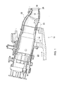
- FIG. 1 schematically represents a cross-sectional view of a single annular combustor assembly of an industrial gas turbine engine 10.
- the combustor assembly is shown having a can-annular combustor 12, which is one of multiple combustors located about the periphery of the turbine engine 10.
- the combustor 12 has a can-type liner 14 whose interior defines a combustion chamber of the turbine 10.
- Multiple fuel nozzle assemblies 16 are located at the head end of the liner 14, while the aft end of the liner 14 is coupled to a transition piece 18. Hot combustion gases from the combustor 12 are conducted to the turbine section (not shown) of the engine through corresponding transition pieces 18.
- the combustors 12 and transition pieces 18 are disposed in a plenum 20 through which bleed air flows from the compressor section (not shown) of the engine 10.
- An impingement jacket (sleeve) 22 is represented as surrounding the transition piece 18, and bleed air 24 within the plenum 20 flows through the jacket 22 to impingement cool the outer surface of the transition piece 18.
- the transition piece 18 is equipped with a flange or frame 26 at its aft end, by which the transition piece 18 is connected to the turbine section.
- the aft frame 26 may also be cooled with bleed air, for example, by controlled bleed air leakage through a seal between mating seal lands of the frame 26 and turbine section, and/or cooling holes (not shown) that define openings at the seal land 28 of the frame 26 to allow bleed air to flow between the jacket 22 and transition piece 18 and then proceed through the frame 26 into a first stage nozzle section within the turbine section of the engine.
- the frame 26 may be fabricated as a separate piece, and then subsequently welded to the aft end of the transition piece 18.
- TBC thermal barrier coating
- YSZ yttria-stabilized zirconia
- PVD physical vapor deposition
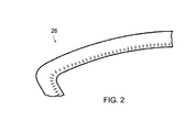
- the aft frame 26 is subject to damage resulting from the combination of high temperatures and stresses that can lead to distortion and fatigue. Because the cooling holes act as stress concentrators, the material of the frame 26 surrounding the holes can be particularly susceptible to cracking due to thermo-mechanical fatigue (TMF). Close spacing between holes and small diameters of the holes (typically about 0.020 to about 0.080 inch (about 0.5 to about 2.0 mm)) tend to aggravate the cracking tendency. Steep temperature gradients are another factor that promotes cracking. The result is that multiple cracks may propagate from individual cooling holes, as seen in FIGS. 2 and 3 , which show a transition piece that has seen service in an industrial gas turbine engine.
- TMF thermo-mechanical fatigue
- the cooling holes must be re-drilled, an arduous and challenging task due to distortion of the transition piece 18 and its frame 26 during service.
- the TBC is reapplied and the transition piece 18 undergoes a heat treatment to relieve stresses induced by the welding operation prior to reassembly with the impingement jacket 22.
- An alternative repair method is to cut the entire aft frame 26 from the transition piece 18 and replace it with a new frame, avoiding the need to repair the cooling holes.
- the present invention resides in a method for weld repairing an air-cooled aft frame of a transition piece of an industrial gas turbine engine, by which filling of cooling holes and spallation of a TBC on the transition piece can be substantially avoided.
- the transition piece has an exterior surface, an interior surface coated with a ceramic coating, and an aft frame adapted for attachment to a turbine section of the gas turbine engine.
- the aft frame has a surface with cooling holes therein and from which cracks have propagated.
- the method includes removing the transition piece from the gas turbine engine and, without removing the ceramic coating or the aft frame from the transition piece, weld repairing the cracks in the aft frame by performing a laser beam welding technique on the surface of the aft frame.
- the laser beam welding technique deposits a filler material on the surface but does not close the cooling holes in the surface or melt or spall the ceramic coating.
- the surface of the aft frame is then machined to remove excess filler material, after which the transition piece can be reinstalled in a gas turbine engine.
- the invention also resides in a transition piece repaired by a process comprising the steps described above.
- a technical effect of the invention is the ability to weld repair a transition piece without depositing excess filler material that would require re-drilling the cooling holes. Furthermore, the low heat input of the welding technique is capable of eliminating the need to strip a coating within the transition piece prior to the weld repair, and then heat treat the transition piece following the weld repair.
- an exemplary transition piece 18 has an exterior surface surrounded by an impingement jacket 22 that is attached to the transition piece 18, an interior surface coated with a TBC or other coating system suitable for thermally insulating the interior surfaces of the transition piece 18, and an air-cooled aft frame 26 adapted to attach the transition piece 18 to the first stage of a turbine section of a gas turbine engine.
- transition pieces of interest to the invention may be formed of a variety of materials, particular examples of which include nickel-based alloys such as Nimonic C263, Hastelloy X, Inconel 617 and Udimet 500.
- the invention is directed to performing a weld repair of cracks that have propagated from cooling holes in a seal land 28 of the aft frame 26, for example, as schematically represented in FIG. 2 .
- Typical configurations for the cooling holes include center-to-center spacings of about 1.25 to about 15 millimeters and diameters of about 0.020 to about 0.080 inch (about 0.5 to about 2.0 mm).
- the invention is not limited to transition pieces having the specific configuration shown in FIGS. 1 through 3 , but instead is applicable to other transition pieces adapted for use in a variety of combustor configurations.
- the present invention uses a laser beam welding (LBW) technique.
- LAW laser beam welding
- laser beam welding is a low heat input welding process that is capable of producing crack-free weld joints in a wide variety of materials, including but not limited to alloys used in turbomachinery.
- An advantage of laser beam welding processes is that the high energy density of a laser beam is able to produce deep, narrow welds. Additional advantages associated with laser beam welding include the ability to be performed without a vacuum chamber or radiation shield, which are usually required for electron beam welding, another known low heat input welding process.
- Preferred lasers for use with this invention are believed to include various solid-state YAG lasers.
- a nonlimiting example of a suitable laser beam welder has a mean power capability of about 200 watts and a peak power capability of about nine kilowatts.
- Suitable operating parameters for the laser bean welding process include a power level of about 30 to 70% of peak power, for example, about 2.7 to about 6.3 kilowatts, and a laser spot diameter of about 0.2 to about 1.6 millimeters, more preferably about 0.35 to about 0.75 millimeters.
- Another operating parameter is to use a pulsed mode of operation, for example, a pulse width of about two to fifteen milliseconds and a pulse frequency of about one to about twelve hertz, though it is foreseeable that a continuous operating mode could be used.
- Other operating parameters such as travel speed, can be ascertained without undue experimentation.
- Control of the laser beam can be achieved with any suitable robotic machinery.
- the laser beam welding process can be performed in any suitable atmosphere, for example, an inert shielding gas (for example, argon or helium), active shielding gas, or a combination thereof to form a mixed shielding gas. Consistent with laser beam welding processes and equipment known in the art, the laser beam welding process does not need to be performed in a vacuum or inert atmosphere.
- a filler material is preferably used to perform a weld repair on the seal land of the aft frame in order to maintain the surface conditions of the seal land. Simultaneously, the amount of filler material deposited must be controlled to avoid the deposition of filler material in the cooling holes located in the seal land.
- Suitable filler materials will depend on the particular composition of the aft frame, though notable examples include commercially available alloys such as Nimonic C263 (a precipitation hardenable nickel-chromium-cobalt alloy with an addition of molybdenum for solid-solution strengthening), Haynes 230 (a solid solution-strengthened nickel-base superalloy), IN625 (a solid solution-strengthened nickel-base superalloy), IN617 (a solid solution-strengthened nickel-base superalloy), Hastelloy W (a nickel-molybdenum alloy containing chromium and iron).
- Nimonic C263 a precipitation hardenable nickel-chromium-cobalt alloy with an addition of molybdenum for solid-solution strengthening
- Haynes 230 a solid solution-strengthened nickel-base superalloy
- IN625 a solid solution-strengthened nickel-base superalloy
- IN617 a solid solution-strength
- the seal land and particularly the material on either side of a crack is heated with a laser beam, though not to the extent that a portion of the metal is vaporized to create a cavity ("keyhole") that would require filling. Instead, the laser beam serves to melt the material on either side of a crack, as well as the filler material, which fuse to form a weldment. Following the laser beam welding technique, it may be desirable in some cases to heat treat the weld-repaired transition piece 18.
- transition piece was removed from service in an industrial gas turbine engine, and discovered to have cracks in its aft frame emanating from cooling holes in the seal land of the aft frame.
- the transition piece and the aft frame were formed of Nimonic C263, which has a composition of, by weight, 19-21% chromium, 19-21% cobalt, 5.6-6.1% molybdenum, 1.9-2.4% titanium, 0-0.6% aluminum (2.4-2.8% Al+Ti), 0.04-0.08% carbon, 0-0.6% manganese, 0-0.2% copper, 0-0.005% boron, 0-0.7% iron, 0-0.4% silicon, the balance nickel and incidental impurities.
- the interior surface of the transition piece was protected by a ceramic thermal barrier coating (TBC).
- TBC ceramic thermal barrier coating
- the cooling holes had diameters of about two millimeters, and were spaced about two millimeters apart.
- the cracks extended completely through the section thickness of the aft frame, and were blended out before individually undergoing pulsed laser beam welding using the following parameters: a power level of about 55% of peak power (about 5 kilowatts), a laser spot diameter of about 0.35 millimeter, a pulse width of about 9 milliseconds, a pulse frequency of about 4 hertz, and a travel speed of about 0.5 millimeter per second.
- the filler material was Haynes 230, having a nominal composition of, by weight, about 22.0% chromium, 2.0% molybdenum, 14.0% tungsten 0.3% aluminum, 0.5% manganese, 0.4% silicon, 0.10% carbon, 0.02% lanthanum, the balance (about 57%) nickel and incidental impurities.
- the filler feed rate of about 0.5 millimeter per second.
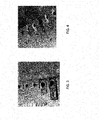
- FIG. 3 Two of the resulting weldments are seen in FIG. 3 , which evidences that a slight build-up of weldment occurred without any significant encroachment into the cooling holes. Furthermore, no melting or spalling of the TBC was observed. Additional cracks were welded in the aft frame in the same manner, after which the seal land was machined by hand blending using an abrasive wheel or belt to remove excess weldment projecting above the surrounding surface of the seal land. The results of this blending operation can be seen in FIG. 4 . From these results, it was concluded that the pulsed laser beam welding technique successfully repaired the cracks without depositing excess filler material that would require re-drilling the cooling holes.
- the low heat input of the welding technique did not melt or spall the TBC, stripping of the TBC prior to the weld repair was unnecessary. It was also concluded that the low heat input of the welding technique would eliminate the need to disassemble the impingement jacket from the transition piece, and eliminate the need to heat treat the transition piece following the weld repair. As such, the weld repair eliminates the need to reapply the TBC and reattach the impingement jacket. Consequently, the laser beam welding process performed on the transition piece was concluded to be less costly and time consuming than prior methods of repairing aft frames of transition pieces.
Landscapes
- Engineering & Computer Science (AREA)
- Mechanical Engineering (AREA)
- Physics & Mathematics (AREA)
- Optics & Photonics (AREA)
- Plasma & Fusion (AREA)
- General Engineering & Computer Science (AREA)
- Laser Beam Processing (AREA)
Applications Claiming Priority (1)
| Application Number | Priority Date | Filing Date | Title |
|---|---|---|---|
| US12/973,170 US20120156020A1 (en) | 2010-12-20 | 2010-12-20 | Method of repairing a transition piece of a gas turbine engine |
Publications (2)
| Publication Number | Publication Date |
|---|---|
| EP2466070A2 true EP2466070A2 (fr) | 2012-06-20 |
| EP2466070A3 EP2466070A3 (fr) | 2015-06-24 |
Family
ID=45318949
Family Applications (1)
| Application Number | Title | Priority Date | Filing Date |
|---|---|---|---|
| EP11192926.1A Withdrawn EP2466070A3 (fr) | 2010-12-20 | 2011-12-12 | Procédé de réparation d'une pièce de transition d'un moteur de turbine à gaz |
Country Status (3)
| Country | Link |
|---|---|
| US (1) | US20120156020A1 (fr) |
| EP (1) | EP2466070A3 (fr) |
| JP (1) | JP2012132445A (fr) |
Cited By (6)
| Publication number | Priority date | Publication date | Assignee | Title |
|---|---|---|---|---|
| US20150217393A1 (en) * | 2014-02-05 | 2015-08-06 | Warren Martin Miglietti | Method of repairing a transition duct side seal |
| EP3064310A1 (fr) * | 2015-03-02 | 2016-09-07 | United Technologies Corporation | Réparation par soudure automatisée des chemises d'une chambre de combustion |
| NO20162002A1 (no) * | 2016-12-15 | 2018-06-18 | Turbine Power Sl | Metode for reparasjon av sprekkskader i stålkonstruksjoner |
| US10443447B2 (en) | 2016-03-14 | 2019-10-15 | General Electric Company | Doubler attachment system |
| FR3088412A1 (fr) * | 2018-11-12 | 2020-05-15 | Safran Aircraft Engines | Chambre de combustion de turbomachine, turbomachine associee |
| CN119260131A (zh) * | 2023-07-06 | 2025-01-07 | 中国科学院金属研究所 | 一种固溶强化型镍基高温合金gh3536带材的真空电子束焊接方法 |
Families Citing this family (51)
| Publication number | Priority date | Publication date | Assignee | Title |
|---|---|---|---|---|
| WO2012129505A1 (fr) * | 2011-03-23 | 2012-09-27 | Scoperta, Inc. | Alliages à base de ni à grains fins pour résistance à la fissuration par corrosion sous tension et procédés pour leur conception |
| CA2861581C (fr) | 2011-12-30 | 2021-05-04 | Scoperta, Inc. | Compositions de revetement |
| US9272365B2 (en) * | 2012-09-12 | 2016-03-01 | Siemens Energy, Inc. | Superalloy laser cladding with surface topology energy transfer compensation |
| MX368291B (es) * | 2012-09-06 | 2019-09-26 | Etxetar Sa | Procedimiento y sistema para el endurecimiento por laser de una superficie de una pieza de trabajo. |
| US9272369B2 (en) | 2012-09-12 | 2016-03-01 | Siemens Energy, Inc. | Method for automated superalloy laser cladding with 3D imaging weld path control |
| US9289854B2 (en) | 2012-09-12 | 2016-03-22 | Siemens Energy, Inc. | Automated superalloy laser cladding with 3D imaging weld path control |
| AU2013329190B2 (en) | 2012-10-11 | 2017-09-28 | Scoperta, Inc. | Non-magnetic metal alloy compositions and applications |
| EP2938836B1 (fr) | 2012-12-29 | 2020-02-05 | United Technologies Corporation | Disque et ensemble de support d'étanchéité |
| WO2014105657A1 (fr) | 2012-12-29 | 2014-07-03 | United Technologies Corporation | Monture à pattes pouvant être infléchies |
| WO2014105599A1 (fr) | 2012-12-29 | 2014-07-03 | United Technologies Corporation | Bouclier thermique pour le refroidissement d'une entretoise |
| DE112013006258B4 (de) | 2012-12-29 | 2026-01-15 | RTX Corporation (n.d.Ges.d. Staates Delaware) | Turbinenrahmenanordnung und Verfahren zum Bereitstellen einer Turbinenrahmenanordnung |
| WO2014105602A1 (fr) | 2012-12-29 | 2014-07-03 | United Technologies Corporation | Bouclier thermique pour carter |
| WO2014105616A1 (fr) | 2012-12-29 | 2014-07-03 | United Technologies Corporation | Architecture de carter de sortie de turbine |
| WO2014105603A1 (fr) | 2012-12-29 | 2014-07-03 | United Technologies Corporation | Bouclier thermique en plusieurs pièces |
| JP6271582B2 (ja) | 2012-12-29 | 2018-01-31 | ユナイテッド テクノロジーズ コーポレイションUnited Technologies Corporation | ガスタービンシールアセンブリおよびシール支持体 |
| US10240532B2 (en) | 2012-12-29 | 2019-03-26 | United Technologies Corporation | Frame junction cooling holes |
| WO2014105619A1 (fr) | 2012-12-29 | 2014-07-03 | United Technologies Corporation | Bossage multifonction pour carter de sortie turbine |
| EP2938868B1 (fr) | 2012-12-29 | 2019-08-07 | United Technologies Corporation | Ensemble de déviation de flux |
| WO2014105800A1 (fr) | 2012-12-29 | 2014-07-03 | United Technologies Corporation | Ensemble d'étanchéité de turbine à gaz et support d'étanchéité |
| US9903224B2 (en) | 2012-12-29 | 2018-02-27 | United Technologies Corporation | Scupper channelling in gas turbine modules |
| EP2938863B1 (fr) | 2012-12-29 | 2019-09-25 | United Technologies Corporation | Liaison mécanique destinée à un écran thermique segmenté |
| US10053998B2 (en) | 2012-12-29 | 2018-08-21 | United Technologies Corporation | Multi-purpose gas turbine seal support and assembly |
| WO2014137444A2 (fr) | 2012-12-29 | 2014-09-12 | United Technologies Corporation | Joint d'étanchéité à doigt à nappes multiples |
| WO2014105604A1 (fr) | 2012-12-29 | 2014-07-03 | United Technologies Corporation | Découpe oblique permettant de diriger une charge de chaleur par rayonnement |
| WO2014105100A1 (fr) | 2012-12-29 | 2014-07-03 | United Technologies Corporation | Pare-chocs pour joints d'étanchéité dans un carter d'échappement de turbine |
| JP6249499B2 (ja) | 2012-12-31 | 2017-12-20 | ユナイテッド テクノロジーズ コーポレイションUnited Technologies Corporation | タービン排気ケースのマルチピース型フレーム |
| WO2014105716A1 (fr) | 2012-12-31 | 2014-07-03 | United Technologies Corporation | Châssis multipièce de boîtier d'échappement de turbine |
| EP2938860B1 (fr) | 2012-12-31 | 2018-08-29 | United Technologies Corporation | Cadre à multiples pièces de compartiment d'échappement de turbine |
| US10330011B2 (en) | 2013-03-11 | 2019-06-25 | United Technologies Corporation | Bench aft sub-assembly for turbine exhaust case fairing |
| US9765623B2 (en) | 2013-07-23 | 2017-09-19 | General Electric Company | Methods for modifying cooling holes with recess-shaped modifications |
| WO2015054637A1 (fr) | 2013-10-10 | 2015-04-16 | Scoperta, Inc. | Procédés de sélection de compositions de matériau et de conception de matériaux ayant une propriété cible |
| US9416667B2 (en) | 2013-11-22 | 2016-08-16 | General Electric Company | Modified turbine components with internally cooled supplemental elements and methods for making the same |
| US9802387B2 (en) | 2013-11-26 | 2017-10-31 | Scoperta, Inc. | Corrosion resistant hardfacing alloy |
| US9909432B2 (en) | 2013-11-26 | 2018-03-06 | General Electric Company | Gas turbine transition piece aft frame assemblies with cooling channels and methods for manufacturing the same |
| CA2951628C (fr) | 2014-06-09 | 2024-03-19 | Scoperta, Inc. | Alliages de rechargement dur resistant aux fissures |
| MY190226A (en) | 2014-07-24 | 2022-04-06 | Oerlikon Metco Us Inc | Hardfacing alloys resistant to hot tearing and cracking |
| CN106661700B (zh) | 2014-07-24 | 2019-05-03 | 思高博塔公司 | 耐冲击的耐磨堆焊和合金及其制备方法 |
| CN107532265B (zh) | 2014-12-16 | 2020-04-21 | 思高博塔公司 | 含多种硬质相的韧性和耐磨铁合金 |
| CN108350528B (zh) | 2015-09-04 | 2020-07-10 | 思高博塔公司 | 无铬和低铬耐磨合金 |
| JP7049244B2 (ja) | 2015-09-08 | 2022-04-06 | エリコン メテコ(ユーエス)インコーポレイテッド | パウダー製造のための非磁性強炭化物形成合金 |
| US20170080530A1 (en) * | 2015-09-22 | 2017-03-23 | Michael Davis McGhee | Method of electron beam welding |
| EP3374536A4 (fr) | 2015-11-10 | 2019-03-20 | Scoperta, Inc. | Matières de projection à l'arc à deux fils à oxydation contrôlée |
| WO2017165546A1 (fr) | 2016-03-22 | 2017-09-28 | Scoperta, Inc. | Revêtement issu de la projection thermique entièrement lisible |
| WO2019006067A1 (fr) * | 2017-06-29 | 2019-01-03 | Siemens Aktiengesellschaft | Procédé de construction d'éléments de refroidissement par impact/effusion dans un composant d'un moteur à turbine à combustion |
| DE102017212575A1 (de) * | 2017-07-21 | 2019-01-24 | Siemens Aktiengesellschaft | Verfahren zur Erhöhung der Leistung einer Gasturbine |
| CA3095046A1 (fr) | 2018-03-29 | 2019-10-03 | Oerlikon Metco (Us) Inc. | Alliages ferreux a teneur reduite en carbures |
| JP7641218B2 (ja) | 2018-10-26 | 2025-03-06 | エリコン メテコ(ユーエス)インコーポレイテッド | 耐食性かつ耐摩耗性のニッケル系合金 |
| CN113631750A (zh) | 2019-03-28 | 2021-11-09 | 欧瑞康美科(美国)公司 | 用于涂布发动机气缸孔的热喷涂铁基合金 |
| EP3962693A1 (fr) | 2019-05-03 | 2022-03-09 | Oerlikon Metco (US) Inc. | Charge d'alimentation pulvérulente destinée au soudage en vrac résistant à l'usure, conçue pour optimiser la facilité de production |
| EP3997252B1 (fr) | 2019-07-09 | 2025-10-29 | Oerlikon Metco (US) Inc. | Alliages à base de fer conçus pour la résistance à l'usure et à la corrosion |
| CN113967820B (zh) * | 2021-11-18 | 2023-11-10 | 华瑞(江苏)燃机服务有限公司 | 一种带冲击冷却套装置过渡段组件的修复方法 |
Family Cites Families (41)
| Publication number | Priority date | Publication date | Assignee | Title |
|---|---|---|---|---|
| US4008844A (en) * | 1975-01-06 | 1977-02-22 | United Technologies Corporation | Method of repairing surface defects using metallic filler material |
| US5783318A (en) * | 1994-06-22 | 1998-07-21 | United Technologies Corporation | Repaired nickel based superalloy |
| US5735044A (en) * | 1995-12-12 | 1998-04-07 | General Electric Company | Laser shock peening for gas turbine engine weld repair |
| US5806751A (en) * | 1996-10-17 | 1998-09-15 | United Technologies Corporation | Method of repairing metallic alloy articles, such as gas turbine engine components |
| US6283356B1 (en) * | 1999-05-28 | 2001-09-04 | General Electric Company | Repair of a recess in an article surface |
| US6158955A (en) * | 1999-06-03 | 2000-12-12 | General Electric Company | Welding method and assembly therefor |
| US6107598A (en) * | 1999-08-10 | 2000-08-22 | Chromalloy Gas Turbine Corporation | Maskant for use during laser welding or drilling |
| JP3846169B2 (ja) * | 2000-09-14 | 2006-11-15 | 株式会社日立製作所 | ガスタービンの補修方法 |
| US6530971B1 (en) * | 2001-01-29 | 2003-03-11 | General Electric Company | Nickel-base braze material and braze repair method |
| US6490791B1 (en) * | 2001-06-22 | 2002-12-10 | United Technologies Corporation | Method for repairing cracks in a turbine blade root trailing edge |
| US7054435B2 (en) * | 2002-04-05 | 2006-05-30 | Avaya Technology Corp. | Apparatus and method for determining a minimal time bound for performing tone detection |
| US6925810B2 (en) * | 2002-11-08 | 2005-08-09 | Honeywell International, Inc. | Gas turbine engine transition liner assembly and repair |
| US7146725B2 (en) * | 2003-05-06 | 2006-12-12 | Siemens Power Generation, Inc. | Repair of combustion turbine components |
| DE10344225A1 (de) * | 2003-09-24 | 2005-04-21 | Mtu Aero Engines Gmbh | Verfahren und Vorrichtung zum Schweißen von Bauteilen |
| US7271894B2 (en) * | 2003-10-01 | 2007-09-18 | General Electric Company | Imaging system for robotically inspecting gas turbine combustion components |
| US20050178750A1 (en) * | 2004-02-13 | 2005-08-18 | Kenny Cheng | Repair of article by laser cladding |
| US20060067830A1 (en) * | 2004-09-29 | 2006-03-30 | Wen Guo | Method to restore an airfoil leading edge |
| US7484651B2 (en) * | 2004-10-22 | 2009-02-03 | Electric Power Research Institute, Inc. | Method to join or repair superalloy hot section turbine components using hot isostatic processing |
| US7587818B2 (en) * | 2004-12-23 | 2009-09-15 | General Electric Company | Repair of gas turbine blade tip without recoating the repaired blade tip |
| US20060231535A1 (en) * | 2005-04-19 | 2006-10-19 | Fuesting Timothy P | Method of welding a gamma-prime precipitate strengthened material |
| US20060260125A1 (en) * | 2005-05-18 | 2006-11-23 | Arnold James E | Method for repairing a gas turbine engine airfoil part using a kinetic metallization process |
| US20070045250A1 (en) * | 2005-08-30 | 2007-03-01 | United Technologies Corporation | Method for manually laser welding metallic parts |
| EP1790745A1 (fr) * | 2005-11-28 | 2007-05-30 | Siemens Aktiengesellschaft | Procédé de réparation de fissures dans des éléments structurels et alliage de brasage pour le brazage des éléments structurels |
| US7653995B2 (en) * | 2006-08-01 | 2010-02-02 | Siemens Energy, Inc. | Weld repair of superalloy materials |
| DE102006044555A1 (de) * | 2006-09-21 | 2008-04-03 | Mtu Aero Engines Gmbh | Reparaturverfahren |
| US8324526B2 (en) * | 2007-02-13 | 2012-12-04 | Siemens Aktiengesellschaft | Welded repair of defects lying on the inside of components |
| US20090113706A1 (en) * | 2007-11-06 | 2009-05-07 | General Electric Company | Craze crack repair of combustor liners |
| DE102008018708A1 (de) * | 2008-04-14 | 2009-10-22 | Fraunhofer-Gesellschaft zur Förderung der angewandten Forschung e.V. | Verfahren zum Schweißen in Abhängigkeit einer Vorzugsrichtung des Substrats |
| US20090320288A1 (en) * | 2008-06-30 | 2009-12-31 | Caterpillar Inc. | Method for repairing a turbine |
| US8105030B2 (en) * | 2008-08-14 | 2012-01-31 | United Technologies Corporation | Cooled airfoils and gas turbine engine systems involving such airfoils |
| US8001793B2 (en) * | 2008-08-29 | 2011-08-23 | Pratt & Whitney Canada Corp. | Gas turbine engine reverse-flow combustor |
| JP2010242610A (ja) * | 2009-04-03 | 2010-10-28 | Toshiba Corp | ガスタービン部品の補修方法、ガスタービン部品及びガスタービン |
| US8373089B2 (en) * | 2009-08-31 | 2013-02-12 | General Electric Company | Combustion cap effusion plate laser weld repair |
| US8196412B2 (en) * | 2009-09-11 | 2012-06-12 | Alstom Technology Ltd | Gas turbine transition duct profile |
| US8444377B2 (en) * | 2009-10-07 | 2013-05-21 | General Electric Company | Method for attaching a connector to deposited material |
| JP5414467B2 (ja) * | 2009-11-09 | 2014-02-12 | キヤノン株式会社 | レーザ加工方法 |
| US8904635B2 (en) * | 2010-11-04 | 2014-12-09 | General Electric Company | Method for servicing a turbine part |
| US8766140B2 (en) * | 2011-10-06 | 2014-07-01 | Lincoln Global, Inc. | Apparatus and method for laser cleaning of coated materials prior to welding |
| EP2591872A1 (fr) * | 2011-11-11 | 2013-05-15 | Siemens Aktiengesellschaft | Procédé de refonte et de remplissage ultérieur et composant obtenu |
| US10016853B2 (en) * | 2013-03-14 | 2018-07-10 | Ansaldo Energia Switzerland AG | Deep trailing edge repair |
| EP2818272B1 (fr) * | 2013-06-28 | 2018-12-26 | TI Automotive (Heidelberg) GmbH | Procédé de soudage évitant des fissures |
-
2010
- 2010-12-20 US US12/973,170 patent/US20120156020A1/en not_active Abandoned
-
2011
- 2011-12-12 EP EP11192926.1A patent/EP2466070A3/fr not_active Withdrawn
- 2011-12-16 JP JP2011275137A patent/JP2012132445A/ja active Pending
Non-Patent Citations (1)
| Title |
|---|
| None |
Cited By (8)
| Publication number | Priority date | Publication date | Assignee | Title |
|---|---|---|---|---|
| US20150217393A1 (en) * | 2014-02-05 | 2015-08-06 | Warren Martin Miglietti | Method of repairing a transition duct side seal |
| US9321115B2 (en) * | 2014-02-05 | 2016-04-26 | Alstom Technologies Ltd | Method of repairing a transition duct side seal |
| EP3064310A1 (fr) * | 2015-03-02 | 2016-09-07 | United Technologies Corporation | Réparation par soudure automatisée des chemises d'une chambre de combustion |
| US10443447B2 (en) | 2016-03-14 | 2019-10-15 | General Electric Company | Doubler attachment system |
| NO20162002A1 (no) * | 2016-12-15 | 2018-06-18 | Turbine Power Sl | Metode for reparasjon av sprekkskader i stålkonstruksjoner |
| NO344485B1 (no) * | 2016-12-15 | 2020-01-13 | Turbine Power Sl | Metode for reparasjon av sprekkskader i stålkonstruksjoner |
| FR3088412A1 (fr) * | 2018-11-12 | 2020-05-15 | Safran Aircraft Engines | Chambre de combustion de turbomachine, turbomachine associee |
| CN119260131A (zh) * | 2023-07-06 | 2025-01-07 | 中国科学院金属研究所 | 一种固溶强化型镍基高温合金gh3536带材的真空电子束焊接方法 |
Also Published As
| Publication number | Publication date |
|---|---|
| US20120156020A1 (en) | 2012-06-21 |
| EP2466070A3 (fr) | 2015-06-24 |
| JP2012132445A (ja) | 2012-07-12 |
Similar Documents
| Publication | Publication Date | Title |
|---|---|---|
| EP2466070A2 (fr) | Procédé de réparation d'une pièce de transition d'un moteur de turbine à gaz | |
| EP2578720B1 (fr) | Procédés de réparation de composants refroidis | |
| US9044825B2 (en) | Method for welding depending on a preferred direction of the substrate | |
| US20050015980A1 (en) | Repair of combustion turbine components | |
| US20090134133A1 (en) | Preheating temperature during welding | |
| US20050120941A1 (en) | Methods for repair of single crystal superalloys by laser welding and products thereof | |
| US20110062220A1 (en) | Superalloy composition and method of forming a turbine engine component | |
| EP3536443B1 (fr) | Formation de rail d'extrémité de pale de turbine | |
| US6468367B1 (en) | Superalloy weld composition and repaired turbine engine component | |
| US8123105B2 (en) | Process for brazing wide gaps | |
| CN102612421B (zh) | 定向结晶材料的单晶焊接 | |
| US20100224600A1 (en) | Two-step welding process | |
| EP1512482B1 (fr) | Méthode pour améliorer la pénétration de soudure par formation d'une couche d'oxyde. | |
| US20100206855A1 (en) | Preheating temperature during remelting | |
| US20190119805A1 (en) | Methods for forming vertically cracked thermal barrier coatings and articles including vertically cracked thermal barrier coatings | |
| US20100237049A1 (en) | Preheating temperature during remelting | |
| KR102829017B1 (ko) | 용접-브레이징 기술 | |
| Miglietti | Wide gap diffusion braze repairs of nozzle segments cast from FSX-414 Co-based superalloy | |
| Miglietti et al. | Repair process technology development and experience for w501f row 1 hot gas path blades | |
| Miglietti et al. | Repair process technology development and experience of frame 7FA+ E, Stage 1 Turbine Buckets | |
| Frederick et al. | Laser Weld Repair of Service Exposed IN738 and GTD111 Buckets |
Legal Events
| Date | Code | Title | Description |
|---|---|---|---|
| PUAI | Public reference made under article 153(3) epc to a published international application that has entered the european phase |
Free format text: ORIGINAL CODE: 0009012 |
|
| AK | Designated contracting states |
Kind code of ref document: A2 Designated state(s): AL AT BE BG CH CY CZ DE DK EE ES FI FR GB GR HR HU IE IS IT LI LT LU LV MC MK MT NL NO PL PT RO RS SE SI SK SM TR |
|
| AX | Request for extension of the european patent |
Extension state: BA ME |
|
| PUAL | Search report despatched |
Free format text: ORIGINAL CODE: 0009013 |
|
| AK | Designated contracting states |
Kind code of ref document: A3 Designated state(s): AL AT BE BG CH CY CZ DE DK EE ES FI FR GB GR HR HU IE IS IT LI LT LU LV MC MK MT NL NO PL PT RO RS SE SI SK SM TR |
|
| AX | Request for extension of the european patent |
Extension state: BA ME |
|
| RIC1 | Information provided on ipc code assigned before grant |
Ipc: B23K 26/34 20140101ALI20150515BHEP Ipc: F01D 5/00 20060101AFI20150515BHEP Ipc: B23P 6/04 20060101ALI20150515BHEP Ipc: F01D 9/02 20060101ALI20150515BHEP Ipc: B23K 26/32 20140101ALI20150515BHEP |
|
| 17P | Request for examination filed |
Effective date: 20160104 |
|
| RBV | Designated contracting states (corrected) |
Designated state(s): AL AT BE BG CH CY CZ DE DK EE ES FI FR GB GR HR HU IE IS IT LI LT LU LV MC MK MT NL NO PL PT RO RS SE SI SK SM TR |
|
| RIC1 | Information provided on ipc code assigned before grant |
Ipc: B23K 26/342 20140101ALI20160129BHEP Ipc: F01D 5/00 20060101AFI20160129BHEP Ipc: B23K 26/32 20140101ALI20160129BHEP Ipc: B23K 26/34 20140101ALI20160129BHEP Ipc: B23K 101/34 20060101ALI20160129BHEP Ipc: B23K 35/30 20060101ALI20160129BHEP Ipc: B23K 101/00 20060101ALI20160129BHEP Ipc: B23P 6/04 20060101ALI20160129BHEP Ipc: B23K 26/322 20140101ALI20160129BHEP Ipc: B23K 103/00 20060101ALI20160129BHEP Ipc: F01D 9/02 20060101ALI20160129BHEP |
|
| GRAP | Despatch of communication of intention to grant a patent |
Free format text: ORIGINAL CODE: EPIDOSNIGR1 |
|
| INTG | Intention to grant announced |
Effective date: 20160404 |
|
| STAA | Information on the status of an ep patent application or granted ep patent |
Free format text: STATUS: THE APPLICATION IS DEEMED TO BE WITHDRAWN |
|
| 18D | Application deemed to be withdrawn |
Effective date: 20160817 |