EP2466072A2 - Axiallüfter zur Luftförderung - Google Patents
Axiallüfter zur Luftförderung Download PDFInfo
- Publication number
- EP2466072A2 EP2466072A2 EP11075270A EP11075270A EP2466072A2 EP 2466072 A2 EP2466072 A2 EP 2466072A2 EP 11075270 A EP11075270 A EP 11075270A EP 11075270 A EP11075270 A EP 11075270A EP 2466072 A2 EP2466072 A2 EP 2466072A2
- Authority
- EP
- European Patent Office
- Prior art keywords
- fan
- plate
- blade
- secured
- fan blade
- Prior art date
- Legal status (The legal status is an assumption and is not a legal conclusion. Google has not performed a legal analysis and makes no representation as to the accuracy of the status listed.)
- Granted
Links
Images

Classifications
-
- F—MECHANICAL ENGINEERING; LIGHTING; HEATING; WEAPONS; BLASTING
- F01—MACHINES OR ENGINES IN GENERAL; ENGINE PLANTS IN GENERAL; STEAM ENGINES
- F01D—NON-POSITIVE DISPLACEMENT MACHINES OR ENGINES, e.g. STEAM TURBINES
- F01D5/00—Blades; Blade-carrying members; Heating, heat-insulating, cooling or antivibration means on the blades or the members
- F01D5/12—Blades
- F01D5/14—Form or construction
- F01D5/16—Form or construction for counteracting blade vibration
-
- F—MECHANICAL ENGINEERING; LIGHTING; HEATING; WEAPONS; BLASTING
- F04—POSITIVE - DISPLACEMENT MACHINES FOR LIQUIDS; PUMPS FOR LIQUIDS OR ELASTIC FLUIDS
- F04D—NON-POSITIVE-DISPLACEMENT PUMPS
- F04D29/00—Details, component parts, or accessories
- F04D29/66—Combating cavitation, whirls, noise, vibration or the like; Balancing
- F04D29/661—Combating cavitation, whirls, noise, vibration or the like; Balancing especially adapted for elastic fluid pumps
- F04D29/668—Combating cavitation, whirls, noise, vibration or the like; Balancing especially adapted for elastic fluid pumps damping or preventing mechanical vibrations
-
- F—MECHANICAL ENGINEERING; LIGHTING; HEATING; WEAPONS; BLASTING
- F04—POSITIVE - DISPLACEMENT MACHINES FOR LIQUIDS; PUMPS FOR LIQUIDS OR ELASTIC FLUIDS
- F04D—NON-POSITIVE-DISPLACEMENT PUMPS
- F04D29/00—Details, component parts, or accessories
- F04D29/26—Rotors specially for elastic fluids
- F04D29/32—Rotors specially for elastic fluids for axial flow pumps
- F04D29/321—Rotors specially for elastic fluids for axial flow pumps for axial flow compressors
- F04D29/324—Blades
-
- F—MECHANICAL ENGINEERING; LIGHTING; HEATING; WEAPONS; BLASTING
- F04—POSITIVE - DISPLACEMENT MACHINES FOR LIQUIDS; PUMPS FOR LIQUIDS OR ELASTIC FLUIDS
- F04D—NON-POSITIVE-DISPLACEMENT PUMPS
- F04D29/00—Details, component parts, or accessories
- F04D29/26—Rotors specially for elastic fluids
- F04D29/32—Rotors specially for elastic fluids for axial flow pumps
- F04D29/38—Blades
- F04D29/388—Blades characterised by construction
Definitions
- the present invention relates to axial air movement fans comprising a plurality of elongate fan blades disposed about a hub so as to extend in a generally radial direction.
- Each fan blade therefore constitutes a cantilever secured to the hub and extending outwardly to the outer free end of the blade.
- the fan blades are elongate and typically placed at an angle to the circumferential plane of the axis of rotation and may have an aerofoil type cross-section to drive air across the fan. In cross-section, the fan blades have a major axis and a minor axis.
- the fan blades In operation, when driving air, the fan blades are subject to air pressure and further forces caused by buffeting and turbulence of the air passing through the faun. These forces are transmitted to the hub as a cyclical bending moment through the root of the fan blade which is secured to the hub. The blades thus tend to bend about the major axis and the stress concentration at this point can lead to cracking and failure of the blade.
- the present invention seeks to provide a solution to this problem.
- an axial air movement fan comprising a hub with a plurality of elongate fan blades extending generally radially outwardly therefrom, wherein each fan blade is at least partially hollow and at least one damping mass is located within the hollow part, the mass being at least partially provided by a resilient plate, one edge of which is secured to the fan blade to form a cantilever, and being secured to the fan blade in such a way as oscillate relative to the fan blade in response to oscillatory flexing of the fan blade in a first plane, thereby to damp the flexing of the fan blade, the end of the plate remote from said secured end being held in a guide device to constrain its movement in a controlled manner when the plate is oscillating, and wherein a further guide device is located between the secured end of the plate and the first guide device and engages the plate in such a way as to enable the natural frequency of oscillation of the mass to be adjusted to match the natural frequency of the blade.
- the plate is constrained against radial movement caused by centrifugal force, but is permitted a degree of lateral resilient movement to enable the plate to oscillate.
- a resilient damping mass is located between each of the two members and the plate.
- the further guide device is located closer to the secured end than the outermost end.
- the cross-sectional area of the plate varies along its length to give a desired form of flexure.
- a plurality of said plates may be provided in each fan blade.
- Figure 1 shows a hub 1 of an axial fan mounted for rotation about an axis 2.
- a plurality of elongate fan blades equidistantly disposed about the periphery of the hub and secured thereto so as to extend in a generally radial direction.
- the fan blade consists of an elongate member extending generally radially and is secured at its root to the hub at a slight angle to the plane of rotation of the hub.
- the fan has in cross-section a major axis 4 and a minor axis 5. It also has a radially extending longitudinal main axis 6.
- the weight of the mass, the resilience of the wire and the initial tension in the wire is calculated to permit the mass to oscillate in response to vibratory movement of the blade at its first natural frequency.
- the fan blade acts as a cantilever and if an exciting force caused by turbulent airflow over the fan blade is present at the first natural frequency of the fan blade, permanent oscillation at the natural frequency may occur and this vibratory movement is opposed and dampened by the corresponding transverse oscillations of the mass, which responds to the oscillation of the fan blade and serves to damp out the induced oscillations in the fan blade. In this way, the stresses in the blade, particularly at the root of the blade, which could lead to early failure of the blade, are substantially reduced.
- the mass it is desirable for the mass to be located as far towards the outer tip of the fan blade as possible as this reduces the size of the mass needed.
- the mass may be supported on a synthetic rubber bushing system designed to restrain the mass against movement in a radial direction but to move in a controlled resilient manner in a direction normal to the major axis of the blade.
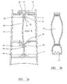
- Figure 3a shows a flexible plate 12 located in the interior of a fan blade casing 13.
- the radially innermost edge 14 of the plate 12 is secured by bolts in a mounting 15 secured to the main body of the fan blade.
- the plate 12 is located in a guide device 17 which has a pair of opposing clamping members 18 and 19 between which the plate is located.
- the locating members are secured by bolts to a mounting bracket 20 secured to the main body of the fan blade13.
- the surfaces 21, 22 of the clamping members facing and engaging with the plate 12 are curved or arcuate so that there is only a single line contact between the clamping members and the plate on a line a short distance from the outer edge 14 of the plate.
- the outer part of the plate 12 is able to pivot slightly when the plate curves due to oscillatory forces and is also able to accommodate the slight change in length, that is longitudinal extent, of the plate due to the curvature it adopts when being deflected.
- resilient means such as rubber bushing is positioned between the surfaces of the clamping members and the plate, the resilient means having sufficient flexibility to accommodate the required slight movement of the end of the plate.
- a further guide 23 may be positioned intermediate the ends of the plate 12 to control the amount of movement of the plate in this mid-position and to fine tune the natural frequency of vibration of the plate to conform to that of the individual blade.
- this further guide' device is located approximately one quarter of the way from the fixed end of the plate towards the free end, but the position at which it engages the plate may be varied to give the oscillatory characteristics desired.
- the further guide device has two clamping members 24, 25 which engage the plate 12 on a line contact. The two clamping members are again bolted to a mount 26 secured to the main body of the fan blade. It is also envisaged that resilient damping means may be disposed between the clamping faces of the members 24 and 25 and the plate 12.
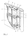
- FIG 4 there is shown a part sectional view of a fan blade 13 having a hollow interior containing two damping plates 12, both in accordance with the present invention.
- the two damping plates 12 are identical and only one will be described for convenience, although it will be appreciated that the two devices may be of different size, thickness and shape to achieve the damping characteristics required.
- the plate 12 is secured in a mounting bracket 15 in turn secured to the main body of the fan blade 13. At its radially outermost end 16, the plate is located in a guide device 17 as described in connection with Figure 3a .
- a further guide 23 is located, although, compared to the embodiment of Figure 3a , the clamping members 24, 25 are directed in the radially outward direction rather than radially inwardly.
- the point at which the clamping members engage the plate is adjustable by means of changing the shape of the members or by spacers positioned between the clamping members and the mounting 24 through which the device is secured to the fan blade. In this way the natural frequency of oscillation can be fine-tuned to match the individual blade.
- a further damping means 27 is located generally intermediate the guide devices 17 and 23.
- the damping means 27 consists of brackets 28, 29 secured to the main body of the fan blade 13 and each carrying a pair of resilient damping masses 31, 32 formed by rubber bushes, which abut the faces of the plate 12 and are designed to limit and damp the oscillatory movement of the plate. Although shown as abutting the plate, it will be understood that in certain circumstances these resilient masses 31, 32 may be spaced from the surface of the plate in the static position.
- the fan blade 13 contains two identical plates 12 but it is envisaged that these plates may differ in size and thickness, and response rate to give the desired damping characteristics.
- the mountings 24 for the plates 12 are located in elongate slots 32 in a subframe 33 which is itself secured to the fan blade. In this way, the whole damping assembly can be built as a subassembly with varying widths of plate for easy incorporation into the fan blade on final assembly.
- the mass may be suspended on the outside of the blade with the wire being secured to limbs extending outwardly from the blade face. It is possible that two masses may be provided, one on each face of the blade. It is also possible for the mass or masses to be secured directly to the blade by means of a resilient mounting bush formed of synthetic rubber.
- a higher frequency harmonic may be generated in the fan blade causing the blades to oscillate about its longitudinal axis 6.
- a smaller mass may be secured in the hollow section of the blade in such a way that it is constrained against radial movement but is able to oscillate about the longitudinal axis 6 of the blade.
- the mass it may be preferable for the mass to be a disc like structure with its mass concentrated at the periphery.
- the mass may be formed by an outer skin section bonded to the rest of the blade by means of a resilient bushing and having the same profile as the fan blade so as not to adversely effect the flow of air past the blade.
Landscapes
- Engineering & Computer Science (AREA)
- Mechanical Engineering (AREA)
- General Engineering & Computer Science (AREA)
- Structures Of Non-Positive Displacement Pumps (AREA)
Applications Claiming Priority (1)
| Application Number | Priority Date | Filing Date | Title |
|---|---|---|---|
| GB1021349.4A GB2486470A (en) | 2010-12-16 | 2010-12-16 | Fan blade with oscillating damping mass |
Publications (3)
| Publication Number | Publication Date |
|---|---|
| EP2466072A2 true EP2466072A2 (de) | 2012-06-20 |
| EP2466072A3 EP2466072A3 (de) | 2016-12-21 |
| EP2466072B1 EP2466072B1 (de) | 2018-07-04 |
Family
ID=43567308
Family Applications (1)
| Application Number | Title | Priority Date | Filing Date |
|---|---|---|---|
| EP11075270.6A Active EP2466072B1 (de) | 2010-12-16 | 2011-12-14 | Axiallüfter zur Luftförderung |
Country Status (2)
| Country | Link |
|---|---|
| EP (1) | EP2466072B1 (de) |
| GB (2) | GB2486470A (de) |
Cited By (2)
| Publication number | Priority date | Publication date | Assignee | Title |
|---|---|---|---|---|
| WO2015112891A1 (en) | 2014-01-24 | 2015-07-30 | United Technologies Corporation | Additive manufacturing process grown integrated torsional damper mechanism in gas turbine engine blade |
| CN112780592A (zh) * | 2021-03-01 | 2021-05-11 | 珠海格力电器股份有限公司 | 一种轴套固线组件及电风扇 |
Families Citing this family (1)
| Publication number | Priority date | Publication date | Assignee | Title |
|---|---|---|---|---|
| US11927137B2 (en) * | 2022-03-21 | 2024-03-12 | Ge Infrastructure Technology Llc | System and method for insulating components in an exhaust gas flow from a gas turbine |
Family Cites Families (11)
| Publication number | Priority date | Publication date | Assignee | Title |
|---|---|---|---|---|
| US2689107A (en) * | 1949-08-13 | 1954-09-14 | United Aircraft Corp | Vibration damper for blades and vanes |
| US2828941A (en) * | 1952-12-24 | 1958-04-01 | United Aircraft Corp | Blade damping means |
| US2920868A (en) * | 1955-10-05 | 1960-01-12 | Westinghouse Electric Corp | Dampened blade structure |
| GB2093126B (en) * | 1981-02-12 | 1984-05-16 | Rolls Royce | Rotor blade for a gas turbine engine |
| US5232344A (en) * | 1992-01-17 | 1993-08-03 | United Technologies Corporation | Internally damped blades |
| DE29522190U1 (de) * | 1994-02-07 | 2000-12-14 | Bonus Energy A/S, Brande | Windmühlenblatt |
| US6155789A (en) * | 1999-04-06 | 2000-12-05 | General Electric Company | Gas turbine engine airfoil damper and method for production |
| JP5046647B2 (ja) * | 2004-10-15 | 2012-10-10 | エドワーズ株式会社 | ダンパおよび真空ポンプ |
| DK1754886T3 (da) * | 2005-08-17 | 2012-12-17 | Gen Electric | Rotorblad til en vindenergiturbine |
| US7270517B2 (en) * | 2005-10-06 | 2007-09-18 | Siemens Power Generation, Inc. | Turbine blade with vibration damper |
| FR2933068B1 (fr) * | 2008-06-27 | 2011-02-25 | Eurocopter France | Pale pour reduire les mouvements en trainee de ladite pale et procede pour reduire un tel mouvement en trainee. |
-
2010
- 2010-12-16 GB GB1021349.4A patent/GB2486470A/en not_active Withdrawn
-
2011
- 2011-12-14 GB GB1121432.7A patent/GB2486557B/en active Active
- 2011-12-14 EP EP11075270.6A patent/EP2466072B1/de active Active
Cited By (4)
| Publication number | Priority date | Publication date | Assignee | Title |
|---|---|---|---|---|
| WO2015112891A1 (en) | 2014-01-24 | 2015-07-30 | United Technologies Corporation | Additive manufacturing process grown integrated torsional damper mechanism in gas turbine engine blade |
| EP3097268A4 (de) * | 2014-01-24 | 2017-03-15 | United Technologies Corporation | Durch additives fertigungsverfahren hergestellter integrierter torsionsschwingungsmechanismus in einer gasturbinenschaufel |
| US10914320B2 (en) | 2014-01-24 | 2021-02-09 | Raytheon Technologies Corporation | Additive manufacturing process grown integrated torsional damper mechanism in gas turbine engine blade |
| CN112780592A (zh) * | 2021-03-01 | 2021-05-11 | 珠海格力电器股份有限公司 | 一种轴套固线组件及电风扇 |
Also Published As
| Publication number | Publication date |
|---|---|
| GB2486557B (en) | 2017-02-08 |
| EP2466072A3 (de) | 2016-12-21 |
| GB2486470A (en) | 2012-06-20 |
| EP2466072B1 (de) | 2018-07-04 |
| GB201121432D0 (en) | 2012-01-25 |
| GB2486557A (en) | 2012-06-20 |
| GB201021349D0 (en) | 2011-01-26 |
Similar Documents
| Publication | Publication Date | Title |
|---|---|---|
| US6009986A (en) | Mass damper | |
| EP1754886B1 (de) | Rotorblatt für eine Windenergieanlage | |
| RU2517643C2 (ru) | Винт вертолета и вертолет (варианты), содержащий этот винт | |
| US5681142A (en) | Damping means for a stator assembly of a gas turbine engine | |
| CN101297112A (zh) | 包括一个或多个振动阻尼器的风轮机叶片 | |
| US20140110892A1 (en) | Motor mounting assembly with tunable vibration and noise reduction capabilities | |
| JPH109341A (ja) | 振動吸収装置 | |
| EP2466072B1 (de) | Axiallüfter zur Luftförderung | |
| EP2146119A1 (de) | Abdichtungsvorrichtung | |
| KR101121126B1 (ko) | 블레이드의 항력 운동을 감소시키기 위한 블레이드 및 항력 운동을 감소시키는 방법 | |
| US6715989B2 (en) | Axial fan | |
| KR101497533B1 (ko) | 진동 감쇄기를 포함하는 헬리콥터 회전기 | |
| US9777594B2 (en) | Energy damping system for gas turbine engine stationary vane | |
| US3027138A (en) | Turbine blades | |
| US20030139217A1 (en) | Shaft damper | |
| KR102618489B1 (ko) | 호버링 가능한 항공기를 위한 로터 및 호버링 가능한 항공기의 로터의 마스트에 전달되는 진동 억제를 위한 방법 | |
| CN107327420B (zh) | 一种能降低散热器风扇电机振动噪音的风扇轮毂 | |
| RU2665191C2 (ru) | Лопасть для промышленного осевого вентилятора и промышленный осевой вентилятор, содержащий такую лопасть | |
| EP3832134A1 (de) | Verdichter mit variabler geschwindigkeit | |
| CN218953591U (zh) | 电机减振结构及风扇 | |
| RU2814339C2 (ru) | Демпфирующее средство электродвигателя устройства для генерирования воздушного потока и указанное устройство, содержащее демпфирующее средство | |
| JP2007064353A (ja) | 揺動型制振装置 | |
| CN114026311A (zh) | 具有阻尼器的涡轮机组件 | |
| EP4707544A1 (de) | Nachgiebige, dämpfende keilhalterung für einen fan-liner | |
| ES2337942T3 (es) | Dispositivo para un rodamiento amortiguador de vibraciones destinado a un motor electrico. |
Legal Events
| Date | Code | Title | Description |
|---|---|---|---|
| PUAI | Public reference made under article 153(3) epc to a published international application that has entered the european phase |
Free format text: ORIGINAL CODE: 0009012 |
|
| AK | Designated contracting states |
Kind code of ref document: A2 Designated state(s): AL AT BE BG CH CY CZ DE DK EE ES FI FR GB GR HR HU IE IS IT LI LT LU LV MC MK MT NL NO PL PT RO RS SE SI SK SM TR |
|
| AX | Request for extension of the european patent |
Extension state: BA ME |
|
| PUAL | Search report despatched |
Free format text: ORIGINAL CODE: 0009013 |
|
| RAP1 | Party data changed (applicant data changed or rights of an application transferred) |
Owner name: HOWDEN AXIAL FANS AB |
|
| AK | Designated contracting states |
Kind code of ref document: A3 Designated state(s): AL AT BE BG CH CY CZ DE DK EE ES FI FR GB GR HR HU IE IS IT LI LT LU LV MC MK MT NL NO PL PT RO RS SE SI SK SM TR |
|
| AX | Request for extension of the european patent |
Extension state: BA ME |
|
| RIC1 | Information provided on ipc code assigned before grant |
Ipc: F03D 11/00 00000000ALI20161116BHEP Ipc: F04D 29/38 20060101ALI20161116BHEP Ipc: F01D 5/16 20060101ALI20161116BHEP Ipc: F04D 19/00 20060101ALI20161116BHEP Ipc: F04D 29/66 20060101ALI20161116BHEP Ipc: F01D 5/26 20060101AFI20161116BHEP Ipc: F04D 29/32 20060101ALI20161116BHEP |
|
| STAA | Information on the status of an ep patent application or granted ep patent |
Free format text: STATUS: THE APPLICATION HAS BEEN PUBLISHED |
|
| STAA | Information on the status of an ep patent application or granted ep patent |
Free format text: STATUS: REQUEST FOR EXAMINATION WAS MADE |
|
| 17P | Request for examination filed |
Effective date: 20170622 |
|
| RBV | Designated contracting states (corrected) |
Designated state(s): AL AT BE BG CH CY CZ DE DK EE ES FI FR GB GR HR HU IE IS IT LI LT LU LV MC MK MT NL NO PL PT RO RS SE SI SK SM TR |
|
| REG | Reference to a national code |
Ref country code: DE Ref legal event code: R079 Ref document number: 602011049679 Country of ref document: DE Free format text: PREVIOUS MAIN CLASS: F01D0005260000 Ipc: F04D0029660000 |
|
| GRAP | Despatch of communication of intention to grant a patent |
Free format text: ORIGINAL CODE: EPIDOSNIGR1 |
|
| STAA | Information on the status of an ep patent application or granted ep patent |
Free format text: STATUS: GRANT OF PATENT IS INTENDED |
|
| RIC1 | Information provided on ipc code assigned before grant |
Ipc: F04D 29/66 20060101AFI20180118BHEP Ipc: F04D 29/38 20060101ALI20180118BHEP Ipc: F04D 19/00 20060101ALI20180118BHEP |
|
| INTG | Intention to grant announced |
Effective date: 20180208 |
|
| GRAS | Grant fee paid |
Free format text: ORIGINAL CODE: EPIDOSNIGR3 |
|
| GRAA | (expected) grant |
Free format text: ORIGINAL CODE: 0009210 |
|
| STAA | Information on the status of an ep patent application or granted ep patent |
Free format text: STATUS: THE PATENT HAS BEEN GRANTED |
|
| AK | Designated contracting states |
Kind code of ref document: B1 Designated state(s): AL AT BE BG CH CY CZ DE DK EE ES FI FR GB GR HR HU IE IS IT LI LT LU LV MC MK MT NL NO PL PT RO RS SE SI SK SM TR |
|
| REG | Reference to a national code |
Ref country code: GB Ref legal event code: FG4D |
|
| REG | Reference to a national code |
Ref country code: CH Ref legal event code: EP |
|
| REG | Reference to a national code |
Ref country code: AT Ref legal event code: REF Ref document number: 1014815 Country of ref document: AT Kind code of ref document: T Effective date: 20180715 |
|
| REG | Reference to a national code |
Ref country code: IE Ref legal event code: FG4D |
|
| REG | Reference to a national code |
Ref country code: DE Ref legal event code: R096 Ref document number: 602011049679 Country of ref document: DE |
|
| REG | Reference to a national code |
Ref country code: NL Ref legal event code: MP Effective date: 20180704 |
|
| REG | Reference to a national code |
Ref country code: LT Ref legal event code: MG4D |
|
| REG | Reference to a national code |
Ref country code: AT Ref legal event code: MK05 Ref document number: 1014815 Country of ref document: AT Kind code of ref document: T Effective date: 20180704 |
|
| PG25 | Lapsed in a contracting state [announced via postgrant information from national office to epo] |
Ref country code: NL Free format text: LAPSE BECAUSE OF FAILURE TO SUBMIT A TRANSLATION OF THE DESCRIPTION OR TO PAY THE FEE WITHIN THE PRESCRIBED TIME-LIMIT Effective date: 20180704 |
|
| PG25 | Lapsed in a contracting state [announced via postgrant information from national office to epo] |
Ref country code: NO Free format text: LAPSE BECAUSE OF FAILURE TO SUBMIT A TRANSLATION OF THE DESCRIPTION OR TO PAY THE FEE WITHIN THE PRESCRIBED TIME-LIMIT Effective date: 20181004 Ref country code: GR Free format text: LAPSE BECAUSE OF FAILURE TO SUBMIT A TRANSLATION OF THE DESCRIPTION OR TO PAY THE FEE WITHIN THE PRESCRIBED TIME-LIMIT Effective date: 20181005 Ref country code: AT Free format text: LAPSE BECAUSE OF FAILURE TO SUBMIT A TRANSLATION OF THE DESCRIPTION OR TO PAY THE FEE WITHIN THE PRESCRIBED TIME-LIMIT Effective date: 20180704 Ref country code: CZ Free format text: LAPSE BECAUSE OF FAILURE TO SUBMIT A TRANSLATION OF THE DESCRIPTION OR TO PAY THE FEE WITHIN THE PRESCRIBED TIME-LIMIT Effective date: 20180704 Ref country code: PL Free format text: LAPSE BECAUSE OF FAILURE TO SUBMIT A TRANSLATION OF THE DESCRIPTION OR TO PAY THE FEE WITHIN THE PRESCRIBED TIME-LIMIT Effective date: 20180704 Ref country code: BG Free format text: LAPSE BECAUSE OF FAILURE TO SUBMIT A TRANSLATION OF THE DESCRIPTION OR TO PAY THE FEE WITHIN THE PRESCRIBED TIME-LIMIT Effective date: 20181004 Ref country code: LT Free format text: LAPSE BECAUSE OF FAILURE TO SUBMIT A TRANSLATION OF THE DESCRIPTION OR TO PAY THE FEE WITHIN THE PRESCRIBED TIME-LIMIT Effective date: 20180704 Ref country code: RS Free format text: LAPSE BECAUSE OF FAILURE TO SUBMIT A TRANSLATION OF THE DESCRIPTION OR TO PAY THE FEE WITHIN THE PRESCRIBED TIME-LIMIT Effective date: 20180704 Ref country code: IS Free format text: LAPSE BECAUSE OF FAILURE TO SUBMIT A TRANSLATION OF THE DESCRIPTION OR TO PAY THE FEE WITHIN THE PRESCRIBED TIME-LIMIT Effective date: 20181104 Ref country code: SE Free format text: LAPSE BECAUSE OF FAILURE TO SUBMIT A TRANSLATION OF THE DESCRIPTION OR TO PAY THE FEE WITHIN THE PRESCRIBED TIME-LIMIT Effective date: 20180704 Ref country code: FI Free format text: LAPSE BECAUSE OF FAILURE TO SUBMIT A TRANSLATION OF THE DESCRIPTION OR TO PAY THE FEE WITHIN THE PRESCRIBED TIME-LIMIT Effective date: 20180704 |
|
| PG25 | Lapsed in a contracting state [announced via postgrant information from national office to epo] |
Ref country code: AL Free format text: LAPSE BECAUSE OF FAILURE TO SUBMIT A TRANSLATION OF THE DESCRIPTION OR TO PAY THE FEE WITHIN THE PRESCRIBED TIME-LIMIT Effective date: 20180704 Ref country code: ES Free format text: LAPSE BECAUSE OF FAILURE TO SUBMIT A TRANSLATION OF THE DESCRIPTION OR TO PAY THE FEE WITHIN THE PRESCRIBED TIME-LIMIT Effective date: 20180704 Ref country code: HR Free format text: LAPSE BECAUSE OF FAILURE TO SUBMIT A TRANSLATION OF THE DESCRIPTION OR TO PAY THE FEE WITHIN THE PRESCRIBED TIME-LIMIT Effective date: 20180704 Ref country code: LV Free format text: LAPSE BECAUSE OF FAILURE TO SUBMIT A TRANSLATION OF THE DESCRIPTION OR TO PAY THE FEE WITHIN THE PRESCRIBED TIME-LIMIT Effective date: 20180704 |
|
| REG | Reference to a national code |
Ref country code: DE Ref legal event code: R097 Ref document number: 602011049679 Country of ref document: DE |
|
| PG25 | Lapsed in a contracting state [announced via postgrant information from national office to epo] |
Ref country code: EE Free format text: LAPSE BECAUSE OF FAILURE TO SUBMIT A TRANSLATION OF THE DESCRIPTION OR TO PAY THE FEE WITHIN THE PRESCRIBED TIME-LIMIT Effective date: 20180704 Ref country code: IT Free format text: LAPSE BECAUSE OF FAILURE TO SUBMIT A TRANSLATION OF THE DESCRIPTION OR TO PAY THE FEE WITHIN THE PRESCRIBED TIME-LIMIT Effective date: 20180704 Ref country code: RO Free format text: LAPSE BECAUSE OF FAILURE TO SUBMIT A TRANSLATION OF THE DESCRIPTION OR TO PAY THE FEE WITHIN THE PRESCRIBED TIME-LIMIT Effective date: 20180704 |
|
| PLBE | No opposition filed within time limit |
Free format text: ORIGINAL CODE: 0009261 |
|
| STAA | Information on the status of an ep patent application or granted ep patent |
Free format text: STATUS: NO OPPOSITION FILED WITHIN TIME LIMIT |
|
| PG25 | Lapsed in a contracting state [announced via postgrant information from national office to epo] |
Ref country code: SK Free format text: LAPSE BECAUSE OF FAILURE TO SUBMIT A TRANSLATION OF THE DESCRIPTION OR TO PAY THE FEE WITHIN THE PRESCRIBED TIME-LIMIT Effective date: 20180704 Ref country code: SM Free format text: LAPSE BECAUSE OF FAILURE TO SUBMIT A TRANSLATION OF THE DESCRIPTION OR TO PAY THE FEE WITHIN THE PRESCRIBED TIME-LIMIT Effective date: 20180704 Ref country code: DK Free format text: LAPSE BECAUSE OF FAILURE TO SUBMIT A TRANSLATION OF THE DESCRIPTION OR TO PAY THE FEE WITHIN THE PRESCRIBED TIME-LIMIT Effective date: 20180704 |
|
| 26N | No opposition filed |
Effective date: 20190405 |
|
| REG | Reference to a national code |
Ref country code: CH Ref legal event code: PL |
|
| GBPC | Gb: european patent ceased through non-payment of renewal fee |
Effective date: 20181214 |
|
| PG25 | Lapsed in a contracting state [announced via postgrant information from national office to epo] |
Ref country code: MC Free format text: LAPSE BECAUSE OF FAILURE TO SUBMIT A TRANSLATION OF THE DESCRIPTION OR TO PAY THE FEE WITHIN THE PRESCRIBED TIME-LIMIT Effective date: 20180704 Ref country code: SI Free format text: LAPSE BECAUSE OF FAILURE TO SUBMIT A TRANSLATION OF THE DESCRIPTION OR TO PAY THE FEE WITHIN THE PRESCRIBED TIME-LIMIT Effective date: 20180704 Ref country code: LU Free format text: LAPSE BECAUSE OF NON-PAYMENT OF DUE FEES Effective date: 20181214 |
|
| REG | Reference to a national code |
Ref country code: IE Ref legal event code: MM4A |
|
| REG | Reference to a national code |
Ref country code: BE Ref legal event code: MM Effective date: 20181231 |
|
| PG25 | Lapsed in a contracting state [announced via postgrant information from national office to epo] |
Ref country code: FR Free format text: LAPSE BECAUSE OF NON-PAYMENT OF DUE FEES Effective date: 20181231 Ref country code: IE Free format text: LAPSE BECAUSE OF NON-PAYMENT OF DUE FEES Effective date: 20181214 |
|
| PG25 | Lapsed in a contracting state [announced via postgrant information from national office to epo] |
Ref country code: BE Free format text: LAPSE BECAUSE OF NON-PAYMENT OF DUE FEES Effective date: 20181231 |
|
| PG25 | Lapsed in a contracting state [announced via postgrant information from national office to epo] |
Ref country code: LI Free format text: LAPSE BECAUSE OF NON-PAYMENT OF DUE FEES Effective date: 20181231 Ref country code: CH Free format text: LAPSE BECAUSE OF NON-PAYMENT OF DUE FEES Effective date: 20181231 Ref country code: GB Free format text: LAPSE BECAUSE OF NON-PAYMENT OF DUE FEES Effective date: 20181214 |
|
| PG25 | Lapsed in a contracting state [announced via postgrant information from national office to epo] |
Ref country code: MT Free format text: LAPSE BECAUSE OF NON-PAYMENT OF DUE FEES Effective date: 20181214 |
|
| PG25 | Lapsed in a contracting state [announced via postgrant information from national office to epo] |
Ref country code: TR Free format text: LAPSE BECAUSE OF FAILURE TO SUBMIT A TRANSLATION OF THE DESCRIPTION OR TO PAY THE FEE WITHIN THE PRESCRIBED TIME-LIMIT Effective date: 20180704 |
|
| PG25 | Lapsed in a contracting state [announced via postgrant information from national office to epo] |
Ref country code: PT Free format text: LAPSE BECAUSE OF FAILURE TO SUBMIT A TRANSLATION OF THE DESCRIPTION OR TO PAY THE FEE WITHIN THE PRESCRIBED TIME-LIMIT Effective date: 20180704 |
|
| PG25 | Lapsed in a contracting state [announced via postgrant information from national office to epo] |
Ref country code: CY Free format text: LAPSE BECAUSE OF FAILURE TO SUBMIT A TRANSLATION OF THE DESCRIPTION OR TO PAY THE FEE WITHIN THE PRESCRIBED TIME-LIMIT Effective date: 20180704 Ref country code: HU Free format text: LAPSE BECAUSE OF FAILURE TO SUBMIT A TRANSLATION OF THE DESCRIPTION OR TO PAY THE FEE WITHIN THE PRESCRIBED TIME-LIMIT; INVALID AB INITIO Effective date: 20111214 Ref country code: MK Free format text: LAPSE BECAUSE OF NON-PAYMENT OF DUE FEES Effective date: 20180704 |
|
| REG | Reference to a national code |
Ref country code: DE Ref legal event code: R082 Ref document number: 602011049679 Country of ref document: DE Representative=s name: JENSENS IP LIMITED, IE |
|
| P01 | Opt-out of the competence of the unified patent court (upc) registered |
Effective date: 20230531 |
|
| P02 | Opt-out of the competence of the unified patent court (upc) changed |
Effective date: 20230602 |
|
| PGFP | Annual fee paid to national office [announced via postgrant information from national office to epo] |
Ref country code: DE Payment date: 20251229 Year of fee payment: 15 |