EP2466295A2 - Verfahren und Vorrichtung für die Laminografieprüfung - Google Patents
Verfahren und Vorrichtung für die Laminografieprüfung Download PDFInfo
- Publication number
- EP2466295A2 EP2466295A2 EP11191601A EP11191601A EP2466295A2 EP 2466295 A2 EP2466295 A2 EP 2466295A2 EP 11191601 A EP11191601 A EP 11191601A EP 11191601 A EP11191601 A EP 11191601A EP 2466295 A2 EP2466295 A2 EP 2466295A2
- Authority
- EP
- European Patent Office
- Prior art keywords
- ray
- focal spot
- plane
- ray source
- multiple focal
- Prior art date
- Legal status (The legal status is an assumption and is not a legal conclusion. Google has not performed a legal analysis and makes no representation as to the accuracy of the status listed.)
- Withdrawn
Links
Images


Classifications
-
- G—PHYSICS
- G01—MEASURING; TESTING
- G01N—INVESTIGATING OR ANALYSING MATERIALS BY DETERMINING THEIR CHEMICAL OR PHYSICAL PROPERTIES
- G01N23/00—Investigating or analysing materials by the use of wave or particle radiation, e.g. X-rays or neutrons, not covered by groups G01N3/00 – G01N17/00, G01N21/00 or G01N22/00
- G01N23/02—Investigating or analysing materials by the use of wave or particle radiation, e.g. X-rays or neutrons, not covered by groups G01N3/00 – G01N17/00, G01N21/00 or G01N22/00 by transmitting the radiation through the material
- G01N23/04—Investigating or analysing materials by the use of wave or particle radiation, e.g. X-rays or neutrons, not covered by groups G01N3/00 – G01N17/00, G01N21/00 or G01N22/00 by transmitting the radiation through the material and forming images of the material
- G01N23/044—Investigating or analysing materials by the use of wave or particle radiation, e.g. X-rays or neutrons, not covered by groups G01N3/00 – G01N17/00, G01N21/00 or G01N22/00 by transmitting the radiation through the material and forming images of the material using laminography or tomosynthesis
-
- G—PHYSICS
- G01—MEASURING; TESTING
- G01N—INVESTIGATING OR ANALYSING MATERIALS BY DETERMINING THEIR CHEMICAL OR PHYSICAL PROPERTIES
- G01N23/00—Investigating or analysing materials by the use of wave or particle radiation, e.g. X-rays or neutrons, not covered by groups G01N3/00 – G01N17/00, G01N21/00 or G01N22/00
- G01N23/02—Investigating or analysing materials by the use of wave or particle radiation, e.g. X-rays or neutrons, not covered by groups G01N3/00 – G01N17/00, G01N21/00 or G01N22/00 by transmitting the radiation through the material
- G01N23/04—Investigating or analysing materials by the use of wave or particle radiation, e.g. X-rays or neutrons, not covered by groups G01N3/00 – G01N17/00, G01N21/00 or G01N22/00 by transmitting the radiation through the material and forming images of the material
- G01N23/046—Investigating or analysing materials by the use of wave or particle radiation, e.g. X-rays or neutrons, not covered by groups G01N3/00 – G01N17/00, G01N21/00 or G01N22/00 by transmitting the radiation through the material and forming images of the material using tomography, e.g. computed tomography [CT]
-
- A—HUMAN NECESSITIES
- A61—MEDICAL OR VETERINARY SCIENCE; HYGIENE
- A61B—DIAGNOSIS; SURGERY; IDENTIFICATION
- A61B6/00—Apparatus or devices for radiation diagnosis; Apparatus or devices for radiation diagnosis combined with radiation therapy equipment
- A61B6/40—Arrangements for generating radiation specially adapted for radiation diagnosis
- A61B6/4021—Arrangements for generating radiation specially adapted for radiation diagnosis involving movement of the focal spot
- A61B6/4028—Arrangements for generating radiation specially adapted for radiation diagnosis involving movement of the focal spot resulting in acquisition of views from substantially different positions, e.g. EBCT
-
- G—PHYSICS
- G01—MEASURING; TESTING
- G01N—INVESTIGATING OR ANALYSING MATERIALS BY DETERMINING THEIR CHEMICAL OR PHYSICAL PROPERTIES
- G01N2223/00—Investigating materials by wave or particle radiation
- G01N2223/40—Imaging
- G01N2223/419—Imaging computed tomograph
-
- H—ELECTRICITY
- H01—ELECTRIC ELEMENTS
- H01J—ELECTRIC DISCHARGE TUBES OR DISCHARGE LAMPS
- H01J2235/00—X-ray tubes
- H01J2235/06—Cathode assembly
- H01J2235/068—Multi-cathode assembly
Definitions
- the present disclosure relates generally to laminography inspection systems and, more particularly, to laminography inspection systems with stationary multiple focal spot x-ray sources.
- an imaging system includes a multiple focal spot x-ray source adapted to generate at least two x-ray beams and to project each of the generated x-ray beams at a different angle, one at a time, toward an object without substantial rotation or translation of the multiple focal spot x-ray source.
- the multiple focal spot x-ray source is disposed on a first side of the object.
- the imaging system also includes a detector disposed on a second side of the object opposite the first side. The detector is adapted to receive at least a fraction of the projected x-ray beams from each of the different angles after being attenuated by the object and to produce at least two x-ray projection images of the object corresponding to each of the different angles.
- Each of the x-ray projection images are adapted to be shifted with respect to one another and added to reconstruct a plane of the object.
- a laminography inspection method in another embodiment, includes providing an object to an inspection area, irradiating the object with at least two x-ray beams from at least two different angles, one at a time, to generate a series of angularly displaced images of the object.
- the x-ray beams are generated by a stationary multiple focal spot x-ray source.
- the method also includes shifting each of the angularly displaced images with respect to one another, adding each of the shifted images together to reconstruct an image of a plane of the object, and inspecting the reconstructed image plane to identify the presence or absence of a defect in the object.
- a laminography inspection system in another embodiment, includes a multiple focal spot x-ray source adapted to irradiate an object with a series of angularly displaced x-ray beams, one at a time, without substantial rotation or translation of the multiple focal spot x-ray source.
- the multiple focal spot x-ray source is disposed on a first side of the object.
- the laminography inspection system also includes a detector adapted to receive at least a fraction of the angularly displaced x-ray beams after being attenuated by the object to produce at least two x-ray projection images of the object.
- the detector is disposed on a second side of the object opposite the first side.
- the laminography inspection system also includes a processor adapted to shift and add the at least two x-ray projection images to bring at least two planes of the object into focus, one at a time.
- imaging systems including a substantially stationary multiple focal spot x-ray source that generates angularly displaced x-rays that irradiate an object before being detected by a detector.
- Such systems may be capable of remaining substantially stationary while obtaining a complete set of planar images of an object over an arc; the set of planar images may be utilized to reconstruct slices at different planes in the object.
- a processor of a laminography inspection system may utilize the set of planar images to reconstruct slices of a pipe, determine a wall thickness of a pipe, and determine the presence and location of a defect in the pipe.
- the slices of the object e.g., a pipe
- the use of a multiple focal spot x-ray source may increase the speed of the inspection process. That is, multiple focal spot x-ray sources are capable of rapidly obtaining multiple images by activating each focal spot, one at a time, in rapid succession, thereby eliminating the need for gantry movement time.
- Each of the focal spots in such an x-ray source is electronically addressable in a specific manner, thus allowing each focal spot to be activated and deactivated quickly (e.g., within 1 microsecond, within 100 microseconds, within 1000 microseconds, etc.).
- Such features may reduce the length of time necessary to detect and characterize a defect in an industrial product.
- each focal spot of the multiple focal spot x-ray source may have an average power of approximately 600 Watts and, accordingly, a ten focal spot x-ray source may have a total power of approximately 6000 Watts. Such a total power may be approximately six times greater than many typical single spot x-ray sources.
- multiple focal spot x-ray sources may offer many distinct advantages over traditional single spot systems.
- FIG. 1 illustrates a laminography imaging system 10 that is adapted to obtain a variety of projection images of an object 12 over an angular range without substantial motion of a multiple focal spot x-ray source 14.
- the system includes the multiple focal spot x-ray source 14 with focal spot 16, the object 12 disposed on an inspection board 18 in a field of view of the x-ray source, a detector 20, and an image control and processing system 22 including memory 24.
- an x-ray beam 26 is shown projected from the focal spot 16, into the field of view, and through the object 12 onto the detector 20.
- FIG. 1 illustrates a laminography imaging system 10 that is adapted to obtain a variety of projection images of an object 12 over an angular range without substantial motion of a multiple focal spot x-ray source 14.
- the system includes the multiple focal spot x-ray source 14 with focal spot 16, the object 12 disposed on an inspection board 18 in a field of view of the x-ray source, a detector 20, and an image control and processing system 22 including memory 24.
- each focal spot 16 may be configured to function as a module providing a distinct field of view, and, accordingly, a multiple focal spot source may be used in a plane to increase the overall field of view as compared to single focal spot sources.
- the multiple focal spot source 14 generates the x-ray beam 26 from the first focal spot 16.
- the x-ray beam 26 is projected onto the object 12, which attenuates the beam 26 before it reaches the detector 20.
- the detector 20 receives a fraction of the projected x-ray beam 26 after being attenuated by the object 12.
- the detector 20 is a flat panel digital detector that digitizes the received converted x-ray energy and exports such digitized data to the image control and processing system 22.
- the image control and processing system 22 is adapted to convert the digitized data into a first projection image and to store the first projection image to the memory 24 for future retrieval and/or processing. In some embodiments, the image control and processing system 22 may process the first projection image before storing it to memory.
- the multiple focal spot x-ray source 14 generates additional x-ray beams, one at a time, from distinct focal spots disposed over a predefined arc. That is, without substantial rotational or translational movement, the multiple focal spot x-ray source projects x-ray beams at a variety of different angular positions. As before, each of the x-ray beams originate from a focal spot in the substantially stationary x-ray source 14, project through the object 12, and impinge the detector 20, where they are each converted to a separate projection image acquired at a different angle about the predefined arc. The generated set of planar images obtained over the arc may then be utilized by the image control and processing system 22 to reconstruct slices of the object 12 at different planes.
- the digital projection images acquired at distinct angular positions are shifted and then summed a desired number of times to bring multiple depths of the object into focus, one at a time.
- different shift distances may be utilized to reconstruct different planes in the volume of the object 12.
- the focal plane of the object 12 that is coincident with the focal plane of the scan may be reconstructed by the image processing system 22.
- a second focal plane of the object 12 may be brought into focus.
- the image processing system 22 may reconstruct all the planes of interest in the acquisition volume.
- the processing system 22 may apply one or more mathematical deblurring techniques to each of the reconstructed planes to improve the image quality by removing image artifacts from out of focus planes. As described in more detail below with respect to FIGS. 11 and 12 , such reconstructed and processed image slices may be further utilized by the control and processing system 22, for example, to determine the presence or absence of one of more defects in the object 12.
- the object 12 may be translated, as indicated by arrow 26, and the described procedure may be repeated at the next location along the length of the object.
- the multiple focal spot x-ray source 14 may be translated, as indicated by arrow 28, to another location along the length of the object, and the described procedure may be repeated. That is, a second set of images may be acquired over the given arc at the next lengthwise position of the object 12 and the additional image set may be used to reconstruct additional slices at distinct planes in the object.
- the source 14 remains stationary (i.e., does not rotate or translate) while acquiring a complete set of projection images over the desired angular range.
- FIGS. 2-5 illustrate front views of the imaging system 10 of FIG. 1 during an example mode of operation that may be utilized to acquire a set of projection images over a given arc that may then be utilized to reconstruct the desired object slices at different planes.
- FIG. 2 illustrates the initial setup prior to image acquisition.
- the imaging setup includes the multiple focal spot x-ray source 14, the detector array 20, and a pipe 30 disposed between the x-ray source 14 and the detector 20 for imaging.
- the multiple focal spot x-ray source 14 includes the first focal spot 16, a second focal spot 32, a third focal spot 34, a fourth focal spot 36, a fifth focal spot 38, a sixth focal spot 40, and a seventh focal spot 42.
- the x-ray source 14 is adapted to selectively activate each of the focal spots to obtain a set of projection images of the pipe 30.
- FIG. 3 illustrates acquisition of a first projection image of the pipe 30.
- the first focal spot 16 is activated to produce the first x-ray beam 26.
- the first x-ray beam 26 is projected through the pipe 30, and the detector array 20 detects at least a portion of the x-ray beam 26.
- the detector 20 generates a digital representation of the detected x-rays, which is exported to the processing system for storage and processing.
- FIG. 4 illustrates acquisition of a second projection image of the pipe 30, which is obtained without substantial rotation or translation of the x-ray source 14 and without substantial rotation or translation of the detector 20 or object 30.
- the fourth focal spot 36 is activated to produce a second x-ray beam 44 that is projected toward the pipe 30.
- the second x-ray beam 44 is attenuated by the pipe 30 before being detected by the detector array 20.
- the detector array 20 digitizes the detected x-rays to generate a second projection image that is exported for further processing and storage.
- FIG. 5 illustrates acquisition of a third projection image of the pipe 30, which is again obtained without substantial movement of the x-ray source 14, the detector 20, or the object 30.
- the seventh focal spot 42 is activated to produce a third x-ray beam 46 that is directed toward the pipe 30.
- the third x-ray beam 46 is attenuated by the pipe 30 before impinging on the detector array 20 and being converted into the third projection image.
- three projection images of the pipe 30 may be acquired by the imaging system without substantial movement of the multiple focal spot x-ray source 14 the detector 20, or the object 30.
- the three acquired projection images form a single set of images acquired over a single arc that may be utilized to reconstruct multiple planes of interest in the acquisition volume of the pipe 30.
- any desired number of focal spots may be provided in the stationary x-ray source 14 and activated to produce any desired number of images over the given arc range.
- each of the seven focal spots may be activated to produce seven projection images in a single acquisition set.
- the images may be acquired over any desired angular range (e.g., 20 degrees, 30 degrees, 40 degrees, etc.).
- a shift-and-add procedure may be performed on each acquisition set to reconstruct the desired planes within the pipe 30.
- FIGS. 6-9 illustrate front views of the imaging system 10 of FIG. 1 during an example mode of operation that may be utilized to acquire a set of projection images of an array of objects.
- FIG. 6 illustrates the initial setup prior to image acquisition.
- the imaging setup includes the multiple focal spot x-ray source 14, the detector array 20, and an array of pipes 48 disposed between the x-ray source 14 and the detector 20 for imaging.
- the array of pipes 48 includes a first pipe 50, a second pipe 52, a third pipe 54, and a fourth pipe 56.
- the multiple focal spot x-ray source 14 includes focal spots 16, 32, 34, 36, 38, 40, and 42.
- the x-ray source 14 selectively activates each of the focal spots to obtain a set of projection images of the pipe array 48.
- FIG. 7 illustrates acquisition of a first projection image of the pipe array 48.
- the first focal spot 16 is activated to produce a first x-ray beam 58.
- the first x-ray beam 58 is projected through the pipe array 48, and the detector array 20 detects at least a portion of the x-ray beam 58 after attenuation through pipes 50, 52, and 54.
- the detector 20 generates a digital representation of the detected x-rays, which is exported to the processing system for storage and subsequent processing.
- FIG. 8 illustrates acquisition of a second projection image of the pipe array 48, which is obtained without substantial rotation or translation of the x-ray source 14, the detector 20, or the objects 50, 52, 54, 56, 58.
- the fourth focal spot 36 is activated to produce a second x-ray beam 60 that is projected toward the pipe array 48.
- the second x-ray beam 60 is attenuated by each of the pipes 50, 52, 54, and 56 in the pipe array 48 before being detected by the detector array 20.
- the detector array 20 digitizes the detected x-rays to generate a second projection image that is exported for further processing and storage.
- FIG. 9 illustrates acquisition of a third projection image of the pipe array 48, which is again obtained without substantial movement of the x-ray source 14, the detector 20, or the objects 50, 52, 54, 56, 58.
- the seventh focal spot 42 is activated to produce a third x-ray beam 62 that is directed toward the pipe array 48.
- the third x-ray beam 62 is attenuated by pipes 52, 54, and 56 before impinging on the detector array 20 and being converted into the third projection image. In this way, as before with the single pipe system of FIGS.
- three projection images of the pipe array 48 may be acquired by the imaging system without substantial movement of the multiple focal spot x-ray source 14, the detector 20, or the objects 50, 52, 54, 56, 58. Additionally, in the illustrated embodiment, the three acquired projection images form a single set of images acquired over a single arc that may be utilized to reconstruct multiple planes of interest in the acquisition volume of the pipe array 48.
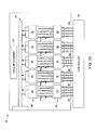
- FIG. 10 illustrates an embodiment of the multiple focal spot x-ray source 14 shown in FIGS. 1-9 .
- the x-ray source 14 includes a controller 64, a plurality of cathodes 66, a plurality of anodes 68, a high voltage and oil feedthrough 70, and a vacuum chamber 72.
- the plurality of anodes includes a first anode 74, a second anode 76, a third anode 78, a fourth anode 80, and a fifth anode 82.
- the plurality of cathodes includes a first cathode 84, a second cathode 86, a third cathode 88, a fourth cathode 90, and a fifth cathode 92.
- the controller is coupled to the first anode 74 via control lines 94, to the second anode 76 via control lines 96, to the third anode 78 via control lines 98, to the fourth anode 80 via control lines 100, and to the fifth anode 82 via control lines 102.
- the plurality of cathodes 66 emit electrons into the vacuum chamber 72, and the electrons are collected by the plurality of anodes 68, thus establishing electron beams 104, 106, 108, 110, and 112 through the x-ray tube 14.
- the electrons originate from the plurality of cathodes 66 and collide with the plurality of anodes 68, energy is generated and emitted as x-rays, for example, in a direction perpendicular to the electron beams 104, 106, 108, 110, and 112.
- the high voltage and oil feedthrough 70 accelerates the electrons as they flow through the x-ray tube.
- the controller 64 controls each of the anodes individually to control x-ray generation such that the previously described sets of projection images may be acquired.
- FIG. 11 illustrates a laminography inspection method 114 that may be utilized to operate the imaging system of FIG. 1 .
- the method 114 includes providing an object to the inspection area (block 116), for example, providing a pipe to an inspection area.
- the method 114 also includes irradiating the object at a desired angle with a stationary multiple focal spot x-ray source (block 118) and, after the x-rays are attenuated by the object, detecting at least a portion of the x-rays on the detector array (block 120).
- the acquired x-ray projection data is also stored (block 122), for example, to a memory of a control or processing system.
- the object is then irradiated at a variety of additional angles to obtain additional projection images while maintaining the x-ray source substantially stationary (block 124).
- the object is subsequently translated (block 126) and again irradiated at a plurality of angles to obtain another set of projection images at the second lengthwise location along the length of the object (block 128).
- the multiple focal spot x-ray source remains substantially stationary with respect to rotational and translational movement.
- the acquired x-ray data along the length of the object is then processed (block 130), and a determination is made as to whether the object is accepted, rejected, or flagged (block 132). That is, the object is inspected for the presence or absence of a defect, such as stress corrosion on a pipe.
- the object if the object fits within the boundary of the source detector active regions, there may be no movement of the object necessary to obtain laminographic data and to reconstruct planes of the object.
- the virtual motion of the source may substitute for the motion of the object.
- certain embodiments may be substantially stationary in that no moving parts are necessary, thus possibly reducing the complexity and monetary expense associated with making and operating the disclosed imaging systems.
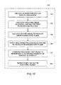
- FIG. 12 illustrates an embodiment of the processing step of FIG. 11 .
- the processing method 130 includes providing the acquired projection data to a processor (block 134). For example, a single set of projection data taken over a given angular range at one lengthwise location along the length of the object may be provided to the processor.
- the method 130 also includes shifting each acquired image within the set of projection data by a desired amount for the reconstruction of a first plane (block 136) and adding each shifted image to produce an unprocessed first plane (block 138). That is, as described above, the acquired projection images may be shifted and added to produce slices of the object at various volumetric depths. If desired, one or more deblurring or processing techniques may be utilized to remove out of focus artifacts to produce a processed first plane (block 140).
- the processed first plane may be compared to a reference to determine the presence or absence of a defect (block 142).
- the projection images within a given set may again be shifted by a second desired amount, added together, and processed to produce images of additional planes at different depths through the object (block 144).
- embodiments of the invention can include an increased inspection speed as compared to traditional systems. That is, the multiple focal spot x-ray systems disclosed herein are capable of electronically addressing each of the focal spots in a specific manner, thus allowing each focal spot to be activated and deactivated quickly (e.g., within 1 microsecond). Such features may reduce the length of time necessary to detect and characterize a defect in an industrial product. Further, the systems disclosed herein may offer additional technical advantages over single spot x-ray sources, such as the scalability of the generated power. The total power capable of being generated by embodiments of present invention may be substantially greater than many typical single spot x-ray sources. Additionally, in embodiments in which an object size fits within the active regions of the source detector configuration, movement of the x-ray source, the object, or the detector may not be necessary, thus possibly reducing or eliminating motion blur.
Landscapes
- Health & Medical Sciences (AREA)
- Immunology (AREA)
- Physics & Mathematics (AREA)
- Chemical & Material Sciences (AREA)
- Analytical Chemistry (AREA)
- Biochemistry (AREA)
- General Health & Medical Sciences (AREA)
- Life Sciences & Earth Sciences (AREA)
- Pathology (AREA)
- General Physics & Mathematics (AREA)
- Engineering & Computer Science (AREA)
- Nuclear Medicine, Radiotherapy & Molecular Imaging (AREA)
- Pulmonology (AREA)
- Radiology & Medical Imaging (AREA)
- Theoretical Computer Science (AREA)
- Analysing Materials By The Use Of Radiation (AREA)
Applications Claiming Priority (1)
| Application Number | Priority Date | Filing Date | Title |
|---|---|---|---|
| US12/969,350 US20110299653A1 (en) | 2010-12-15 | 2010-12-15 | Method and apparatus for laminography inspection |
Publications (2)
| Publication Number | Publication Date |
|---|---|
| EP2466295A2 true EP2466295A2 (de) | 2012-06-20 |
| EP2466295A3 EP2466295A3 (de) | 2013-02-27 |
Family
ID=45064468
Family Applications (1)
| Application Number | Title | Priority Date | Filing Date |
|---|---|---|---|
| EP11191601A Withdrawn EP2466295A3 (de) | 2010-12-15 | 2011-12-01 | Verfahren und Vorrichtung für die Laminografieprüfung |
Country Status (3)
| Country | Link |
|---|---|
| US (1) | US20110299653A1 (de) |
| EP (1) | EP2466295A3 (de) |
| CN (1) | CN102539456A (de) |
Families Citing this family (14)
| Publication number | Priority date | Publication date | Assignee | Title |
|---|---|---|---|---|
| JP5965799B2 (ja) * | 2012-09-20 | 2016-08-10 | 株式会社日立製作所 | X線断層撮影方法およびx線断層撮影装置 |
| CN103901488A (zh) * | 2012-12-27 | 2014-07-02 | 同方威视技术股份有限公司 | 固定式ct装置 |
| CN103901493B (zh) * | 2012-12-27 | 2016-12-28 | 同方威视技术股份有限公司 | 一种无机架ct装置 |
| GB201508064D0 (en) * | 2015-05-12 | 2015-06-24 | Rolls Royce Plc | A method of scanning aerofoil blades |
| GB201508065D0 (en) * | 2015-05-12 | 2015-06-24 | Rolls Royce Plc | A method of scanning Aerofoil blades |
| US11199531B2 (en) * | 2016-05-05 | 2021-12-14 | Epica International, Inc. | Diagnostic support for skins and inspection method of skin |
| HUP1600469A2 (en) * | 2016-07-27 | 2018-01-29 | Peter Teleki | Method for determining the geometric parameters and/or material state of a specimen based on in-situ radiographic imaging |
| US11145431B2 (en) * | 2016-08-16 | 2021-10-12 | Massachusetts Institute Of Technology | System and method for nanoscale X-ray imaging of biological specimen |
| WO2018035171A1 (en) * | 2016-08-16 | 2018-02-22 | Massachusetts Institute Of Technology | Nanoscale x-ray tomosynthesis for rapid analysis of integrated circuit (ic) dies |
| CN107764846B (zh) * | 2017-10-20 | 2020-04-14 | 重庆大学 | 一种正交直线扫描的cl成像系统及分析方法 |
| CN112534247B (zh) * | 2018-07-27 | 2025-02-11 | 深圳帧观德芯科技有限公司 | 多源锥束计算机断层扫描 |
| US11841332B2 (en) | 2019-01-25 | 2023-12-12 | Toray Industries, Inc. | Inspection method and manufacturing method for structure and inspection apparatus and manufacturing apparatus for structure |
| US11437218B2 (en) | 2019-11-14 | 2022-09-06 | Massachusetts Institute Of Technology | Apparatus and method for nanoscale X-ray imaging |
| DE112023001408T5 (de) * | 2022-03-15 | 2025-02-13 | Sigray, Inc. | System und verfahren für die kompakte laminographie unter verwendung einer mikrofokus-transmissionsröntgenquelle und eines röntgendetektors mit variabler vergrösserung |
Family Cites Families (14)
| Publication number | Priority date | Publication date | Assignee | Title |
|---|---|---|---|---|
| DE2658533C2 (de) * | 1976-12-23 | 1987-02-26 | Siemens AG, 1000 Berlin und 8000 München | Vorrichtung zur Darstellung von Körperlängsschichten |
| DE3037621A1 (de) * | 1980-10-04 | 1982-05-27 | Philips Patentverwaltung Gmbh, 2000 Hamburg | Durchleuchtungsanordnung zur aufnahme von schichtbildern eines dreidimensionalen objektes |
| US4903204A (en) * | 1987-12-01 | 1990-02-20 | Duke University | Matrix inversion tomosynthesis improvements in longitudinal X-ray slice imaging |
| US6292531B1 (en) * | 1998-12-31 | 2001-09-18 | General Electric Company | Methods and apparatus for generating depth information mammography images |
| US6373917B1 (en) * | 2000-08-30 | 2002-04-16 | Agilent Technologies, Inc. | Z-axis elimination in an X-ray laminography system using image magnification for Z plane adjustment |
| US6324249B1 (en) * | 2001-03-21 | 2001-11-27 | Agilent Technologies, Inc. | Electronic planar laminography system and method |
| JP3909048B2 (ja) * | 2003-09-05 | 2007-04-25 | ジーイー・メディカル・システムズ・グローバル・テクノロジー・カンパニー・エルエルシー | X線ct装置およびx線管 |
| JP2005245559A (ja) * | 2004-03-02 | 2005-09-15 | Ge Medical Systems Global Technology Co Llc | X線ct装置およびx線装置 |
| US8155262B2 (en) * | 2005-04-25 | 2012-04-10 | The University Of North Carolina At Chapel Hill | Methods, systems, and computer program products for multiplexing computed tomography |
| US20080019480A1 (en) * | 2006-07-24 | 2008-01-24 | Kuei-Wen Cheng | Method and apparatus for controlling x-ray machine to irradiate a narrowed portion |
| WO2009012453A1 (en) * | 2007-07-19 | 2009-01-22 | The University Of North Carolina At Chapel Hill | Stationary x-ray digital breast tomosynthesis systems and related methods |
| US7929659B2 (en) * | 2008-07-24 | 2011-04-19 | General Electric Company | System and method for generating computed tomography images |
| DE102008050352B4 (de) * | 2008-10-02 | 2012-02-16 | Siemens Aktiengesellschaft | Multi-Strahl-Röntgenvorrichtung |
| DE102009043421A1 (de) * | 2009-09-29 | 2011-04-07 | Siemens Aktiengesellschaft | Verfahren und Vorrichtung |
-
2010
- 2010-12-15 US US12/969,350 patent/US20110299653A1/en not_active Abandoned
-
2011
- 2011-12-01 EP EP11191601A patent/EP2466295A3/de not_active Withdrawn
- 2011-12-15 CN CN201110437105XA patent/CN102539456A/zh active Pending
Non-Patent Citations (1)
| Title |
|---|
| None |
Also Published As
| Publication number | Publication date |
|---|---|
| CN102539456A (zh) | 2012-07-04 |
| US20110299653A1 (en) | 2011-12-08 |
| EP2466295A3 (de) | 2013-02-27 |
Similar Documents
| Publication | Publication Date | Title |
|---|---|---|
| EP2466295A2 (de) | Verfahren und Vorrichtung für die Laminografieprüfung | |
| US11493458B2 (en) | Imaging system and method with scatter correction | |
| US9786041B2 (en) | CT systems and methods thereof | |
| US8094781B1 (en) | Portable X-ray back scattering imaging systems | |
| US8184767B2 (en) | Imaging system and method with scatter correction | |
| CN105806858A (zh) | Ct检测方法和ct设备 | |
| JP2008224448A (ja) | X線検査方法およびx線検査装置 | |
| US20110150174A1 (en) | Multiple x-ray tube system and method of making same | |
| JP4711759B2 (ja) | X線検査装置 | |
| US8901510B2 (en) | Particle beam device having a detector arrangement | |
| EP2703849A1 (de) | System zur Sicherheitsüberprüfung der Rückstreuung im menschlichen Körper und Abtastverfahren zum Erkennen von radioaktiver Materie | |
| CN115356359B (zh) | 激光加速驱动的高能微焦点x射线大视野ct成像装置 | |
| JP2010127810A (ja) | X線検査装置およびx線検査方法 | |
| TWI399780B (zh) | 包含場發射陰極之x射線源 | |
| US20260092882A1 (en) | X-ray imaging apparatus and x-ray tube | |
| JP5487519B2 (ja) | 産業用x線ct装置および撮像方法 | |
| JP7461102B2 (ja) | 医用画像処理装置およびx線ct装置 | |
| KR20070005036A (ko) | 2차원 참조검출기 및 참조 검출기용 콜리메이터를 포함하는고해상도 콘빔 엑스선 단층 촬영 장치 | |
| KR102790748B1 (ko) | Ct 영상품질 개선방법 및 이를 위한 시스템 | |
| Smolyanskiy et al. | X-ray tomography of the aerospace products | |
| US20250252623A1 (en) | Spatially varying artifact removal method for computed tomography | |
| KR102549748B1 (ko) | Ct 검사 장치 | |
| JP2003210453A (ja) | X線ct装置 | |
| Yenumula et al. | X-ray industrial computed laminography (ICL) simulation study of planar objects: Optimization of laminographic angle | |
| Bisbee et al. | Image Stitching in Neutron Radiography for Surface Extraction of Additively Manufactured Parts |
Legal Events
| Date | Code | Title | Description |
|---|---|---|---|
| PUAI | Public reference made under article 153(3) epc to a published international application that has entered the european phase |
Free format text: ORIGINAL CODE: 0009012 |
|
| AK | Designated contracting states |
Kind code of ref document: A2 Designated state(s): AL AT BE BG CH CY CZ DE DK EE ES FI FR GB GR HR HU IE IS IT LI LT LU LV MC MK MT NL NO PL PT RO RS SE SI SK SM TR |
|
| AX | Request for extension of the european patent |
Extension state: BA ME |
|
| PUAL | Search report despatched |
Free format text: ORIGINAL CODE: 0009013 |
|
| AK | Designated contracting states |
Kind code of ref document: A3 Designated state(s): AL AT BE BG CH CY CZ DE DK EE ES FI FR GB GR HR HU IE IS IT LI LT LU LV MC MK MT NL NO PL PT RO RS SE SI SK SM TR |
|
| AX | Request for extension of the european patent |
Extension state: BA ME |
|
| RIC1 | Information provided on ipc code assigned before grant |
Ipc: G01N 23/04 20060101ALI20130122BHEP Ipc: G01N 23/02 20060101AFI20130122BHEP |
|
| STAA | Information on the status of an ep patent application or granted ep patent |
Free format text: STATUS: THE APPLICATION IS DEEMED TO BE WITHDRAWN |
|
| 18D | Application deemed to be withdrawn |
Effective date: 20130828 |