EP2466410A1 - Verfahren und Vorrichtung zum automatischen Steuern eines Transportsystems - Google Patents
Verfahren und Vorrichtung zum automatischen Steuern eines Transportsystems Download PDFInfo
- Publication number
- EP2466410A1 EP2466410A1 EP20110193212 EP11193212A EP2466410A1 EP 2466410 A1 EP2466410 A1 EP 2466410A1 EP 20110193212 EP20110193212 EP 20110193212 EP 11193212 A EP11193212 A EP 11193212A EP 2466410 A1 EP2466410 A1 EP 2466410A1
- Authority
- EP
- European Patent Office
- Prior art keywords
- transport system
- distance
- slope
- traveled
- measuring device
- Prior art date
- Legal status (The legal status is an assumption and is not a legal conclusion. Google has not performed a legal analysis and makes no representation as to the accuracy of the status listed.)
- Granted
Links
- 238000000034 method Methods 0.000 title claims abstract description 13
- 238000005259 measurement Methods 0.000 claims description 18
- 238000010586 diagram Methods 0.000 description 4
- 230000001133 acceleration Effects 0.000 description 2
- 238000011156 evaluation Methods 0.000 description 2
- 238000012545 processing Methods 0.000 description 2
- 230000000630 rising effect Effects 0.000 description 2
- 238000012216 screening Methods 0.000 description 2
- 238000004140 cleaning Methods 0.000 description 1
- 238000004891 communication Methods 0.000 description 1
- 230000001419 dependent effect Effects 0.000 description 1
- 238000001514 detection method Methods 0.000 description 1
- 230000000694 effects Effects 0.000 description 1
- 231100001261 hazardous Toxicity 0.000 description 1
- 238000003032 molecular docking Methods 0.000 description 1
- 238000012544 monitoring process Methods 0.000 description 1
- NJPPVKZQTLUDBO-UHFFFAOYSA-N novaluron Chemical compound C1=C(Cl)C(OC(F)(F)C(OC(F)(F)F)F)=CC=C1NC(=O)NC(=O)C1=C(F)C=CC=C1F NJPPVKZQTLUDBO-UHFFFAOYSA-N 0.000 description 1
- 230000003287 optical effect Effects 0.000 description 1
- 230000001360 synchronised effect Effects 0.000 description 1
- 229910052724 xenon Inorganic materials 0.000 description 1
- FHNFHKCVQCLJFQ-UHFFFAOYSA-N xenon atom Chemical compound [Xe] FHNFHKCVQCLJFQ-UHFFFAOYSA-N 0.000 description 1
Images

Classifications
-
- G—PHYSICS
- G05—CONTROLLING; REGULATING
- G05D—SYSTEMS FOR CONTROLLING OR REGULATING NON-ELECTRIC VARIABLES
- G05D1/00—Control of position, course, altitude or attitude of land, water, air or space vehicles, e.g. using automatic pilots
- G05D1/02—Control of position or course in two dimensions
- G05D1/021—Control of position or course in two dimensions specially adapted to land vehicles
- G05D1/0231—Control of position or course in two dimensions specially adapted to land vehicles using optical position detecting means
- G05D1/0238—Control of position or course in two dimensions specially adapted to land vehicles using optical position detecting means using obstacle or wall sensors
Definitions
- the invention relates to a device for automated control of a transport system according to the preamble of independent claim 1 and a corresponding method.
- Control devices and corresponding methods for self-propelled transport systems are known from the prior art which detect and process surfaces of movable or immovable objects, in particular the driving ground or persons in the direction of travel of the transport system.
- EP 0290633 B1 discloses a method for detecting changes in the cab of an unmanned vehicle.
- a contactless sensor by means of a contactless sensor and processing of the measured values for the control of the vehicle from at least one of at least two spaced openings on the vehicle, a raster projection in the direction of travel is radiated onto the road and from at least one other opening of the raster projection and the front of the vehicle Space image sequences recorded, wherein the raster changes cause after processing in real time control of the unmanned vehicle.
- the document DE 10196988 T5 discloses a mobile robotic system for performing a variety of separate activities, such as docking of operating modules, comprising at least one autonomous mobile robot with wheels having at least one wheel drive motor; a built-in computer; Navigation, alignment and maneuvering means in a mobile obstacle environment; a sensor system and a wireless communication system for receiving and transmitting signals.
- the robotic system includes means for monitoring along the sides of the autonomous mobile robot using a pair of cameras or a pair of infrared sensors, thereby intending to enable the robot to avoid collisions with walls and any objects, that could come close to one of the sides of the robot.
- EP-358628 a navigation system for a driverless transport vehicle is known, which also detects level differences in the surface to be traveled in addition to the larger obstacles located in front of the vehicle and generates a control signal for bypassing them.
- US 4986384 also describes a control system for a driverless transport vehicle, which detects irregularities of the surface to be traveled by means of a surface detector and generates a corresponding control signal.
- the transport system according to the invention is capable of automatically recognizing an abyss or non-drivable surface and distinguishing it from a drivable obstacle, as well as halting insurmountable obstacles based on the control signal or making corresponding steering maneuvers ,
- the self-driving vehicle is stopped or slowed down and driven an evasive maneuver to prevent about a crash.
- the transport system comprises variable in its acceleration and steerable and / or controllable wheels, which are automatically controlled by the control device and the measuring device comprises a plurality of measuring modules for detecting distance measured values of each corresponding local measuring range, wherein the measuring modules with respect to the wheels of the transport system are horizontally spaced so that a corresponding control signal can be generated based on the distance measurement values of depressions and / or elevations of the surface adjacent to the wheels.
- the transport system according to the invention is therefore suitable for safe automated transport against hazardous or special items such as hospitals, laboratories, warehouses and the like, as well as for the operation of service equipment, such as cleaning systems, etc., the transport system safely circumvents any abysses or steep ramps or stops in time ,
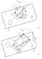
- FIG. 1 and FIG. 2 illustrate in each case a schematically illustrated inventive transport system with two drive and two trackable steering wheels, wherein the transport system is stopped in good time on a surface to be traveled before reaching an abyss.
- the steering wheels can also be designed as follower rollers.
- the transport system designated here by reference numeral 1, comprises an automated control device and a measuring device 11 for acquiring distance measurement values with regard to the distance between the measuring device 11 and a surface 9 to be traveled and transmitting a control signal which can be generated on the basis of the acquired distance measured values to the control device the measuring device 11 is designed to selectively compare distance measurement values acquired in a local measuring range of the measuring device 11 with a distance limit value and to generate a corresponding control signal for controlling the transport device 1 when it is exceeded.
- the transport system 1 includes variable in its acceleration and steerable and / or controllable wheels 101, which are automatically controlled by the control device.
- the measuring device 11 comprises a plurality of measuring modules 110 for acquiring distance measuring values of a respectively corresponding local measuring area, wherein the measuring modules 110 are horizontally spaced with respect to the wheels 101 of the transport system 1 in such a way that based on the distance measuring values of depressions and / or elevations of the surface adjacent to the wheels corresponding control signal can be generated.
- the distance measurements are by the inventive measuring device 11 reliably detected even when partially wet or dark surface.
- the measurement modules 110 are preferably arranged to have a minimum distance from the wheels 101 so that there is sufficient response time at a particular speed of the transport system to generate and transmit a control signal based on the acquired distance measurements.
- the measuring modules are, for example, arranged on the underside of the transport system or are capable of performing a distance measurement from an opening of the underside.
- the measurement modules 110 can also be arranged on a pedestal of the transport system at a specific angle so that the local measurement area comes to lie in front of the wheels.
- the measuring device 11 preferably also has at least one distance measuring module 111 for detecting distance measured values of a horizontal distance measuring range 1110 spaced from the surface 9, based on which distance measured values a corresponding control signal can be generated. So safety stops of the transport system can be carried out even if no abyss has been detected.
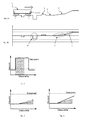
- FIG. 3a Illustrates a schematic representation of a transport system 1 according to the invention on a surface 9 to be traveled, the latter having different recesses, elevations and ramps;
- FIG. 3b Illustrates in a schematic diagram the means of the measuring device 11 of the inventive transport system 1 in Fig. 3a recorded distance measured values of the entire surface 9 to be traveled on a horizontal axis;
- FIGS. 4, 5 and 6 each show a designated in dashed circle detail view FIG. 3b , where a distinction can be made between permissible and non-permissible measured value ranges, based on which corresponding control signals can be generated by means of the measuring device 11 in order to control the transport system 1 in accordance with the nature of the surface 9.
- FIG. 4 illustrates a plurality of distance measurement values acquired temporally successively, which lie outside a constant distance limit value. Since the measuring modules are spaced horizontally to the wheels, such a chasm can be detected and timely generated a corresponding control signal and the transport system 1 are stopped to prevent a crash.
- the local measuring range of the surface 9 to be measured is selected by a distance or distance between a steering or driving wheel of the transport system 1 and the measuring point of the measuring range furthest from the corresponding wheel such that the time required to generate the control signal and control the transport system 1 Time is less than the quotient of the said distance and the travel speed of the transport system 1.
- Optical distance sensors such as laser distance sensors, have a substantially punctual, so small-scale measuring range.
- FIG. 5 shows a portion of the surface to be traveled 9, wherein by means of the detected distance measured values a ramp to be traveled is detected. This is achieved by means of a weighting module of the measuring device 11, wherein a permissible distance limit range or reference value is read from a lookup table and wherein a newly acquired distance measurement value is used only to generate the control signal, if it is outside the distance limit range, to drive on the ramps to enable.
- FIG. 6 shows a portion of the surface to be traveled 9, in which the apparent ramp is too steep to be driven by the transport system 1.
- an allowable gradient range with a hatched area is illustrated, whereby the distance measurement values actually recorded are outside this permissible range. If the transport system 1 according to the invention wanted to drive on this gradient, distance limit values would be exceeded and a corresponding control signal, for example a stop signal, would be generated and the transport system would be stopped.
- FIG. 7 11 illustrates a schematic block diagram of the transport system 1 according to the invention, wherein corresponding distance measurement values with respect to the surface 9 are respectively detected by means of a plurality of measuring modules 110 of the measuring device 11 of the transport system.
- the drive for example an electric motor M of a wheel
- the measuring device 11 comprises a guideway measuring module 112 for detecting a traveled distance s, wherein the measuring device is additionally configured to generate a corresponding control signal based on the quotient of the difference between successive distance measured values and the detected driving distance such that the permissible rising and / or falling ramps can be detected are.
- the distance measured values in combination with the traveled route.
- a corresponding control signal for example a stop signal, is generated by means of the control device.
- Reference numeral 113 denotes a weighting module of the type described above.
- the Fahrwegmessmodul is in the present embodiment, a rotary encoder, preferably an encoder, which detects the angular movement of the drive wheel, from which with respect to the wheel diameter of the distance traveled is determined.
- the slope is calculated continuously from this distance measured value and the distance measured value.
- a slope or a gradient is defined as passable or insurmountable.
- Abrupt changes of the traveled surface such as an abyss, are recognized by this system as surfaces whose steepness is too large to be drivable, and therefore lead to an evasive maneuver or to stop the transport vehicle.
Landscapes
- Physics & Mathematics (AREA)
- Engineering & Computer Science (AREA)
- Electromagnetism (AREA)
- Aviation & Aerospace Engineering (AREA)
- Radar, Positioning & Navigation (AREA)
- Remote Sensing (AREA)
- General Physics & Mathematics (AREA)
- Automation & Control Theory (AREA)
- Control Of Position, Course, Altitude, Or Attitude Of Moving Bodies (AREA)
Abstract
Description
- Die Erfindung betrifft eine Vorrichtung zum automatisierten Steuern eines Transportsystems gemäss dem Oberbegriff des unabhängigen Patentanspruchs 1 sowie ein entsprechendes Verfahren.
- Aus dem Stand der Technik sind Steuervorrichtungen und entsprechende Verfahren für selbstfahrende Transportsysteme bekannt, welche Oberflächen von beweglichen oder unbeweglichen Objekten, insbesondere des Fahrgrundes oder Personen in Fahrtrichtung des Transportsystems, erfassen und verarbeiten.
- So wird in der Patentschrift
EP 0290633 B1 ein Verfahren zum Erkennen von Änderungen im Fahrraum eines unbemannten Fahrzeugs offenbart. Hierbei wird mittels eines berührungslosen Aufnehmers sowie einer Verarbeitung der Messwerte für die Steuerung des Fahrzeugs aus mindestens einer von mindestens zwei beabstandeten Öffnungen am Fahrzeug eine Rasterprojektion in Fahrtrichtung auf die Fahrbahn abgestrahlt und von mindestens einer anderen Öffnung von der Rasterprojektion und von dem vor dem Fahrzeug befindlichen Raum Bildfolgen aufgenommen, wobei die Rasteränderungen nach Verarbeitung in Echtzeit eine Steuerung des unbemannten Fahrzeugs veranlassen. - Einer der Nachteile dieses Verfahrens sowie der entsprechenden Vorrichtung besteht darin, dass ein optisch wahrnehmbares räumliches Raster in den Raum vor dem Fahrzeug ausgesendet und mittels einer Videokamera erfasst werden muss. Die Auswertung der erfassten Bilddaten in Echtzeit hat sich als sehr rechenintensiv und daher nachteilig erwiesen. Daher ist die zu wählende Auflösung der Rasterung der erfassbaren Objekte derart zu wählen, dass die Auswertung schnell genug erfolgen kann. Ein anderer Nachteil besteht darin, dass die Rasterung wie vorgeschlagen durch einen mit der Videokamera synchronisierten Xenon Blitz erfolgt, so dass bestimmte Einsatzgebiete des Verfahrens, wie etwa in Reinräumen, ausgenommen sind.
- Das Dokument
DE 10196988 T5 offenbart ein mobiles Robotersystem zur Ausführung einer Vielzahl von separaten Tätigkeiten, wie etwa dem Andocken von Betriebsmodulen, das wenigstens einen autonomen mobilen Roboter mit Rädern mit wenigstens einem Radantriebsmotor aufweist; einen eingebauten Computer; Mittel zur Navigation, Ausrichtung und Manövrierung in einer Umgebung mit beweglichen Hindernissen; ein Sensorsystem und ein drahtloses Kommunikationssystem zum Empfangen und Senden von Signalen enthält. Insbesondere umfasst das Robotersystem Mittel zur Überwachung entlang der Seiten des autonomen mobilen Roboters unter Verwendung eines Paars von Kameras oder eines Paars von Infrarotsensoren, wobei damit beabsichtig ist, dem Roboter zu ermöglichen bzw. sie zu aktivieren, Kollisionen mit Wänden und irgendwelchen Gegenständen zu vermeiden, die einer der Seiten des Roboters nahe kommen könnten. - Einer der Nachteile dieser Vorrichtung besteht darin, dass die beiden seitlich angeordneten Infrarotabstandsmesssensoren oder Kameras einen eingeschränkten Sektor erfassen und somit in Fahrtrichtung vorhandene Hindernisse übersehen werden. Zudem ist die Anordnung sperrig und schränkt die Bewegungsfreiheit des Systems ein.
- Aus
EP-358628 US-4986384 beschreibt ebenfalls ein Steuerungssystem für ein fahrerloses Transportfahrzeug, welches mittels eines Oberflächendetektors Unregelmässigkeiten der zu befahrenden Oberfläche erfasst und ein entsprechendes Steuersignal generiert. - Alle bekannten Systeme zur Steuerung von fahrerlosen Fahrzeugen dienen dazu, unüberwindliche Hindernissen aller Art, also auch Unregelmässigkeiten der zu befahrenden Oberfläche, die durch Vergleich mit einem Grenzwert als unüberwindlich definiert werden, auszuweichen. Derartige Navigationssysteme, die ein Ausweichsignal von einem direkten Vergleich eines gemessenen Abstandswerts mit einem festgelegten Grenzwert gewinnen, sind nicht in der Lage zwischen unüberwindlichen Hindernissen und befahrbaren Hindernissen, z.B. Rampen, zu unterscheiden.
- Es ist daher Aufgabe der vorliegenden Erfindung, eine Vorrichtung und ein Verfahren zum automatisierten Steuern eines selbstfahrenden Transportsystems bereitzustellen, welches die Nachteile des Stands der Technik nicht aufweist, insbesondere eine Unterscheidung von unüberwindlichen und befahrbaren Hindernissen ermöglicht.
- Erfindungsgemäss wird diese Aufgabe gelöst durch eine Vorrichtung sowie ein Verfahren zum automatisierten Steuern eines Transportsystems mit den im kennzeichnenden Teil der unabhängigen Ansprüche angegebenen Merkmalen.
- Einer der Vorteile der Erfindung besteht darin, dass das erfindungsgemässe Transportsystem in der Lage ist, automatisiert einen Abgrund oder eine nicht befahrbare Oberfläche zu erkennen und von einem befahrbaren Hindernis zu unterscheiden, sowie nur bei unüberwindlichen Hindernissen basierend auf dem Steuersignal anzuhalten oder entsprechende Lenkmanöver zu tätigen. Insbesondere ist vorteilhaft, dass nicht nur bewegliche und unerwartete Objekte in einer Fahrtrichtung erfassbar sind, sondern auch, dass nicht bekannte Vertiefungen oder Erhebungen des Fahruntergrunds rechtzeitig erkannt werden. Diesfalls wird das selbstfahrende Fahrzeug gestoppt oder verlangsamt und ein Ausweichmanöver gefahren, um etwa einen Absturz zu verhindern.
- Vorteilhafte Ausgestaltungen des erfindungsgemässen Transportsystems sind den abhängigen Ansprüchen zu entnehmen.
- Das Transportsystem umfasst in ihrer Beschleunigung veränderbare sowie lenkbare und/oder steuerbare Räder, welche mittels der Steuervorrichtung automatisiert steuerbar sind und die Messvorrichtung umfasst mehrere Messmodule zum Erfassen von Abstandsmesswerten eines jeweils entsprechenden lokalen Messbereichs, wobei die Messmodule bezüglich den Rädern des Transportsystems derart horizontal beabstandet sind, dass anhand der Abstandsmesswerte von zu den Rädern benachbarten Vertiefungen und/oder Erhöhungen der Oberfläche ein entsprechendes Steuersignal generierbar ist.
- Das erfindungsgemässe Transportsystem eignet sich daher für den sicheren automatisierten Transport vor Gefahr- oder Sondergut etwa in Spitälern, Laboratorien, Lagerhäusern und dergleichen, sowie zum Betrieb von Dienstleistungsgeräten, wie Reinigungssystemen etc., wobei das Transportsystem eventuelle Abgründe oder steile Rampen sicher umgeht oder rechtzeitig stoppt.
- Die Erfindung soll nachstehend anhand der schematischen Zeichnung näher erläutert werden. Es zeigen:
-
Fig. 1 ein schematisch dargestelltes erfindungsgemässes Transportsystem mit zwei Antriebs- und zwei nachführbaren Lenkrädern, wobei das Transportsystem auf einer zu befahrenden Oberfläche vor Erreichen eines Abgrunds rechtzeitig angehalten wird; -
Fig. 2 ein schematisch dargestelltes erfindungsgemässes Transportsystem mit einer anderen Ausführung, wobei das Transportsystem ebenfalls vor einem Abgrund rechtzeitig angehalten wird; -
Fig. 3a zeigt in einer schematischen Darstellung ein erfindungsgemässes Transportsystem auf einer zu befahrenden Oberfläche, wobei diese verschiedene Vertiefungen, Erhebungen und Rampen aufweist; -
Fig. 3b zeigt in einem schematischen Diagramm die mittels der Messvorrichtung des erfindungsgemässen Transportsystems inFig. 3a erfassten Abstandsmesswerte der gesamten zu befahrenden Oberfläche auf einer Horizontalachse; -
Fig. 4, 5 und 6 zeigen jeweils eine in gestrichelter Kreislinie bezeichnete Detailansicht ausFig. 3b , wobei zwischen zulässigen und nicht zulässigen Messwertebereichen unterschieden werden kann, basierend auf welchen entsprechende Steuersignale mittels der Messvorrichtung erzeugbar sind, um das Transportsystem entsprechend der Beschaffenheit der Oberfläche zu steuern, und -
Fig. 7 zeigt ein schematisches Blockschaltbild des erfindungsgemässen Transportsystems. -
Figur 1 und Figur 2 illustrieren jeweils ein schematisch dargestelltes erfindungsgemässes Transportsystem mit zwei Antriebs- und zwei nachführbaren Lenkrädern, wobei das Transportsystem auf einer zu befahrenden Oberfläche vor Erreichen eines Abgrunds rechtzeitig angehalten wird. Die Lenkräder können auch als Nachlaufrollen ausgebildet sein. Das Transportsystem, hier mit Bezugszeichen 1 bezeichnet, umfasst eine automatisierte Steuervorrichtung sowie eine Messvorrichtung 11 zum Erfassen von Abstandsmesswerten hinsichtlich des Abstands zwischen der Messvorrichtung 11 und einer zu befahrenden Oberfläche 9 und zum Übertragen eines basierend auf den erfassten Abstandsmesswerten generierbaren Steuersignals an die Steuervorrichtung, wobei die Messvorrichtung 11 ausgebildet ist, in einem lokalen Messbereich der Messvorrichtung 11 erfasste Abstandsmesswerte selektiv mit einem Abstandsgrenzwert zu vergleichen und um bei Überschreiten desselben ein entsprechendes Steuersignal zur Steuerung der Transportvorrichtung 1 zu generieren. - Das Transportsystem 1 umfasst in ihrer Beschleunigung veränderbare sowie lenkbare und/oder steuerbare Räder 101, welche mittels der Steuervorrichtung automatisiert steuerbar sind.
- Die Messvorrichtung 11 umfasst mehrere Messmodule 110 zum Erfassen von Abstandsmesswerten eines jeweils entsprechenden lokalen Messbereichs, wobei die Messmodule 110 bezüglich der Räder 101 des Transportsystems 1 derart horizontal beabstandet sind, dass anhand der Abstandsmesswerte von zu den Rädern benachbarten Vertiefungen und/oder Erhöhungen der Oberfläche ein entsprechendes Steuersignal generierbar ist. Die Abstandsmesswerte werden durch die erfindungsgemässe Messvorrichtung 11 auch bei teilweise nasser oder bei dunkler Oberfläche zuverlässig erfasst.
- Die Messmodule 110 sind vorzugsweise so angeordnet, dass sie zu den Rädern 101 einen Minimalabstand aufweisen, so dass genügend Reaktionszeit bei einer bestimmten Geschwindigkeit des Transportsystems vorhanden ist, um ein Steuersignal basierend auf den erfassten Abstandsmesswerten zu generieren und der Steuervorrichtung zu übertragen. Die Messmodule sind bspw. auf der Unterseite des Transportsystems angeordnet bzw. sind in der Lage, aus einer Öffnung der Unterseite heraus eine Abstandsmessung durchzuführen. Die Messmodule 110 können auch auf einem Sockel des Transportsystems in einem bestimmten Winkel angeordnet sein, so dass der lokale Messbereich vor den Rädern zu liegen kommt.
- Die Messvorrichtung 11 weist vorzugsweise auch mindestens ein Distanzmessmodul 111 zum Erfassen von Distanzmesswerten eines zur Oberfläche 9 beabstandeten horizontalen Distanzmessbereichs 1110 auf, basierend auf welchen Distanzmesswerten ein entsprechendes Steuersignal generierbar ist. So können auch Sicherheitsstopps des Transportsystems durchgeführt werden, selbst, wenn kein Abgrund erfasst worden ist.
-
Figur 3a illustriert in einer schematischen Darstellung ein erfindungsgemässes Transportsystem 1 auf einer zu befahrenden Oberfläche 9, wobei diese verschiedene Vertiefungen, Erhebungen und Rampen aufweist; -
Figur 3b illustriert in einem schematischen Diagramm die mittels der Messvorrichtung 11 des erfindungsgemässen Transportsystems 1 inFig. 3a erfassten Abstandsmesswerte der gesamten zu befahrenden Oberfläche 9 auf einer Horizontalachse; -
Figuren 4, 5 und 6 zeigen jeweils eine in gestrichelter Kreislinie bezeichnete Detailansicht ausFigur 3b , wobei zwischen zulässigen und nicht zulässigen Messwertebereichen unterschieden werden kann, basierend auf welchen entsprechende Steuersignale mittels der Messvorrichtung 11 erzeugbar sind, um das Transportsystem 1 entsprechend der Beschaffenheit der Oberfläche 9 zu steuern. -
Figur 4 illustriert eine Vielzahl zeitlich nacheinander erfasster Abstandsmesswerte, welche ausserhalb eines konstanten Abstandsgrenzwerts liegen. Da die Messmodule horizontal zu den Rädern beabstandet sind, kann ein solcher Abgrund erkannt und rechtzeitig ein entsprechendes Steuersignal generiert und das Transportsystem 1 angehalten werden, um einen Absturz zu verhindern. Dabei ist der lokale Messbereich der zu messenden Oberfläche 9 durch eine Strecke oder Abstand zwischen einem Lenk- oder Antriebsrad des Transportsystems 1 und dem zum entsprechenden Rad am weitesten beabstandete Messpunkt des Messbereichs derart gewählt, dass die zum Generieren des Steuersignals und Steuern des Transportsystems 1 erforderliche Zeit geringer ist als der Quotient der besagten Strecke und der Fahrgeschwindigkeit des Transportsystems 1. Optische Abstandssensoren, wie etwa Laserabstandssensoren, weisen einen im Wesentlichen punktuellen, also kleinflächigen Messbereich auf. -
Figur 5 zeigt einen Abschnitt der zu befahrenden Oberfläche 9, wobei mittels der erfassten Abstandsmesswerte eine zu befahrende Rampe erkannt wird. Dies wird mittels eines Gewichtungsmoduls der Messvorrichtung 11 erreicht, wobei ein zulässiger Abstandsgrenzwertbereich bzw. Referenzwert aus einer Lookup-Table ausgelesen wird und wobei ein neu erfasster Abstandsmesswert nur zum Generieren des Steuersignals herangezogen wird, falls er ausserhalb des Abstandsgrenzwertbereichs liegt, um ein Befahren der Rampen zu ermöglichen. -
Figur 6 zeigt einen Abschnitt der zu befahrenden Oberfläche 9, bei welcher die ersichtliche Rampe zu steil ist, um vom Transportsystem 1 befahren zu werden. Es wird hier also ein zulässiger Steigungsbereich mit schraffierter Fläche illustriert, wobei die effektiv erfassten Abstandsmesswerte ausserhalb dieses zulässigen Bereichs liegen. Würde das erfindungsgemässe Transportsystem 1 diese Steigung befahren wollen, so würden Abstandsgrenzwerte überschritten und ein entsprechendes Steuersignal, bspw. Stoppsignal, generiert und das Transportsystem angehalten. -
Figur 7 illustriert ein schematisches Blockschaltbild des erfindungsgemässen Transportsystems 1, wobei mittels mehreren Messmodulen 110 der Messvorrichtung 11 des Transportsystems jeweils entsprechende Abstandsmesswerte bezüglich der Oberfläche 9 erfasst werden. Basierend auf den erfassten Abstandsmesswerten wird der Antrieb, bspw. ein Elektromotor M eines Rads, gesteuert. Die Messvorrichtung 11 umfasst ein Fahrwegmessmodul 112 zum Erfassen einer zurückgelegten Fahrstrecke s, wobei die Messvorrichtung zudem eingerichtet ist, basierend auf dem Quotienten der Differenz aufeinanderfolgender Abstandsmesswerte und der erfassten Fahrstrecke ein entsprechendes Steuersignal zu generieren, derart, dass zulässige ansteigende und/oder abfallende Rampen detektierbar sind. Es erfolgt also eine dynamische Erfassung der Abstandsmesswerte in Kombination mit der zurückgelegten Fahrstrecke. Anders ausgedrückt ist es möglich, den dynamischen Verlauf des Abstands zwischen Abstandssensor und befahrener Oberfläche und damit die Neigung der befahrenen Fläche zu bestimmen. Falls die detektierte ansteigende und/oder abfallende Rampe nach Vergleich mit einem Referenzwert unzulässig ist, wird mittels der Steuervorrichtung ein entsprechendes Steuersignal, bspw. Stoppsignal erzeugt. Mit Bezugszeichen 113 ist ein Gewichtungsmodul der oben beschriebenen Art bezeichnet. - Das Fahrwegmessmodul ist beim vorliegenden Ausführungsbeispiel ein Drehgeber, vorzugsweise ein Encoder, welcher die Winkelbewegung des Antriebsrads erfasst, aus welcher mit Bezug zum Raddurchmesser der zurückgelegte Weg bestimmt wird. Aus diesem Wegmesswert und dem Abstandsmesswert wird kontinuierlich die Steigung berechnet. Durch Vergleich mit einem Grenzwert für die Steigung wird eine Steigung bzw. ein Gefälle als befahrbar oder unüberwindlich definiert.
- Sprunghafte Änderungen der befahrenen Oberfläche, wie z.B. ein Abgrund, werden von diesem System als Flächen erkannt, deren Steilheit zu gross ist um befahrbar zu sein, und führen deshalb zu einem Ausweichmanöverr oder zum Anhalten des Transport fahrzeugs.
-
- 1
- Transportsystem
- 10
- Steuervorrichtung
- 101
- Rad
- 11
- Messvorrichtung
- 110
- Messmodul
- 111
- Distanzmessmodul
- 1110
- horizontaler Distanzmessbereich
- 112
- Fahrwegmessmodul
- 113
- Gewichtungsmodul
- 9
- Oberfläche
- s
- Fahrstrecke
Claims (5)
- Verfahren zum automatisierten Steuern eines fahrerlosen Transportsystems, bei welchem kontinuierlich der Abstand zwischen einer am Transportsystem befindlichen Messvorrichtung und einer zu befahrenden Oberfläche erfasst wird und die erfassten Abstandsmesswerte zur Generierung eines Steuersignals zum Steuern des Transportsystems verwendet werden, dadurch gekennzeichnet, dass zusätzlich zu den Abstandsmesswerten kontinuierlich die Fahrstrecke des Transportsystems erfasst und aus dem Abstandsmesswert und der Fahrstrecke die Steigung der zu befahrenden Oberfläche berechnet wird und ein aus der berechneten Steigung abgeleitetes Signal an eine Steuereinrichtung zur Steuerung des Transportsystems übertragen wird.
- Verfahren nach Anspruch 1, dadurch gekennzeichnet, dass die berechnete Steigung mit einem festgelegten Grenzwert verglichen wird, unterhalb dessen eine Steigung befahrbar ist.
- Verfahren nach Anspruch 2, dadurch gekennzeichnet, dass bei einer berechneten Steigung über dem Grenzwert ein Umlenkungs- oder Stoppsignal an die Steuereinrichtung übertragen wird.
- Automatisch gesteuertes, fahrerloses Transportsystem mit einer Messvorrichtung (11) zum Erfassen des Abstands zwischen der Messvorrichtung und einer zu befahrenden Oberfläche und zur Generierung eines Steuersignals zum Steuern des Transportsystems, gekennzeichnet durch eine Fahrwegsmesseinrichtung (112) zum Erfassen einer zurückgelegten Fahrstrecke, eine Recheneinheit zur Berechnung der Steigung der Oberfläche aus den Abstandsmesswerten und der Fahrstrecke und eine Steuereinheit zur Steuerung der Transportsystems mittels eines von der Recheneinheit generierten Steuersignals.
- Transportsystem nach Anspruch 4, dadurch gekennzeichnet, dass die Recheneinheit eine Vergleichseinheit zum Vergleich der berechneten Steigung mit einem festgelegten Grenzwert umfasst, unterhalb dessen eine Steigung für das Transportsystem befahrbar ist.
Priority Applications (1)
| Application Number | Priority Date | Filing Date | Title |
|---|---|---|---|
| EP20110193212 EP2466410B1 (de) | 2010-12-15 | 2011-12-13 | Verfahren und Vorrichtung zum automatischen Steuern eines Transportsystems |
Applications Claiming Priority (2)
| Application Number | Priority Date | Filing Date | Title |
|---|---|---|---|
| EP20100195237 EP2466409B1 (de) | 2010-12-15 | 2010-12-15 | Verfahren und Vorrichtung zum automatisierten Steuern eines Transportsystems |
| EP20110193212 EP2466410B1 (de) | 2010-12-15 | 2011-12-13 | Verfahren und Vorrichtung zum automatischen Steuern eines Transportsystems |
Publications (2)
| Publication Number | Publication Date |
|---|---|
| EP2466410A1 true EP2466410A1 (de) | 2012-06-20 |
| EP2466410B1 EP2466410B1 (de) | 2014-05-21 |
Family
ID=44343956
Family Applications (2)
| Application Number | Title | Priority Date | Filing Date |
|---|---|---|---|
| EP20100195237 Not-in-force EP2466409B1 (de) | 2010-12-15 | 2010-12-15 | Verfahren und Vorrichtung zum automatisierten Steuern eines Transportsystems |
| EP20110193212 Not-in-force EP2466410B1 (de) | 2010-12-15 | 2011-12-13 | Verfahren und Vorrichtung zum automatischen Steuern eines Transportsystems |
Family Applications Before (1)
| Application Number | Title | Priority Date | Filing Date |
|---|---|---|---|
| EP20100195237 Not-in-force EP2466409B1 (de) | 2010-12-15 | 2010-12-15 | Verfahren und Vorrichtung zum automatisierten Steuern eines Transportsystems |
Country Status (2)
| Country | Link |
|---|---|
| EP (2) | EP2466409B1 (de) |
| DK (2) | DK2466409T3 (de) |
Cited By (1)
| Publication number | Priority date | Publication date | Assignee | Title |
|---|---|---|---|---|
| CN110235074A (zh) * | 2017-04-26 | 2019-09-13 | 深圳市元征科技股份有限公司 | 医疗车的自动行驶方法及装置 |
Citations (6)
| Publication number | Priority date | Publication date | Assignee | Title |
|---|---|---|---|---|
| EP0290633B1 (de) | 1987-05-09 | 1989-11-02 | Carl Schenck Ag | Verfahren zum Erkennen von Änderungen in Fahrraum eines unbemannten Fahrzeuges |
| EP0358628A2 (de) | 1988-09-06 | 1990-03-14 | Transitions Research Corporation | Strukturiertes Lichtsystem für optische Navigation und zum Ausweichen vor Hindernissen |
| US4986384A (en) | 1988-10-19 | 1991-01-22 | Robotech Laboratory Co., Ltd. | Remote control system of mobile objects |
| DE10196988T5 (de) | 2000-12-04 | 2004-04-15 | Abb Ab | Robotersystem |
| US20070156286A1 (en) * | 2005-12-30 | 2007-07-05 | Irobot Corporation | Autonomous Mobile Robot |
| WO2008060689A2 (en) * | 2006-10-06 | 2008-05-22 | Irobot Corporation | Autonomous behaviors for a remote vehicle |
Family Cites Families (1)
| Publication number | Priority date | Publication date | Assignee | Title |
|---|---|---|---|---|
| US7069124B1 (en) * | 2002-10-28 | 2006-06-27 | Workhorse Technologies, Llc | Robotic modeling of voids |
-
2010
- 2010-12-15 DK DK10195237T patent/DK2466409T3/da active
- 2010-12-15 EP EP20100195237 patent/EP2466409B1/de not_active Not-in-force
-
2011
- 2011-12-13 EP EP20110193212 patent/EP2466410B1/de not_active Not-in-force
- 2011-12-13 DK DK11193212T patent/DK2466410T3/da active
Patent Citations (6)
| Publication number | Priority date | Publication date | Assignee | Title |
|---|---|---|---|---|
| EP0290633B1 (de) | 1987-05-09 | 1989-11-02 | Carl Schenck Ag | Verfahren zum Erkennen von Änderungen in Fahrraum eines unbemannten Fahrzeuges |
| EP0358628A2 (de) | 1988-09-06 | 1990-03-14 | Transitions Research Corporation | Strukturiertes Lichtsystem für optische Navigation und zum Ausweichen vor Hindernissen |
| US4986384A (en) | 1988-10-19 | 1991-01-22 | Robotech Laboratory Co., Ltd. | Remote control system of mobile objects |
| DE10196988T5 (de) | 2000-12-04 | 2004-04-15 | Abb Ab | Robotersystem |
| US20070156286A1 (en) * | 2005-12-30 | 2007-07-05 | Irobot Corporation | Autonomous Mobile Robot |
| WO2008060689A2 (en) * | 2006-10-06 | 2008-05-22 | Irobot Corporation | Autonomous behaviors for a remote vehicle |
Cited By (1)
| Publication number | Priority date | Publication date | Assignee | Title |
|---|---|---|---|---|
| CN110235074A (zh) * | 2017-04-26 | 2019-09-13 | 深圳市元征科技股份有限公司 | 医疗车的自动行驶方法及装置 |
Also Published As
| Publication number | Publication date |
|---|---|
| DK2466409T3 (da) | 2014-06-23 |
| DK2466410T3 (da) | 2014-09-01 |
| EP2466410B1 (de) | 2014-05-21 |
| EP2466409A1 (de) | 2012-06-20 |
| EP2466409B1 (de) | 2014-03-19 |
Similar Documents
| Publication | Publication Date | Title |
|---|---|---|
| EP3260357B1 (de) | Fahrzeug mit rangiersystem | |
| DE102015201317B4 (de) | Vermessen einer Abmessung auf einer Oberfläche | |
| EP2764812B1 (de) | Reinigungsroboter | |
| EP2867874B1 (de) | Interaktion zwischen einem mobilen roboter und einer alarmanlage | |
| EP3356203B1 (de) | Verfahren zum bestimmen einer parkfläche zum parken eines kraftfahrzeugs, fahrerassistenzsystem sowie kraftfahrzeug | |
| WO2012110343A1 (de) | Verfahren zur autarken lokalisierung eines fahrerlosen, motorisierten fahrzeugs | |
| DE102009034848B4 (de) | Optoelektronischer Sensor | |
| DE102014216763A1 (de) | Selbstfahrende Fräsmaschine, sowie Verfahren zum Abladen von Fräsgut | |
| WO2016180414A1 (de) | Vorrichtung zur bestimmung eines für ein fahrzeug befahrbaren raums, entsprechendes verfahren und fahrzeug | |
| DE102018116065A1 (de) | Verfahren zum Betrieb eines sich selbsttätig fortbewegenden Servicegerätes | |
| WO2015197206A1 (de) | Vorrichtung und verfahren zur bestimmung mindestens einer eigenschaft eines gleises für ein schienenfahrzeug sowie schienenfahrzeug | |
| DE102013010140B3 (de) | Testvorrichtung und Testverfahren zum Testen von Umfeldsensorik und Assistenzsystemen von Fahrzeugen | |
| EP3453672A1 (de) | Verfahren und vorrichtung zur kollisionsvermeidung beim betrieb eines flurförderzeugs | |
| EP2101193B1 (de) | Sicherheitssystem zur berührungslosen Messung von Positionen, Wegen und Geschwindigkeiten | |
| WO2018095640A1 (de) | Verfahren und system zum detektieren eines sich innerhalb eines parkplatzes befindenden erhabenen objekts | |
| EP0290633B1 (de) | Verfahren zum Erkennen von Änderungen in Fahrraum eines unbemannten Fahrzeuges | |
| DE102015215101A1 (de) | Verfahren und System zum Betreiben einer selbsttätig mobilen Plattform | |
| EP2466410B1 (de) | Verfahren und Vorrichtung zum automatischen Steuern eines Transportsystems | |
| DE102014219538A1 (de) | Verfahren zum Betreiben von mobilen Plattformen und mobile Plattform | |
| EP3428759B1 (de) | Verfahren zum betrieb eines sich selbsttätig fortbewegenden servicegerätes | |
| DE102022131469A1 (de) | Verfahren zur Kalibration wenigstens einer Detektionsvorrichtung eines Fahrzeugs, bei dem das Fahrzeug wenigstens teilautonom bewegt wird, Detektionsvorrichtung, Fahrerassistenzsystem, Fahrzeug, Kalibrationsanlage und Fertigungsanlage | |
| DE102016222016B4 (de) | Verfahren zur Überwachung eines Roboters und Steuereinheit | |
| EP3244981B1 (de) | Fahrgeschäft mit roboteranordnung | |
| DE102020129076A1 (de) | Umlaufförderanlage mit Überwachungseinheit | |
| EP3178727B1 (de) | Verfahren zum erkennen einer längsparklücke zum parken eines kraftfahrzeugs anhand einer fahrbahnmarkierung, fahrerassistenzsystem sowie kraftfahrzeug |
Legal Events
| Date | Code | Title | Description |
|---|---|---|---|
| PUAI | Public reference made under article 153(3) epc to a published international application that has entered the european phase |
Free format text: ORIGINAL CODE: 0009012 |
|
| AK | Designated contracting states |
Kind code of ref document: A1 Designated state(s): AL AT BE BG CH CY CZ DE DK EE ES FI FR GB GR HR HU IE IS IT LI LT LU LV MC MK MT NL NO PL PT RO RS SE SI SK SM TR |
|
| AX | Request for extension of the european patent |
Extension state: BA ME |
|
| 17P | Request for examination filed |
Effective date: 20121220 |
|
| GRAP | Despatch of communication of intention to grant a patent |
Free format text: ORIGINAL CODE: EPIDOSNIGR1 |
|
| INTG | Intention to grant announced |
Effective date: 20131210 |
|
| GRAS | Grant fee paid |
Free format text: ORIGINAL CODE: EPIDOSNIGR3 |
|
| GRAA | (expected) grant |
Free format text: ORIGINAL CODE: 0009210 |
|
| AK | Designated contracting states |
Kind code of ref document: B1 Designated state(s): AL AT BE BG CH CY CZ DE DK EE ES FI FR GB GR HR HU IE IS IT LI LT LU LV MC MK MT NL NO PL PT RO RS SE SI SK SM TR |
|
| REG | Reference to a national code |
Ref country code: GB Ref legal event code: FG4D Free format text: NOT ENGLISH |
|
| REG | Reference to a national code |
Ref country code: CH Ref legal event code: EP |
|
| REG | Reference to a national code |
Ref country code: AT Ref legal event code: REF Ref document number: 669901 Country of ref document: AT Kind code of ref document: T Effective date: 20140615 |
|
| REG | Reference to a national code |
Ref country code: IE Ref legal event code: FG4D Free format text: LANGUAGE OF EP DOCUMENT: GERMAN |
|
| REG | Reference to a national code |
Ref country code: DE Ref legal event code: R096 Ref document number: 502011003186 Country of ref document: DE Effective date: 20140626 |
|
| REG | Reference to a national code |
Ref country code: CH Ref legal event code: NV Representative=s name: BRAUNPAT BRAUN EDER AG, CH |
|
| REG | Reference to a national code |
Ref country code: DK Ref legal event code: T3 Effective date: 20140825 |
|
| REG | Reference to a national code |
Ref country code: NL Ref legal event code: VDEP Effective date: 20140521 |
|
| REG | Reference to a national code |
Ref country code: LT Ref legal event code: MG4D |
|
| PG25 | Lapsed in a contracting state [announced via postgrant information from national office to epo] |
Ref country code: NO Free format text: LAPSE BECAUSE OF FAILURE TO SUBMIT A TRANSLATION OF THE DESCRIPTION OR TO PAY THE FEE WITHIN THE PRESCRIBED TIME-LIMIT Effective date: 20140821 Ref country code: LT Free format text: LAPSE BECAUSE OF FAILURE TO SUBMIT A TRANSLATION OF THE DESCRIPTION OR TO PAY THE FEE WITHIN THE PRESCRIBED TIME-LIMIT Effective date: 20140521 Ref country code: FI Free format text: LAPSE BECAUSE OF FAILURE TO SUBMIT A TRANSLATION OF THE DESCRIPTION OR TO PAY THE FEE WITHIN THE PRESCRIBED TIME-LIMIT Effective date: 20140521 Ref country code: GR Free format text: LAPSE BECAUSE OF FAILURE TO SUBMIT A TRANSLATION OF THE DESCRIPTION OR TO PAY THE FEE WITHIN THE PRESCRIBED TIME-LIMIT Effective date: 20140822 Ref country code: IS Free format text: LAPSE BECAUSE OF FAILURE TO SUBMIT A TRANSLATION OF THE DESCRIPTION OR TO PAY THE FEE WITHIN THE PRESCRIBED TIME-LIMIT Effective date: 20140921 |
|
| PG25 | Lapsed in a contracting state [announced via postgrant information from national office to epo] |
Ref country code: ES Free format text: LAPSE BECAUSE OF FAILURE TO SUBMIT A TRANSLATION OF THE DESCRIPTION OR TO PAY THE FEE WITHIN THE PRESCRIBED TIME-LIMIT Effective date: 20140521 Ref country code: SE Free format text: LAPSE BECAUSE OF FAILURE TO SUBMIT A TRANSLATION OF THE DESCRIPTION OR TO PAY THE FEE WITHIN THE PRESCRIBED TIME-LIMIT Effective date: 20140521 Ref country code: PL Free format text: LAPSE BECAUSE OF FAILURE TO SUBMIT A TRANSLATION OF THE DESCRIPTION OR TO PAY THE FEE WITHIN THE PRESCRIBED TIME-LIMIT Effective date: 20140521 Ref country code: LV Free format text: LAPSE BECAUSE OF FAILURE TO SUBMIT A TRANSLATION OF THE DESCRIPTION OR TO PAY THE FEE WITHIN THE PRESCRIBED TIME-LIMIT Effective date: 20140521 Ref country code: HR Free format text: LAPSE BECAUSE OF FAILURE TO SUBMIT A TRANSLATION OF THE DESCRIPTION OR TO PAY THE FEE WITHIN THE PRESCRIBED TIME-LIMIT Effective date: 20140521 Ref country code: RS Free format text: LAPSE BECAUSE OF FAILURE TO SUBMIT A TRANSLATION OF THE DESCRIPTION OR TO PAY THE FEE WITHIN THE PRESCRIBED TIME-LIMIT Effective date: 20140521 |
|
| PG25 | Lapsed in a contracting state [announced via postgrant information from national office to epo] |
Ref country code: PT Free format text: LAPSE BECAUSE OF FAILURE TO SUBMIT A TRANSLATION OF THE DESCRIPTION OR TO PAY THE FEE WITHIN THE PRESCRIBED TIME-LIMIT Effective date: 20140922 |
|
| PG25 | Lapsed in a contracting state [announced via postgrant information from national office to epo] |
Ref country code: EE Free format text: LAPSE BECAUSE OF FAILURE TO SUBMIT A TRANSLATION OF THE DESCRIPTION OR TO PAY THE FEE WITHIN THE PRESCRIBED TIME-LIMIT Effective date: 20140521 Ref country code: SK Free format text: LAPSE BECAUSE OF FAILURE TO SUBMIT A TRANSLATION OF THE DESCRIPTION OR TO PAY THE FEE WITHIN THE PRESCRIBED TIME-LIMIT Effective date: 20140521 Ref country code: CZ Free format text: LAPSE BECAUSE OF FAILURE TO SUBMIT A TRANSLATION OF THE DESCRIPTION OR TO PAY THE FEE WITHIN THE PRESCRIBED TIME-LIMIT Effective date: 20140521 Ref country code: RO Free format text: LAPSE BECAUSE OF FAILURE TO SUBMIT A TRANSLATION OF THE DESCRIPTION OR TO PAY THE FEE WITHIN THE PRESCRIBED TIME-LIMIT Effective date: 20140521 |
|
| REG | Reference to a national code |
Ref country code: DE Ref legal event code: R097 Ref document number: 502011003186 Country of ref document: DE |
|
| PG25 | Lapsed in a contracting state [announced via postgrant information from national office to epo] |
Ref country code: NL Free format text: LAPSE BECAUSE OF FAILURE TO SUBMIT A TRANSLATION OF THE DESCRIPTION OR TO PAY THE FEE WITHIN THE PRESCRIBED TIME-LIMIT Effective date: 20140521 |
|
| PLBE | No opposition filed within time limit |
Free format text: ORIGINAL CODE: 0009261 |
|
| STAA | Information on the status of an ep patent application or granted ep patent |
Free format text: STATUS: NO OPPOSITION FILED WITHIN TIME LIMIT |
|
| 26N | No opposition filed |
Effective date: 20150224 |
|
| PG25 | Lapsed in a contracting state [announced via postgrant information from national office to epo] |
Ref country code: IT Free format text: LAPSE BECAUSE OF FAILURE TO SUBMIT A TRANSLATION OF THE DESCRIPTION OR TO PAY THE FEE WITHIN THE PRESCRIBED TIME-LIMIT Effective date: 20140521 |
|
| REG | Reference to a national code |
Ref country code: DE Ref legal event code: R097 Ref document number: 502011003186 Country of ref document: DE Effective date: 20150224 |
|
| PG25 | Lapsed in a contracting state [announced via postgrant information from national office to epo] |
Ref country code: BE Free format text: LAPSE BECAUSE OF NON-PAYMENT OF DUE FEES Effective date: 20141231 |
|
| PG25 | Lapsed in a contracting state [announced via postgrant information from national office to epo] |
Ref country code: LU Free format text: LAPSE BECAUSE OF FAILURE TO SUBMIT A TRANSLATION OF THE DESCRIPTION OR TO PAY THE FEE WITHIN THE PRESCRIBED TIME-LIMIT Effective date: 20141213 Ref country code: SI Free format text: LAPSE BECAUSE OF FAILURE TO SUBMIT A TRANSLATION OF THE DESCRIPTION OR TO PAY THE FEE WITHIN THE PRESCRIBED TIME-LIMIT Effective date: 20140521 |
|
| REG | Reference to a national code |
Ref country code: IE Ref legal event code: MM4A |
|
| PG25 | Lapsed in a contracting state [announced via postgrant information from national office to epo] |
Ref country code: IE Free format text: LAPSE BECAUSE OF NON-PAYMENT OF DUE FEES Effective date: 20141213 |
|
| REG | Reference to a national code |
Ref country code: FR Ref legal event code: PLFP Year of fee payment: 5 |
|
| PG25 | Lapsed in a contracting state [announced via postgrant information from national office to epo] |
Ref country code: SM Free format text: LAPSE BECAUSE OF FAILURE TO SUBMIT A TRANSLATION OF THE DESCRIPTION OR TO PAY THE FEE WITHIN THE PRESCRIBED TIME-LIMIT Effective date: 20140521 |
|
| PG25 | Lapsed in a contracting state [announced via postgrant information from national office to epo] |
Ref country code: MC Free format text: LAPSE BECAUSE OF FAILURE TO SUBMIT A TRANSLATION OF THE DESCRIPTION OR TO PAY THE FEE WITHIN THE PRESCRIBED TIME-LIMIT Effective date: 20140521 |
|
| PG25 | Lapsed in a contracting state [announced via postgrant information from national office to epo] |
Ref country code: BG Free format text: LAPSE BECAUSE OF FAILURE TO SUBMIT A TRANSLATION OF THE DESCRIPTION OR TO PAY THE FEE WITHIN THE PRESCRIBED TIME-LIMIT Effective date: 20140521 Ref country code: CY Free format text: LAPSE BECAUSE OF FAILURE TO SUBMIT A TRANSLATION OF THE DESCRIPTION OR TO PAY THE FEE WITHIN THE PRESCRIBED TIME-LIMIT Effective date: 20140521 |
|
| PG25 | Lapsed in a contracting state [announced via postgrant information from national office to epo] |
Ref country code: MT Free format text: LAPSE BECAUSE OF FAILURE TO SUBMIT A TRANSLATION OF THE DESCRIPTION OR TO PAY THE FEE WITHIN THE PRESCRIBED TIME-LIMIT Effective date: 20140521 Ref country code: HU Free format text: LAPSE BECAUSE OF FAILURE TO SUBMIT A TRANSLATION OF THE DESCRIPTION OR TO PAY THE FEE WITHIN THE PRESCRIBED TIME-LIMIT; INVALID AB INITIO Effective date: 20111213 Ref country code: TR Free format text: LAPSE BECAUSE OF FAILURE TO SUBMIT A TRANSLATION OF THE DESCRIPTION OR TO PAY THE FEE WITHIN THE PRESCRIBED TIME-LIMIT Effective date: 20140521 |
|
| GBPC | Gb: european patent ceased through non-payment of renewal fee |
Effective date: 20151213 |
|
| PG25 | Lapsed in a contracting state [announced via postgrant information from national office to epo] |
Ref country code: GB Free format text: LAPSE BECAUSE OF NON-PAYMENT OF DUE FEES Effective date: 20151213 |
|
| REG | Reference to a national code |
Ref country code: FR Ref legal event code: PLFP Year of fee payment: 6 |
|
| REG | Reference to a national code |
Ref country code: FR Ref legal event code: PLFP Year of fee payment: 7 |
|
| PGFP | Annual fee paid to national office [announced via postgrant information from national office to epo] |
Ref country code: DK Payment date: 20171212 Year of fee payment: 7 Ref country code: DE Payment date: 20171206 Year of fee payment: 7 Ref country code: FR Payment date: 20171211 Year of fee payment: 7 |
|
| REG | Reference to a national code |
Ref country code: AT Ref legal event code: MM01 Ref document number: 669901 Country of ref document: AT Kind code of ref document: T Effective date: 20161213 |
|
| PGFP | Annual fee paid to national office [announced via postgrant information from national office to epo] |
Ref country code: CH Payment date: 20171225 Year of fee payment: 7 |
|
| REG | Reference to a national code |
Ref country code: CH Ref legal event code: PCAR Free format text: NEW ADDRESS: HOLEESTRASSE 87, 4054 BASEL (CH) |
|
| PG25 | Lapsed in a contracting state [announced via postgrant information from national office to epo] |
Ref country code: AT Free format text: LAPSE BECAUSE OF NON-PAYMENT OF DUE FEES Effective date: 20161213 |
|
| PG25 | Lapsed in a contracting state [announced via postgrant information from national office to epo] |
Ref country code: MK Free format text: LAPSE BECAUSE OF FAILURE TO SUBMIT A TRANSLATION OF THE DESCRIPTION OR TO PAY THE FEE WITHIN THE PRESCRIBED TIME-LIMIT Effective date: 20140521 |
|
| PG25 | Lapsed in a contracting state [announced via postgrant information from national office to epo] |
Ref country code: AL Free format text: LAPSE BECAUSE OF FAILURE TO SUBMIT A TRANSLATION OF THE DESCRIPTION OR TO PAY THE FEE WITHIN THE PRESCRIBED TIME-LIMIT Effective date: 20140521 |
|
| REG | Reference to a national code |
Ref country code: DE Ref legal event code: R119 Ref document number: 502011003186 Country of ref document: DE |
|
| REG | Reference to a national code |
Ref country code: DK Ref legal event code: EBP Effective date: 20181231 |
|
| REG | Reference to a national code |
Ref country code: CH Ref legal event code: PL |
|
| PG25 | Lapsed in a contracting state [announced via postgrant information from national office to epo] |
Ref country code: DE Free format text: LAPSE BECAUSE OF NON-PAYMENT OF DUE FEES Effective date: 20190702 Ref country code: FR Free format text: LAPSE BECAUSE OF NON-PAYMENT OF DUE FEES Effective date: 20181231 |
|
| PG25 | Lapsed in a contracting state [announced via postgrant information from national office to epo] |
Ref country code: CH Free format text: LAPSE BECAUSE OF NON-PAYMENT OF DUE FEES Effective date: 20181231 Ref country code: LI Free format text: LAPSE BECAUSE OF NON-PAYMENT OF DUE FEES Effective date: 20181231 |
|
| PG25 | Lapsed in a contracting state [announced via postgrant information from national office to epo] |
Ref country code: DK Free format text: LAPSE BECAUSE OF NON-PAYMENT OF DUE FEES Effective date: 20181231 |