EP2466428A2 - Berührungsvorrichtung mit getrennten Einsätzen - Google Patents
Berührungsvorrichtung mit getrennten Einsätzen Download PDFInfo
- Publication number
- EP2466428A2 EP2466428A2 EP11193198A EP11193198A EP2466428A2 EP 2466428 A2 EP2466428 A2 EP 2466428A2 EP 11193198 A EP11193198 A EP 11193198A EP 11193198 A EP11193198 A EP 11193198A EP 2466428 A2 EP2466428 A2 EP 2466428A2
- Authority
- EP
- European Patent Office
- Prior art keywords
- light
- touch
- compartment
- sensitive apparatus
- panel
- Prior art date
- Legal status (The legal status is an assumption and is not a legal conclusion. Google has not performed a legal analysis and makes no representation as to the accuracy of the status listed.)
- Withdrawn
Links
Images


Classifications
-
- G—PHYSICS
- G06—COMPUTING OR CALCULATING; COUNTING
- G06F—ELECTRIC DIGITAL DATA PROCESSING
- G06F3/00—Input arrangements for transferring data to be processed into a form capable of being handled by the computer; Output arrangements for transferring data from processing unit to output unit, e.g. interface arrangements
- G06F3/01—Input arrangements or combined input and output arrangements for interaction between user and computer
- G06F3/03—Arrangements for converting the position or the displacement of a member into a coded form
- G06F3/041—Digitisers, e.g. for touch screens or touch pads, characterised by the transducing means
- G06F3/042—Digitisers, e.g. for touch screens or touch pads, characterised by the transducing means by opto-electronic means
-
- G—PHYSICS
- G06—COMPUTING OR CALCULATING; COUNTING
- G06F—ELECTRIC DIGITAL DATA PROCESSING
- G06F3/00—Input arrangements for transferring data to be processed into a form capable of being handled by the computer; Output arrangements for transferring data from processing unit to output unit, e.g. interface arrangements
- G06F3/01—Input arrangements or combined input and output arrangements for interaction between user and computer
- G06F3/03—Arrangements for converting the position or the displacement of a member into a coded form
- G06F3/041—Digitisers, e.g. for touch screens or touch pads, characterised by the transducing means
- G06F3/042—Digitisers, e.g. for touch screens or touch pads, characterised by the transducing means by opto-electronic means
- G06F3/0421—Digitisers, e.g. for touch screens or touch pads, characterised by the transducing means by opto-electronic means by interrupting or reflecting a light beam, e.g. optical touch-screen
Definitions
- the invention relates to a touch-sensitive apparatus for determining a location of at least one object on a touch surface.
- GUI graphical user interface
- a user to interact with by using e.g. a pointer, stylus or one or more fingers.
- the GUI is typically dynamic and may be provided by a display device integrated with, or placed behind or underneath a light transmissive panel that defines a touch surface.
- FTIR frustrated total internal reflection
- TIR total internal reflection
- the touch surface When the propagating light impinges on the touch surface, the touch surface allows the light to interact with a touching object, and at the location of the touch, part of the light may be scattered and/or absorbed by the object, and part of the light may continue to propagate in the panel. The part of light that continues to propagate has a decreased energy level due to the touch. The location of the touch may then be determined by continuously measuring energy of light that is coupled out of the light transmissive panel.
- W02010/006885 proposes the use of folding systems at the perimeter of the panel, whereby light may be directed from and to various emitters and detectors.
- the panel needs to be provided with propagating light over most of the touch surface or over the full extent of the touch surface, from at least two different directions.
- a number of different light sheets need to be injected into and extracted from the panel, and directed from and to various emitters and detectors.
- the described techniques are generally capable of properly generating and injecting light into the panel as well as extracting and detecting light from the panel.
- the arrangement of emitters and detectors tends to be complex and it may be difficult to properly place the detectors and the emitters, especially if more than two light sheets are to be generated and detected.
- the touch-sensitive apparatus extends in a direction of depth and comprises: i) a light transmissive panel that defines the touch surface, ii) a display arranged, in the direction of depth, behind the light transmissive panel and configured to present an image that is visible through the light transmission panel, iii) a first compartment arranged, in the direction of depth, behind the display and comprising a light emitter arrangement configured to emit light to be introduced into the light transmissive panel for propagation by internal reflection in the light transmissive panel, and iv) a second compartment arranged, in the direction of depth, behind the display and comprising a light detection arrangement configured to receive light that has propagated in the light transmissive panel.
- the second compartment is separated from the first compartment, such that light emitted from the light emitter arrangement is prevented from reaching the light detection arrangement without first having propagated in the light transmissive panel.
- the touch-sensitive apparatus differs from conventional touch-sensitive apparatuses e.g. in that one compartment is used for the light emitter arrangement while another compartment is used for the light detection arrangement. This difference provides a number of advantages, as will be apparent from the following detailed description as well as from the drawings.
- the touch-sensitive apparatus 4 has a light transmissive panel 101 that defines a touch surface 102.
- the light transmissive panel 101 is herein referred to as the "panel", while the touch-sensitive apparatus 4 is referred to as the "apparatus”.
- An object 2 may interact with the touch surface 102, for example by touching the touch surface 102 at a location 3.
- the touch surface 102 has a surface normal N, or simply normal, in form of a vector that is perpendicular to the touch surface 102.
- the apparatus 4 extends in three dimensions along a first direction x, along a second direction y and in a direction of depth D.
- the direction of depth D is parallel with and has a direction that is opposite the surface normal N.
- the direction of depth D may be seen as the direction from the touch surface 102 and into the apparatus 4.
- the panel 101 may be planar (as shown) or curved. If the panel 101 has a curved touch surface 102, the direction of depth D may deviate from the surface normal N and instead be a general or overall direction from the touch surface 102 and into the apparatus 4, e.g. towards its rear side. For example, the direction of depth D may coincide with the direction by which a user of the apparatus 4 views the touch surface 102 during interaction with the apparatus 4.
- Fig. 2 is a front view of the apparatus 4, i.e. a view in which the touch surface 102 faces the user.
- the apparatus 4 has a peripheral frame structure 50 that comprises a first elongated member 51, a second elongated member 52, a third elongated member 53 and a fourth elongated member 54 that are mutually connected to form a rectangular shape.
- the first elongated member 51 and the second elongated member 52 form opposite short-sides of the peripheral frame structure 50 while the third elongated member 53 and the fourth elongated member 54 form opposite long-sides.
- the first elongated member 51 is connected to the fourth elongated member 54 via a first frame corner component 55, and three similar framer corner components 56, 57, 58 connect the fourth elongated member 54 to the second elongated member 52, the second elongated member 52 to the third elongated member 53, and the third elongated member 53 to the first elongated member 51.
- the peripheral frame structure 50 forms an outer boundary of the apparatus 4.
- a surface layer 107 is arranged at a peripheral section of the panel 101 for hiding e.g. a light redirecting arrangement arranged there under.
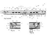
- FIG. 3a a cross-section of the apparatus 4 is shown, as seen along section A-A of Fig. 2 .
- the apparatus 4 has a number of components and/or compartments that are arranged in the direction of depth D.
- the apparatus 4 first comprises the panel 101 that defines the touch surface 102.
- the panel 101 is arranged on the elongated members 51-54 which thus support the panel 101 around its periphery. This means that the panel 101 may be mounted on the frame structure 50.
- the panel 101 forms a structural compartment that may be referred to as a panel compartment 10, which is defined by the boundaries of the panel 101.
- a display 201 is arranged, in the direction of depth D, behind the panel 101 and is configured to present an image that may be viewed through the panel 101.
- the display 201 and the presentation of an image are per se implemented according to known techniques and standards, and basically any type of display or screen may be used, including but not limited to an LCD (Liquid Crystal Display), a plasma display, and an OLED (Organic Light-Emitting Diode) display.
- the display 201 forms a structural compartment that may be referred to as a display compartment 20, which is defined by the boundaries of the display 201.
- the display 201 is mounted on the frame structure 50, either directly on the elongated members 51-54 or via support members, such as support member 203, which connect the display 201 to the peripheral frame structure 50.
- a light generation compartment 31 is arranged behind the display 201 as seen in the direction of depth D.
- the light generation compartment 31, which is also referred to as a "first compartment", comprises a light emitter arrangement 310.
- the light emitter arrangement 310 is configured to emit light 5 to be introduced into the panel 101 for propagation by internal reflections in the panel 101.
- a light detection compartment 32 is arranged behind the display 201 as seen in the direction of depth D.
- the light detection compartment 32 which is also referred to as a "second compartment", comprises a light detection arrangement 320.
- the light detection arrangement 320 is configured to receive light that has propagated in the panel 101 by internal reflections.
- the first compartment 31 is arranged behind the second compartment 32 as seen in the direction of depth D. This relative arrangement of the compartments 31, 32 may be advantageous in that e.g. access and any required adjustment of the light emitter arrangement 310 may be more efficiently facilitated.
- the light emitter arrangement 310 may include one or more radiation sources that emit light in the form of one or more beams.
- the radiation source(s) may be any type of device capable of emitting radiation in a desired wavelength range, such as a diode laser, a vertical-cavity surface-emitting laser, or alternatively a light-emitting diode (LED), an incandescent lamp, a halogen lamp, etc.
- the light emitter arrangement 310 is typically configured to generate the light 5 as one or more sheets that extend in a geometric plane perpendicular to the surface normal N and within the first compartment 31.
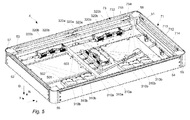
- the light emitter arrangement 310 comprises a set of scanner modules 310a, 310b.
- Each scanner module is a unitary component that includes at least one movable deflection element (not shown) which is controllable to deflect (scan) a beam of light from a radiation source (not shown) in a desired direction around an axis of rotation.
- the radiation source may be, and typically is, included in the scanner module 310a, 310b.
- Each scanner module 310a, 310b thus generates an angular scan of a beam of light within the first compartment 31.
- each such angular scan is indicated by an arched arrow between dotted lines representing the start and end locations of the angularly swept beam 5.
- reference numeral 501 indicates an angular scan between dotted lines 502 and 503.
- the scanner modules 310a are arranged to sweep beams in the y direction, and the scanner modules 310b are arranged to sweep beams in the x direction.
- the scanner modules 310a are arranged at a center of the apparatus 4, behind a central portion of the panel 101.
- the scanner modules 310b are however not centered, but arranged closer to the fourth elongated member 54 than to the third elongated member 53.
- the light detection arrangement 320 may include one or more light detectors, which may be any type of sensor capable of measuring the energy of incident light. Such sensors include e.g. optical detectors, photoresistors, photovoltaic cells, photodiodes, reverse-biased LEDs acting as photodiodes, charge-coupled devices, etc.
- the light detection arrangement comprises nine light detectors 320a, 320b. As will be described in further detail below, each light detector 320a, 320b is arranged to receive a respective sheet of light, when the sheet of light has propagated through the panel 101 (see Fig. 3a ). The sheets of light have an extension in a geometric plane perpendicular to the surface normal N within the second compartment 32. For reasons of clarity of presentation, these sheets of light are not indicated in Fig. 5 .
- the light detectors 320a are arranged to receive beams swept in the y direction, and the light detectors 320b are arranged to receive beams swept in the x direction.
- the light detectors 320a are arranged at a center of the apparatus 4, behind the central portion of the panel 101.
- the light detectors 320b are however not centered, but arranged closer to the third elongated member 53 than to the fourth elongated member 54.
- the apparatus 4 For allowing the sheets of light 5 generated by the light emitter arrangement 310 to be introduced into the panel 101 the apparatus 4 includes a first redirecting arrangement 71.
- the first redirecting arrangement 71 is mounted on the first elongated member 51 such that it introduces into the panel 101 light 5 that is emitted from the light emitter arrangement 310.
- the first redirecting arrangement 71 comprises a Fresnel lens 714, a first mirror 712 and a second mirror 713.
- the Fresnel lens 714, the first mirror 712 and the second mirror 713 are all elongated components that are mounted on and extend along the first elongated member 51.
- the Fresnel lens 714 is arranged to be swept by the beams of light from the scanner modules 310a. After passing the Fresnel lens 714, each angularly swept beam is converted (re-directed) into an output beam with an essentially invariant main direction along the Fresnel lens 714. In other words, an input beam which is swept angularly in one geometric plane along the Fresnel lens is converted into an output beam which is translated in the same geometric plane with an essentially fixed main direction beam (denoted "fixed-direction beam” in the following). Furthermore, the Fresnel lens 714 is configured to impart different main directions to the beams from the different scanner modules 310a. Further details on the generation and use of such fixed-direction beams are found in W02010/006882 and WO2010/006886 , in particular with reference to the beam arrangements denoted "v-scan" and " ⁇ -scan" therein.
- the Fresnel lens 714 and the first mirror 712 are arranged essentially level with the first compartment 31.
- the first mirror 712 is inclined in relation to the light from the Fresnel lens 714, such that the light is folded towards the second mirror 713.
- the second mirror 713 is closer to the panel 101 and is inclined such that the light from the first mirror 712 is folded again in a direction towards an incoupling site 105 on the panel 101, which thereby introduces the light into the panel 101.
- the incoupling site 105 typically comprises one or more incoupling structures (not shown), which may be of any conventional type, e.g. as disclosed in WO2010/006882 , WO2010/006885 and WO2010/006886 .
- the incoupling site 105 extends along the panel 101 in a direction parallel with the first elongated member 51.
- the elongated member 51 defines a common mounting part for the different components 712, 713, 714 of the redirecting arrangement 71.
- the provision of such a common mounting structure serves to limit the chain of tolerances between the components 712, 713, 714 that condition the beams of light before they are coupled into the panel 101. Limiting the chain of tolerances enables a predictable performance of the redirecting arrangement 71.
- the chain of tolerances may be further contained by also mounting the panel 101 on the frame structure 50, as in the illustrated embodiment.
- the use of the frame structure 50 as a common mounting part also serves to facilitate assembly of the apparatus 4, in particular the mounting of the redirecting arrangement 71.
- the light introduced via the incoupling site 105 propagates by total internal reflection (TIR) within the panel 101.
- TIR total internal reflection
- the propagation of light 5 by TIR is sustained as long as the light 5 is injected into the panel 101 at an angle to the surface normal N which is larger than the critical angle at the incoupling site 105 of the panel 101.
- the touch surface 102 allows the light 5 to interact with the touching object 2, and at the location 3 of the touch, part of the light 5 may be scattered by the object 2, part of the light 5 may be absorbed by the object 2 and part of the light 5 may continue to propagate in the panel 101 in its original direction in the panel 101.
- the interaction between the touching object 2 and the touch surface 102 is typically defined by the area of contact between the object 2 and the touch surface 102, and results in the mentioned interaction between the object 2 and the propagating light 5.
- the interaction between the object 2 and the light 5 may involve so-called frustrated total internal reflection (FTIR), in which energy of the light 5 is dissipated into the object 2 from an evanescent wave formed by the propagating light 5, provided that the object 2 has a higher refractive index than the material surrounding the touch surface 102 and is placed within less than several wavelengths distance from the touch surface 102.
- FTIR frustrated total internal reflection
- the apparatus 4 has a second redirecting arrangement 72 that receives light 5 coupled out of the panel 101.
- the second redirecting arrangement 72 is arranged at the second elongated member 52, i.e. at a side of the panel 101 that is opposite a side at which the first redirecting arrangement 71 is arranged.
- the second redirecting arrangement 72 is mounted on the second elongated member 52 and comprises a Fresnel lens 724, a first mirror 722 and a second mirror 723.
- the Fresnel lens 724, the first mirror 722 and the second mirror 723 are elongated components that are mounted on and extend along the second elongated member 52.
- the light 5 is coupled out of the panel 101, i.e. exits the panel 101, via an outcoupling site 106 on the panel 101.
- the outcoupling site 106 is opposite the touch surface 102.
- the outcoupling site 106 extends along the panel 101 in a direction parallel with the second elongated member 52 and comprises an outcoupling structure (not shown) that may structurally correspond to the incoupling structure of the incoupling site 105.
- the first mirror 722 is inclined in relation to the touch surface 102, such that the light 5 is folded towards the second mirror 723.
- the second mirror 723 is further away from the panel 101 than the first mirror 722 and is inclined such that the light from the first mirror 712 is folded again in a direction into the second compartment 32.
- the Fresnel lens 724 is arranged to redirect the light onto the light detection arrangement 320.
- the Fresnel lens 724 and the second mirror 723 are arranged essentially level with the second compartment 32.
- the function of the Fresnel lens 724 is to direct each swept fixed-direction beam onto a respective light detector 320a, shown in Fig. 5 .
- the respective fixed-direction beam is swept along the Fresnel lens 724 and thereby redirected onto one of the light detectors 320a, which generate signals that represent the energy (or equivalently, the power or intensity) of the received light as a function of time, for each of the beams generated by the scanner modules 310a.
- apparatus 4 has a third redirecting arrangement 73 that comprises a Fresnel lens 734, a first mirror 732 and a second mirror 733 that are mounted on the third elongated member 53.
- the Fresnel lens 734, the first mirror 732 and the second mirror 733 of the third redirecting arrangement 73 are elongated and extend along the third elongated member 53.
- the apparatus 4 has a fourth redirecting arrangement 74 that comprises a Fresnel lens 744, a first mirror 742 and second mirror 743 that are mounted on the fourth elongated member 54.
- the Fresnel lens 744, the first mirror 742 and the second mirror 743 of the fourth redirecting arrangement 74 are elongated and extend along the fourth elongated member 54.
- the light emitter arrangement 310 is operable to generate sheets of light also in a direction towards the third redirecting arrangement 73.
- the generated sheets of light are by the third redirecting arrangement 73 redirected and folded so as to be coupled into the panel 101 in which the sheets of light propagate by TIR towards an edge of the panel 101 at the fourth elongated member 54.
- the propagated sheets of light are coupled out of the panel 101 and then folded and redirected by the fourth redirecting arrangement 74 in a direction towards the light detection arrangement 320.
- the light detection arrangement 320 then generates signals that represent the energy of the received light from each sheet of light as a function of time.
- the third redirecting arrangement 73 is similar to the first redirecting arrangement 71 and the fourth redirecting arrangement 74 is similar to the second redirecting arrangement 72.
- six scanner modules 310b are arranged to generate a respective angular scan of a beam of light in the x direction within the first compartment 31.
- the six scanner modules 310b are arranged in two groups, with each scanner module 310b in the left-hand and right-hand groups in Fig. 5 being arranged to generate an angular scan along the left-hand and right-hand portion of the third redirecting arrangement 73, respectively, as indicated by the dotted lines.
- the light from each group of scanner modules 310b results in three swept fixed-direction beams, which after propagating through the panel are directed onto a respective light detector 320b.
- the two groups of scanner modules 310b are operable to jointly generate three full beam sweeps across the panel in the x direction, by each group sweeping three beams of light inside the panel along approximately half of the panel in the x direction.
- the apparatus 4 has a power supply unit 60 arranged, in the direction of depth D, behind the first and second compartments 31, 32.
- the power supply unit 60 comprises a transformer 61 and an electronics module 62 that feed the light emitter arrangement 310, the light detection arrangement 320 and any other power requiring component of the apparatus 4 with an electrical current.
- the light detection arrangement 320 measures the energy of all light it receives and outputs one or more signals that reflect the measured energy. Conventional techniques are then used for determining the location 3 of the touch on the touch surface 102. The determined location 3 may thereafter be used for any suitable application that employs the display 201 for interaction with a user. Examples of suitable techniques for determining the location 3 may be found in e.g.
- the scanner modules 310a are controlled to emit light in form of three beams that are repeatedly swept or scanned across the first redirecting arrangement 71.
- the three beams are coupled into the panel 101, propagate in the panel 101 and are coupled out at the second redirecting arrangement 72 to be redirected onto the light detectors 320a.
- the scanner modules 310b are controlled to emit light in form of six beams that are repeatedly swept or scanned across the third redirecting arrangement 73.
- three of the six beams are swept across half of the third redirecting arrangement 73 while the other three beams are swept across the other half of the third redirecting arrangement 73.
- the beams from the scanner modules 310b are coupled into the panel 101, propagate in the panel 101 and are coupled out at the fourth redirecting arrangement 74 to be redirected onto the light detectors 320b. It should be realized that the scanner modules 310a, 310b may be activated concurrently or sequentially, or in any combination thereof.
- the light emitter arrangement 310 may be given a layout which is essentially independent of the layout of the light detection arrangement 320.
- the placement of the scanner modules 310a, 320a may be optimized separately from the placement of the light detectors 310b, 320b.
- first and second compartments 31, 32 also enables optical separation of the first and second compartments 31, 32. This means that light from the light emitter arrangement 310 is prevented from reaching the light detection arrangement 320 without first having propagated in the panel 101.
- the light detection arrangement 320 may generate a signal with less noise since it receives less stray light from the light emitter arrangement 310. This may be advantageous e.g. in that the apparatus 4 becomes less dependent on signal processing algorithms that require significant calculation efforts.
- the first compartment 31 is arranged, in the direction of depth D, at a different distance from the display 201 than the second compartment 32, such that the compartments 31, 32 are spatially separated in the direction of depth D.
- Such an arrangement of the compartments 31, 32 maximizes the available space for the light emitter arrangement 310 and for the light detection arrangement 320, respectively. It should be realized that the compartments 31, 32 should provide unobstructed beam paths for all sheets of light that are generated and received by the light emitter arrangement 310 and the light detection arrangement 320, respectively.
- the freedom for defining the layout of the light emitter arrangement 310 and the light detection arrangement 320 is increased, which in turn may enable a design of the apparatus that provides improved performance, e.g. with respect to the number of simultaneous touches that may be detected, the detection speed, the manufacturing cost, the required processing power for touch determination, the precision of the determined touch locations, the ability to produce a signal with less noise, etc.
- the second compartment 32 is located closer to the display 201 than the first compartment 31.
- the first compartment 31 is instead located closer to the display 201 than the second compartment 32.
- the first compartment 31 may have a first planar extension while the second compartment 32 may have a second planar extension.
- each of the first and second compartments 31, 32 has an extension in the direction of depth D and a planar extension that is parallel with the touch surface 102.
- the first compartment 31 is structurally separated from the second compartment 32, i.e. the compartments are not virtual or merely functional compartments.
- the apparatus comprises a sheet 410 (see Figs 3a and 4 ) which is arranged between the first compartment 31 and the second compartment 32.
- the sheet 410 forms a structural compartment that may be referred to as a sheet compartment 40, which compartment 40 is defined by the boundaries of the sheet 410.
- the sheet 410 may be made of metal and may have a surface that is parallel with the touch surface 102.
- the sheet 410 may have a planar extension in between the first compartment 31 and the second compartment 32, so as to efficiently prevent light emitted from the light emitter arrangement 310 from entering the light detection arrangement 320 unless the light 5 has first propagated in the panel 101.
- the sheet 410 may have openings (not shown), such as cable penetrations or ducts, as long as the openings do not allow any light to pass through the sheet 410 and enter the light detection arrangement 320.
- the sheet 410 is thus a light blocking element between the first and second compartments 31, 32.
- the apparatus 4 To properly seal the apparatus 4 it comprises a rear plate 411 which is, as seen in the direction of depth D, arranged behind the first compartment 31.
- the rear plate 411 may however be part of the compartment that is furthest from the touch surface 102, i.e. the first compartment 31 in the illustrated example.
- both the panel 101 and the display 201 are supported by the elongated members 51, 52, 53, 54, for example by a protrusion 539 of the third elongated member 53 and by a protrusion 549 of the fourth elongated member 54.
- the first elongated member 51 and the second elongated member 52 may have similar protrusions.
- a suitable adhesive may be used to fix the panel 101 to the supports.
- Various kinds of screw arrangements may be used to secure the display 201.
- the display 201 may also be supported by a centre support 59 that is located, in the direction of depth D, behind a central portion 103 of the display 201.
- the centre support 59 is in contact with the display 201 and may extend through the first and second compartments 31, 32 and to the rear plate 411.
- the light detectors 320a and the scanner modules 310a described in connection with Fig. 5 may be arranged on different sides of the centre support 59.
- the compartments 31, 32 should be optically sealed at locations where they intersect with the centre support 59, such that light is prevented from passing directly from the first compartment 31 to the light detection arrangement 320 in the second compartment 32.
- the centre support 59 may include a channel 598 for conveying air to the display 201 for the purpose of cooling the display 201.
- a fan may for this purpose be installed at an inlet of the channel 598 together with a filter that prevents dust from entering the channel 598 from a surrounding environment. Instead of using a fan, the air may self-circulate through the channel 598.
- the air is typically conveyed to the back of the display 201 and may exit the apparatus 4 through small openings or vents (not shown) in the apparatus 4.
- a vent compartment 90 may be arranged between the display compartment 20 and the second compartment 32. Both the first compartment 31 and the second compartment 32 are optically separated from the vent compartment 90, such that light from the channel 598 or any other vent opening is prevented from being coupled into the panel 101 or directly reach the second compartment 32.
- One or more of the elongated members 51, 52, 53, 54 may comprise a channel that functionally corresponds to the channel 598 of the centre support 59, such as channels 538 and 548 in the third elongated member 53 and fourth elongated member 54, respectively.
- Such channels may be implemented with or without the use of the centre support 59, or the channel 598 in the centre support 59.
- any of the channels of the centre support 59 and elongated members 51, 52, 53, 54 may be used for installing electrical cables from the power supply unit 60 to components of the apparatus 4 that require electrical current for their operation.
- an arrangement of a component/compartment behind another component/compartment may be seen as an arrangement “after” or “underneath” that component/compartment.
- the individual sheets may be generated by non-swept beams that diverge in the geometric plane away from light sources in the first compartment 31 so as to impinge on a Fresnel lens that redirects the light rays of the diverging beam into a given main direction (i.e. a collimated sheet).
- a Fresnel lens that redirects the light rays of the diverging beam into a given main direction (i.e. a collimated sheet).
Landscapes
- Engineering & Computer Science (AREA)
- General Engineering & Computer Science (AREA)
- Theoretical Computer Science (AREA)
- Human Computer Interaction (AREA)
- Physics & Mathematics (AREA)
- General Physics & Mathematics (AREA)
- Position Input By Displaying (AREA)
- Switches Operated By Changes In Physical Conditions (AREA)
Applications Claiming Priority (1)
| Application Number | Priority Date | Filing Date | Title |
|---|---|---|---|
| SE1051334 | 2010-12-16 |
Publications (2)
| Publication Number | Publication Date |
|---|---|
| EP2466428A2 true EP2466428A2 (de) | 2012-06-20 |
| EP2466428A3 EP2466428A3 (de) | 2015-07-29 |
Family
ID=45406447
Family Applications (1)
| Application Number | Title | Priority Date | Filing Date |
|---|---|---|---|
| EP11193198.6A Withdrawn EP2466428A3 (de) | 2010-12-16 | 2011-12-13 | Berührungsvorrichtung mit getrennten Einsätzen |
Country Status (2)
| Country | Link |
|---|---|
| US (1) | US8872801B2 (de) |
| EP (1) | EP2466428A3 (de) |
Cited By (8)
| Publication number | Priority date | Publication date | Assignee | Title |
|---|---|---|---|---|
| US20210173514A1 (en) * | 2016-12-07 | 2021-06-10 | Flatfrog Laboratories Ab | Touch device |
| US11893189B2 (en) | 2020-02-10 | 2024-02-06 | Flatfrog Laboratories Ab | Touch-sensing apparatus |
| US12056316B2 (en) | 2019-11-25 | 2024-08-06 | Flatfrog Laboratories Ab | Touch-sensing apparatus |
| US12055969B2 (en) | 2018-10-20 | 2024-08-06 | Flatfrog Laboratories Ab | Frame for a touch-sensitive device and tool therefor |
| US12086362B2 (en) | 2017-09-01 | 2024-09-10 | Flatfrog Laboratories Ab | Optical component |
| US12175044B2 (en) | 2017-02-06 | 2024-12-24 | Flatfrog Laboratories Ab | Optical coupling in touch-sensing systems |
| US12282653B2 (en) | 2020-02-08 | 2025-04-22 | Flatfrog Laboratories Ab | Touch apparatus with low latency interactions |
| US12524116B2 (en) | 2018-03-05 | 2026-01-13 | Flatfrog Laboratories Ab | Detection line broadening |
Families Citing this family (22)
| Publication number | Priority date | Publication date | Assignee | Title |
|---|---|---|---|---|
| US9092092B2 (en) | 2008-08-07 | 2015-07-28 | Rapt Ip Limited | Detecting multitouch events in an optical touch-sensitive device using touch event templates |
| US9063615B2 (en) | 2008-08-07 | 2015-06-23 | Rapt Ip Limited | Detecting multitouch events in an optical touch-sensitive device using line images |
| SE533704C2 (sv) | 2008-12-05 | 2010-12-07 | Flatfrog Lab Ab | Pekkänslig apparat och förfarande för drivning av densamma |
| TWI497376B (zh) | 2011-07-22 | 2015-08-21 | Rapt Ip Ltd | 在光學觸敏裝置中使用之光學耦合器總成 |
| US10168835B2 (en) | 2012-05-23 | 2019-01-01 | Flatfrog Laboratories Ab | Spatial resolution in touch displays |
| US9524060B2 (en) | 2012-07-13 | 2016-12-20 | Rapt Ip Limited | Low power operation of an optical touch-sensitive device for detecting multitouch events |
| US9405382B2 (en) | 2012-07-24 | 2016-08-02 | Rapt Ip Limited | Augmented optical waveguide for use in an optical touch sensitive device |
| US9785287B2 (en) * | 2012-12-17 | 2017-10-10 | Flatfrog Laboratories Ab | Optical coupling in touch-sensing systems |
| US10019113B2 (en) | 2013-04-11 | 2018-07-10 | Flatfrog Laboratories Ab | Tomographic processing for touch detection |
| US9874978B2 (en) | 2013-07-12 | 2018-01-23 | Flatfrog Laboratories Ab | Partial detect mode |
| US10126882B2 (en) | 2014-01-16 | 2018-11-13 | Flatfrog Laboratories Ab | TIR-based optical touch systems of projection-type |
| US10146376B2 (en) | 2014-01-16 | 2018-12-04 | Flatfrog Laboratories Ab | Light coupling in TIR-based optical touch systems |
| WO2015199602A1 (en) | 2014-06-27 | 2015-12-30 | Flatfrog Laboratories Ab | Detection of surface contamination |
| EP3250993B1 (de) | 2015-01-28 | 2019-09-04 | FlatFrog Laboratories AB | Dynamische berührungsquarantänerahmen |
| US10318074B2 (en) | 2015-01-30 | 2019-06-11 | Flatfrog Laboratories Ab | Touch-sensing OLED display with tilted emitters |
| EP3537269A1 (de) | 2015-02-09 | 2019-09-11 | FlatFrog Laboratories AB | Optisches berührungssystem |
| CN107250855A (zh) | 2015-03-02 | 2017-10-13 | 平蛙实验室股份公司 | 用于光耦合的光学部件 |
| EP3387516B1 (de) | 2015-12-09 | 2022-04-20 | FlatFrog Laboratories AB | Verbesserte stiftidentifizierung |
| WO2018096430A1 (en) | 2016-11-24 | 2018-05-31 | Flatfrog Laboratories Ab | Automatic optimisation of touch signal |
| WO2018174786A1 (en) | 2017-03-22 | 2018-09-27 | Flatfrog Laboratories | Pen differentiation for touch displays |
| WO2018182476A1 (en) | 2017-03-28 | 2018-10-04 | Flatfrog Laboratories Ab | Touch sensing apparatus and method for assembly |
| WO2020153890A1 (en) | 2019-01-25 | 2020-07-30 | Flatfrog Laboratories Ab | A videoconferencing terminal and method of operating the same |
Citations (15)
| Publication number | Priority date | Publication date | Assignee | Title |
|---|---|---|---|---|
| US6972753B1 (en) | 1998-10-02 | 2005-12-06 | Semiconductor Energy Laboratory Co., Ltd. | Touch panel, display device provided with touch panel and electronic equipment provided with display device |
| US20060114237A1 (en) | 2004-11-17 | 2006-06-01 | Crockett Timothy W | Method and system for providing a frustrated total internal reflection touch interface |
| US20070075648A1 (en) | 2005-10-03 | 2007-04-05 | Blythe Michael M | Reflecting light |
| US7432893B2 (en) | 2003-06-14 | 2008-10-07 | Massachusetts Institute Of Technology | Input device based on frustrated total internal reflection |
| WO2009048365A1 (en) | 2007-10-10 | 2009-04-16 | Flatfrog Laboratories Ab | A touch pad and a method of operating the touch pad |
| US20090153519A1 (en) | 2007-12-17 | 2009-06-18 | Suarez Rovere Victor Manuel | Method and apparatus for tomographic touch imaging and interactive system using same |
| WO2010006886A2 (en) | 2008-06-23 | 2010-01-21 | Flatfrog Laboratories Ab | Determining the location of one or more objects on a touch surface |
| WO2010006882A2 (en) | 2008-06-23 | 2010-01-21 | Flatfrog Laboratories Ab | Detecting the locations of a plurality of objects on a touch surface |
| WO2010006883A2 (en) | 2008-06-23 | 2010-01-21 | Flatfrog Laboratories Ab | Determining the location of one or more objects on a touch surface |
| WO2010006885A2 (en) | 2008-06-23 | 2010-01-21 | Flatfrog Laboratories Ab | Detecting the location of an object on a touch surface |
| WO2010006884A2 (en) | 2008-06-23 | 2010-01-21 | Flatfrog Laboratories Ab | Detecting the location of an object on a touch surface |
| WO2010134865A1 (en) | 2009-05-18 | 2010-11-25 | Flatfrog Laboratories Ab | Determining the location of an object on a touch surface |
| WO2011049511A1 (en) | 2009-10-19 | 2011-04-28 | Flatfrog Laboratories Ab | Extracting touch data that represents one or more objects on a touch surface |
| WO2011049513A1 (en) | 2009-10-19 | 2011-04-28 | Flatfrog Laboratories Ab | Determining touch data for one or more objects on a touch surface |
| WO2011139213A1 (en) | 2010-05-03 | 2011-11-10 | Flatfrog Laboratories Ab | Touch determination by tomographic reconstruction |
Family Cites Families (16)
| Publication number | Priority date | Publication date | Assignee | Title |
|---|---|---|---|---|
| US3673327A (en) | 1970-11-02 | 1972-06-27 | Atomic Energy Commission | Touch actuable data input panel assembly |
| JPH0325220Y2 (de) * | 1985-02-15 | 1991-05-31 | ||
| JPH0325219Y2 (de) * | 1985-02-15 | 1991-05-31 | ||
| JP2001183987A (ja) * | 1999-12-27 | 2001-07-06 | Pioneer Electronic Corp | 冷却構造およびこれを用いたディスプレイ装置 |
| US20050122308A1 (en) | 2002-05-28 | 2005-06-09 | Matthew Bell | Self-contained interactive video display system |
| KR100534968B1 (ko) * | 2003-09-16 | 2005-12-08 | 현대자동차주식회사 | 전자소자의 냉각구조 |
| US20060158437A1 (en) * | 2005-01-20 | 2006-07-20 | Blythe Michael M | Display device |
| US8077147B2 (en) * | 2005-12-30 | 2011-12-13 | Apple Inc. | Mouse with optical sensing surface |
| JP2008096523A (ja) * | 2006-10-06 | 2008-04-24 | Hitachi Displays Ltd | 表示装置 |
| US7924272B2 (en) * | 2006-11-27 | 2011-04-12 | Microsoft Corporation | Infrared sensor integrated in a touch panel |
| EP2156276A4 (de) * | 2007-05-11 | 2011-12-07 | Rpo Pty Ltd | Durchlässiger körper |
| US8184101B2 (en) | 2007-10-03 | 2012-05-22 | Microsoft Corporation | Detecting touch on a surface via a scanning laser |
| JP5082779B2 (ja) * | 2007-11-07 | 2012-11-28 | 株式会社日立製作所 | 平面型表示装置 |
| JP5162706B2 (ja) * | 2008-09-26 | 2013-03-13 | ヒューレット−パッカード デベロップメント カンパニー エル.ピー. | 撹乱光を使用したタッチロケーションの決定 |
| US8093545B2 (en) * | 2008-09-26 | 2012-01-10 | Avago Technologies Ecbu Ip (Singapore) Pte. Ltd. | Lensless user input device with optical interference based on diffraction with a small aperture |
| US8816963B2 (en) * | 2010-12-13 | 2014-08-26 | Sae Magnetics (H.K.) Ltd. | Optical navigation module and mobile electronic appliance using optical navigation module |
-
2011
- 2011-12-13 EP EP11193198.6A patent/EP2466428A3/de not_active Withdrawn
- 2011-12-14 US US13/325,877 patent/US8872801B2/en not_active Expired - Fee Related
Patent Citations (15)
| Publication number | Priority date | Publication date | Assignee | Title |
|---|---|---|---|---|
| US6972753B1 (en) | 1998-10-02 | 2005-12-06 | Semiconductor Energy Laboratory Co., Ltd. | Touch panel, display device provided with touch panel and electronic equipment provided with display device |
| US7432893B2 (en) | 2003-06-14 | 2008-10-07 | Massachusetts Institute Of Technology | Input device based on frustrated total internal reflection |
| US20060114237A1 (en) | 2004-11-17 | 2006-06-01 | Crockett Timothy W | Method and system for providing a frustrated total internal reflection touch interface |
| US20070075648A1 (en) | 2005-10-03 | 2007-04-05 | Blythe Michael M | Reflecting light |
| WO2009048365A1 (en) | 2007-10-10 | 2009-04-16 | Flatfrog Laboratories Ab | A touch pad and a method of operating the touch pad |
| US20090153519A1 (en) | 2007-12-17 | 2009-06-18 | Suarez Rovere Victor Manuel | Method and apparatus for tomographic touch imaging and interactive system using same |
| WO2010006886A2 (en) | 2008-06-23 | 2010-01-21 | Flatfrog Laboratories Ab | Determining the location of one or more objects on a touch surface |
| WO2010006882A2 (en) | 2008-06-23 | 2010-01-21 | Flatfrog Laboratories Ab | Detecting the locations of a plurality of objects on a touch surface |
| WO2010006883A2 (en) | 2008-06-23 | 2010-01-21 | Flatfrog Laboratories Ab | Determining the location of one or more objects on a touch surface |
| WO2010006885A2 (en) | 2008-06-23 | 2010-01-21 | Flatfrog Laboratories Ab | Detecting the location of an object on a touch surface |
| WO2010006884A2 (en) | 2008-06-23 | 2010-01-21 | Flatfrog Laboratories Ab | Detecting the location of an object on a touch surface |
| WO2010134865A1 (en) | 2009-05-18 | 2010-11-25 | Flatfrog Laboratories Ab | Determining the location of an object on a touch surface |
| WO2011049511A1 (en) | 2009-10-19 | 2011-04-28 | Flatfrog Laboratories Ab | Extracting touch data that represents one or more objects on a touch surface |
| WO2011049513A1 (en) | 2009-10-19 | 2011-04-28 | Flatfrog Laboratories Ab | Determining touch data for one or more objects on a touch surface |
| WO2011139213A1 (en) | 2010-05-03 | 2011-11-10 | Flatfrog Laboratories Ab | Touch determination by tomographic reconstruction |
Cited By (13)
| Publication number | Priority date | Publication date | Assignee | Title |
|---|---|---|---|---|
| US11579731B2 (en) * | 2016-12-07 | 2023-02-14 | Flatfrog Laboratories Ab | Touch device |
| US12566525B2 (en) | 2016-12-07 | 2026-03-03 | Flatfrog Laboratories Ab | Touch device |
| US20210173514A1 (en) * | 2016-12-07 | 2021-06-10 | Flatfrog Laboratories Ab | Touch device |
| US12189906B2 (en) | 2016-12-07 | 2025-01-07 | Flatfrog Laboratories Ab | Touch device |
| US12524117B2 (en) | 2017-02-06 | 2026-01-13 | Flatfrog Laboratories Ab | Optical coupling in touch-sensing systems |
| US12175044B2 (en) | 2017-02-06 | 2024-12-24 | Flatfrog Laboratories Ab | Optical coupling in touch-sensing systems |
| US12086362B2 (en) | 2017-09-01 | 2024-09-10 | Flatfrog Laboratories Ab | Optical component |
| US12524116B2 (en) | 2018-03-05 | 2026-01-13 | Flatfrog Laboratories Ab | Detection line broadening |
| US12055969B2 (en) | 2018-10-20 | 2024-08-06 | Flatfrog Laboratories Ab | Frame for a touch-sensitive device and tool therefor |
| US12056316B2 (en) | 2019-11-25 | 2024-08-06 | Flatfrog Laboratories Ab | Touch-sensing apparatus |
| US12461630B2 (en) | 2019-11-25 | 2025-11-04 | Flatfrog Laboratories Ab | Touch-sensing apparatus |
| US12282653B2 (en) | 2020-02-08 | 2025-04-22 | Flatfrog Laboratories Ab | Touch apparatus with low latency interactions |
| US11893189B2 (en) | 2020-02-10 | 2024-02-06 | Flatfrog Laboratories Ab | Touch-sensing apparatus |
Also Published As
| Publication number | Publication date |
|---|---|
| EP2466428A3 (de) | 2015-07-29 |
| US8872801B2 (en) | 2014-10-28 |
| US20120154338A1 (en) | 2012-06-21 |
Similar Documents
| Publication | Publication Date | Title |
|---|---|---|
| US8872801B2 (en) | Touch apparatus with separated compartments | |
| US9857917B2 (en) | Optical coupling of light into touch-sensing systems | |
| US9857916B2 (en) | Optical coupling in touch-sensing systems using diffusively transmitting element | |
| US9366752B2 (en) | Proximity sensor with asymmetric optical element | |
| CN101669088B (zh) | 用于检测多个触摸的触摸屏 | |
| US9983027B2 (en) | Proximity sensor module with light reflector | |
| US10268319B2 (en) | Edge-coupled touch-sensitive apparatus | |
| US8872098B2 (en) | Scanning FTIR systems for touch detection | |
| US8773399B2 (en) | Touch display device | |
| US20080007541A1 (en) | Optical touchpad system and waveguide for use therein | |
| WO2010006885A2 (en) | Detecting the location of an object on a touch surface | |
| WO2013191638A1 (en) | Optical coupling in touch-sensing systems using diffusively reflecting element | |
| EP2356551A1 (de) | Integrierte berührungsempfindliche anzeige und betriebsverfahren dafür | |
| KR20110032640A (ko) | 멀티 터치 인식 디스플레이 장치 | |
| CN101807131B (zh) | 侦测模块及包含此侦测模块的光学侦测系统 | |
| KR20120073763A (ko) | 표시장치 | |
| TWI410685B (zh) | 波導模組、光學觸控模組以及提高光學觸控模組之訊雜比之方法 | |
| JP2013149231A (ja) | 入力システム | |
| JP2013250817A (ja) | 座標入力装置及び座標入力システム | |
| JPWO2011052379A1 (ja) | 導光ユニット及び入力装置 | |
| JP6599631B2 (ja) | タッチパネル装置 | |
| JP2019204559A (ja) | タッチパネル装置 | |
| JP2013250816A (ja) | 座標入力装置、及び座標入力システム | |
| CN111897162B (zh) | 光源组件、背光模组及显示装置 | |
| JP2013250814A (ja) | 座標入力装置、及び座標入力システム |
Legal Events
| Date | Code | Title | Description |
|---|---|---|---|
| PUAI | Public reference made under article 153(3) epc to a published international application that has entered the european phase |
Free format text: ORIGINAL CODE: 0009012 |
|
| AK | Designated contracting states |
Kind code of ref document: A2 Designated state(s): AL AT BE BG CH CY CZ DE DK EE ES FI FR GB GR HR HU IE IS IT LI LT LU LV MC MK MT NL NO PL PT RO RS SE SI SK SM TR |
|
| AX | Request for extension of the european patent |
Extension state: BA ME |
|
| PUAL | Search report despatched |
Free format text: ORIGINAL CODE: 0009013 |
|
| AK | Designated contracting states |
Kind code of ref document: A3 Designated state(s): AL AT BE BG CH CY CZ DE DK EE ES FI FR GB GR HR HU IE IS IT LI LT LU LV MC MK MT NL NO PL PT RO RS SE SI SK SM TR |
|
| AX | Request for extension of the european patent |
Extension state: BA ME |
|
| RIC1 | Information provided on ipc code assigned before grant |
Ipc: G06F 3/042 20060101AFI20150624BHEP |
|
| STAA | Information on the status of an ep patent application or granted ep patent |
Free format text: STATUS: THE APPLICATION IS DEEMED TO BE WITHDRAWN |
|
| 18D | Application deemed to be withdrawn |
Effective date: 20160130 |