EP2466549A1 - Fahrzeuggerät für ein Strassenmautsystem - Google Patents
Fahrzeuggerät für ein Strassenmautsystem Download PDFInfo
- Publication number
- EP2466549A1 EP2466549A1 EP10450193A EP10450193A EP2466549A1 EP 2466549 A1 EP2466549 A1 EP 2466549A1 EP 10450193 A EP10450193 A EP 10450193A EP 10450193 A EP10450193 A EP 10450193A EP 2466549 A1 EP2466549 A1 EP 2466549A1
- Authority
- EP
- European Patent Office
- Prior art keywords
- antenna
- radio communication
- vehicle device
- toll
- beacons
- Prior art date
- Legal status (The legal status is an assumption and is not a legal conclusion. Google has not performed a legal analysis and makes no representation as to the accuracy of the status listed.)
- Granted
Links
- 238000011156 evaluation Methods 0.000 claims abstract description 19
- 101001093748 Homo sapiens Phosphatidylinositol N-acetylglucosaminyltransferase subunit P Proteins 0.000 claims description 10
- 238000001514 detection method Methods 0.000 claims description 2
- 238000009434 installation Methods 0.000 description 2
- 238000005284 basis set Methods 0.000 description 1
- 230000005859 cell recognition Effects 0.000 description 1
- 230000001413 cellular effect Effects 0.000 description 1
- 230000001419 dependent effect Effects 0.000 description 1
- 238000010586 diagram Methods 0.000 description 1
- 230000002349 favourable effect Effects 0.000 description 1
- 230000004807 localization Effects 0.000 description 1
- 238000012986 modification Methods 0.000 description 1
- 230000004048 modification Effects 0.000 description 1
- 230000000737 periodic effect Effects 0.000 description 1
- 230000005855 radiation Effects 0.000 description 1
Images

Classifications
-
- G—PHYSICS
- G07—CHECKING-DEVICES
- G07B—TICKET-ISSUING APPARATUS; FARE-REGISTERING APPARATUS; FRANKING APPARATUS
- G07B15/00—Arrangements or apparatus for collecting fares, tolls or entrance fees at one or more control points
- G07B15/06—Arrangements for road pricing or congestion charging of vehicles or vehicle users, e.g. automatic toll systems
- G07B15/063—Arrangements for road pricing or congestion charging of vehicles or vehicle users, e.g. automatic toll systems using wireless information transmission between the vehicle and a fixed station
Definitions
- the present invention relates to a vehicle device for a road toll system, with a transceiver for short-range radio communication optionally with toll beacons or with respect to these deeper control beacons.
- Road toll systems with onboard units that work with roadside short range radio beacons allow locating the OBUs based on the beacon locations and their spatially limited radio coverage areas.
- OBUs onboard units
- local uses of the OBU can be charged, for example in the form of tolls, entrance fees or parking tolls.
- the shortest possible range of the radio communication is advantageous, which is only limited by the minimum time for a radio communication.
- OBUs are currently equipped with an upwardly radiating directional antenna, which cooperates with over the roadway arranged toll beacons in a narrow radio coverage area.
- the invention has for its object to provide a vehicle device for a road toll system, which overcomes the described problems of the prior art.
- a vehicle device of the aforementioned type which according to the invention is characterized in that the transceiver has an antenna system with at least two adjustable antenna characteristics, of which the first has a higher and the second a deeper radio coverage area with respect to the vehicle unit, wherein the vehicle unit is further adapted to set the first antenna in the radio communication with a toll beacon and the second antenna characteristic in the radio communication with a control beacon.
- an OBU with an adapting to the location and thus the function of their respective communication partner radio coverage area created:
- Verortungstician of usually stationary toll beacons is set upwards or obliquely upward-forward antenna radiation characteristic
- Control option by usually mobile control beacons of the surrounding flow traffic is set a lateral or "flatter”, preferably around laterally directed or omnidirectional antenna characteristics.
- the vehicle device has a device for determining its own position, a database with stored locations of toll beacons, as well as a connected to these two and the antenna system controlling evaluation, which, if the own position within a predetermined range to a stored location that sets the first antenna characteristic, and if not, adjusts the second antenna characteristic.
- the vehicle device can autonomously determine whether it is in the vicinity of a stationary toll beacon, and automatically align its antenna characteristics to it, while otherwise lapsing into an "ambient" mode easily accessible to control beacons from surrounding traffic flow or oncoming traffic.
- the OBU can determine its position in any manner known in the art.
- the position determining device is preferably a satellite navigation receiver, which gives the OBU the greatest possible independence.
- a road toll system has a relatively small, manageable number of fixed toll beacons, for example, about 2500 pieces in the Austrian DSRC road toll system.
- the places of toll banners are hardly changeable; Essentially, new beacons are only added to new or expanded toll infrastructure.
- the effort to maintain the database with the locations of the toll beacons is therefore very low in practice.
- the database may only be stored once upon delivery of an OBU.
- the database may be updatable via the transceiver from the toll beacons so that any changes can be incorporated into the OBUs themselves via the roadside infrastructure. Since such changes rarely occur, as discussed, the additional traffic in the road toll system is low.
- a second preferred embodiment of the invention is that the antenna system periodically alternates between the two antenna characteristics prior to the start of a radio communication and the vehicle unit has an evaluation device connected to the antenna system, by means of which the antenna characteristic present at the beginning of a radio communication can be detected, in order then to This radio communication set this antenna characteristics.
- the OBU recognizes on which "receive channel" - Which antenna characteristic - they receive a contact for a wireless communication, from which it can be deduced from which place the contact was made: If the wireless communication was initiated by a stationary tollbake, the contact will usually succeed if the OBU after upwardly directed antenna characteristic occupies; if the radio communication has been picked up by a mobile control beacon of the surrounding traffic, this will generally be successful if the OBU is taking on the deeper or flatter, more forward and / or side-facing antenna characteristics. In this way it is possible to indirectly conclude the location or the identity of the communication partner and thus set the correct antenna characteristic for the further radio communication.
- this functionality can be achieved with a further embodiment of the vehicle device, in which the antenna system for each antenna characteristic has its own parallel antenna and the vehicle device has an evaluation device connected thereto, by means of which the antenna which receives the beginning of a radio communication, is detectable to then to set this antenna for this radio communication.
- the OBU "hears" on which receive channel a contact is made, thus closing again on the location or the identity of its communication partner to adjust their antenna characteristics accordingly.
- the vehicle device has an evaluation device connected to the antenna system, by means of which an identifier of a toll beacon received as the beginning of a radio communication can be detected in order to set the first antenna characteristic in the case of detection for this radio communication.
- the OBU learns when contacting a toll or Kontrollbake of their identity and can on basis Set the appropriate antenna characteristics for this information.
- the said identifier is a BST message (beacon service table message) according to the DSRC standard, as they are the first contact of toll beacons DSRC standards.
- BST message may also wake an OBU from a low power standby mode, for example.
- the OBU is set to the second antenna characteristic before starting a radio communication in order to be readily addressable for control beacons at any time.
- the vehicle device of the invention is suitable for all types of road toll systems based on short-range radio beacons, for example according to the WLAN or WAVE standard. Its use is particularly favorable in a DSRC road toll system, in which case the transceiver is a DSRC transceiver, preferably according to the CEN or WAVE standard.
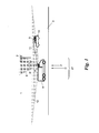
- a road toll system 1 includes a plurality of toll beacons 2 distributed over a geographical area, only one of which is shown as representative.
- the toll beacons 2 are each stationarily mounted on a road 3.
- the term "stationary” used here includes both permanently anchored and transportable toll bollards 2 set up only temporarily on a road 3. In each case, the location O of its installation in the road toll system 1 is known.
- the toll beacons 2 are short-range radio beacons, preferably according to the DSRC standard (dedicated short range communication standard), and serve to perform short-range or DSCR radio communications 4 with vehicle units 5 (onboard units, OBUs) of passing vehicles 6.
- the OBUs 5 in turn have short range or DSCR transceivers 7, which will be described later in more detail with reference to Fig. 2 be explained.
- tolling transactions are subsequently generated by the tolling beacons 2 and, for example, deposited via a data connection to a (not shown) control center of the road tolling system 1.
- the stationary toll beacons 2 are arranged next to or above the road 3 at a certain height, for example on a bridge supporting the road 3, a mast arranged next to the road 3 or the like.
- the transceiver 7 of an OBU 5 assumes a first antenna characteristic in a short-range radio communication 4 with a toll beacon 2, which is directed to an area 8 above the OBU 5.
- the region 8 is, for example, a cone-shaped or club-shaped upward or obliquely upward (“skyward”) or in particular obliquely forward and upward aligned transceiver region.
- this orientation of the radio coverage area of the OBU 5, which is advantageous for the toll-beacon radio communications 4, is disadvantageous if the OBU 5 is to be interrogated by mobile control beacons 9.
- the check beacons 9 are carried, for example, by a control vehicle 10 which moves on the road 3, for example in the same or opposite direction of travel to the vehicle 6. But the check beacons 9 can also be stationary, for example, placed on the roadside, for example, at driveways to parking garages.
- the check beacons 9 are comparatively lower than the toll beacons 2 with respect to the OBU 5.
- the OBU 5 assumes a second antenna characteristic for this purpose, which has a radio coverage area 12 which surrounds the area before, possibly also adjacent to or around the vehicle 6 or the OBU 5 includes, as in Fig. 1 shown.
- the area 12 may include the area 8.
- the radio coverage area 12 approximately horizontally in front of the vehicle 6, possibly even slightly laterally club-shaped in front of the vehicle 6.
- the radio coverage area 12 is thus relatively "deeper" than the radio coverage area. 8
- the OBU 5 is thus able to assume two different antenna characteristics and thus radio coverage areas 8, 12, u.zw. depending on whether it carries out a radio communication 4 with a tollbaket 2 or a radio communication 11 with a control beacon 9, in particular of the surrounding flow or oncoming traffic. This will now be based on Fig. 2 explained in more detail.
- the transceiver 7 of the OBU 5 has an antenna system 13, which is switchable between two antenna characteristics, u.zw. once for the radio coverage area 8 and once for the radio coverage area 12.
- the respective antenna characteristics can be adjusted via a control line 14 of the antenna installation 13, for example.
- the antenna system 13 may comprise two antennas 15, 16 which can be switched over by a switch 17, which is to be understood schematically, by a signal from the control line 14.
- the antenna system 13 could also be formed by a switchable antenna arrangement, as shown in the US 2010/0045536 A1 or by a controllable phase array of individual antennas as known to those skilled in the art.
- the antenna characteristic of the OBU 5 or the antenna system 13 is dependent on the Controlled position at which the OBU 5 is located in the road toll system 1 relative to the locations of toll beacons 2.
- the OBU 5 has a position determination device 18 with which it determines its own position P in the road toll system 1.
- the position determination device 18 can, for example, detect known terrain marks in the vicinity of the OBU 5 in order to determine their position in a digital map, or determine their location by means of radio triangulation or cell recognition evaluation in a cellular mobile radio network etc.
- the position determination device 18 is a satellite navigation receiver, in particular a GPS receiver. Receiver, which independently determines the position P of the OBU 5 in a global navigation satellite system.
- an evaluation device 19 is connected, which may be formed for example by a microprocessor control of the OBU 5.
- the evaluation device 19 is further supplied to the output of a database 20 in which the known locations O of all stationary toll beacons 2 of the road toll system 1 are stored.
- the database 2 can for example be included in the production of the OBU 5 as firmware, or it can be loaded and / or updated via the transceiver 7 from a tollbake 2 of the road toll system 1 ago.
- the evaluation device 19 in each case compares the current position P of the OBU 5, as determined by the device 18, with the locations O of the toll beacons 2 from the database 20. If the position P is within a predetermined range 21 around one of the known toll-bill locations O The passage of a toll-bake 2 is detected: In this case, the evaluation device 19 controls the antenna system 13 via the control line 14 in such a way that the first antenna characteristic is set for the uplink receiving area 8. The radio communication 4 with the toll beacon 2 is then performed with this antenna characteristic. When the OBU 5 leaves the area 21, the antenna system 13 becomes the second antenna characteristic for the surrounding radio coverage area 12 so that the OBU 5 is ready and responsive for any control by passing control vehicles 10 with control beacons 9.
- the position determination device 18 and the database 20 are omitted.
- the evaluation device 19 instead switches the antenna system 13 periodically between the two antenna characteristics for the regions 8 and 12. Once the start of a radio communication 4 or 11 in one of the two switching states, i. in one of the two areas 8, 12, is detected by the evaluation device 19, the periodic switching is suspended and this radio communication continued with exactly this antenna characteristic and brought to an end. Thus, the evaluation device 19 detects the location of the communication partner of the OBU 5, i. whether it is a toll tower 2 located in area 8 or a control beacon 9 located in area 12, it adjusts the antenna characteristics accordingly.
- the evaluation device 19 evaluates the received signals of an antenna system 13 with two separate antennas 15, 16 in parallel and then carries out the radio communication via those antenna 15 or 16, via which the beginning of a radio communication 4, 11, i. the contact was received from a toll-bake 2 or control beacon 9.
- a further alternative embodiment of the OBU 5 is that in the context of a radio communication 4 or 11 of the toll beacon 2 and the control beacon 9, an identifier is received, which provides information about whether it is a toll beacon 2 or a control beacon 9 .
- a BST message (beacon service table message) is emitted by a tollbaket 2 or a control beacon 9 which, as a service overview, informs the beacon whether it is a stationary tollbake 2 or a mobile control beacon 9 acts.
- the evaluation device 19 can evaluate this identifier and accordingly set the appropriate antenna characteristic for the area 8 for communication with a tollbaket 2 or for the area 12 for communication with a control beacon 9 in the antenna system 13 of the transceiver 7.
Landscapes
- Engineering & Computer Science (AREA)
- Computer Networks & Wireless Communication (AREA)
- Business, Economics & Management (AREA)
- Finance (AREA)
- Physics & Mathematics (AREA)
- General Physics & Mathematics (AREA)
- Devices For Checking Fares Or Tickets At Control Points (AREA)
- Traffic Control Systems (AREA)
Abstract
Description
- Die vorliegende Erfindung betrifft ein Fahrzeuggerät für ein Straßenmautsystem, mit einem Sendeempfänger zur Kurzreichweiten-Funkkommunikation wahlweise mit Mautbaken oder mit gegenüber diesen tiefer liegenden Kontrollbaken.
- Straßenmautsysteme mit Fahrzeuggeräten (Onboard Units, OBUs), die mit straßenseitigen Kurzreichweiten-Funkbaken zusammenarbeiten, erlauben eine Verortung der OBUs aufgrund der bekannten Orte der Baken und deren räumlich begrenzter Funkabdeckungsbereiche. Dadurch können Ortsnutzungen der OBU vergebührt werden, beispielsweise in Form von Wege-, Eintrittsoder Parkmaut.
- Zur Erhöhung der Ortungsgenauigkeit und um Störungen durch Drittfahrzeuge hintanzuhalten ist eine möglichst kurze Reichweite der Funkkommunikation von Vorteil, die nur durch die Mindestzeit für eine Funkkommunikation limitiert ist. Zu diesem Zweck werden OBUs derzeit mit einer nach oben strahlenden Richtantenne ausgestattet, welche mit über der Fahrbahn angeordneten Mautbaken in einem eng begrenzten Funkabdeckungsbereich zusammenwirkt.
- Zur Kontrolle von derartigen Straßenmautsystemen werden in zunehmendem Maße mobile Kontrollbaken eingesetzt, welche zu Kontrollzwecken die Funktionalität einer ortsfesten Mautbake einnehmen und von einem Kontrollfahrzeug mitgeführt werden, um OBU-Baken-Kommunikationen von Fahrzeugen im fließenden Verkehr zu kontrollieren. Hier stellt die kurze Funkreichweite herkömmlicher OBUs ein Problem dar, insbesondere wenn Fahrzeuge des Gegenverkehrs kontrolliert werden sollen, weil aufgrund der hohen Relativgeschwindigkeit und kurzen Funkreichweite die Zeit für eine Funkkommunikation zu kurz sein kann. Darüber hinaus erreichen Kontrollfahrzeuge in der Regel nicht die Montagehöhe ortsfester Mautbaken, was die Kommunikation weiter erschwert.
- Die Erfindung setzt sich zum Ziel, ein Fahrzeuggerät für ein Straßenmautsystem zu schaffen, welches die geschilderten Probleme des Standes der Technik überwindet.
- Dieses Ziel wird mit einem Fahrzeuggerät der einleitend genannten Art erreicht, das sich erfindungsgemäß dadurch auszeichnet, dass der Sendeempfänger eine Antennenanlage mit zumindest zwei einstellbaren Antennencharakteristiken hat, von denen die erste einen höheren und die zweite einen tieferen Funkabdeckungsbereich bezüglich des Fahrzeuggeräts hat, wobei das Fahrzeuggerät ferner dafür ausgebildet ist, bei der Funkkommunikation mit einer Mautbake die erste und bei der Funkkommunikation mit einer Kontrollbake die zweite Antennencharakteristik einzustellen.
- Auf diese Weise wird eine OBU mit einem sich an den Ort und damit die Funktion ihres jeweiligen Kommunikationspartners anpassenden Funkabdeckungsbereich geschaffen: Für die Verortungsfunktion von in der Regel ortsfesten Mautbaken wird eine nach oben bzw. schräg nach oben-vorne strahlende Antennencharakteristik eingestellt, und für die Kontrollmöglichkeit durch in der Regel mobile Kontrollbaken des umgebenden Fließverkehrs wird eine seitliche oder "flachere", bevorzugt rund um seitlich gerichtete oder auch omnidirektionale Antennencharakteristik eingestellt. Dadurch kann eine hohe Verortungsgenauigkeit in der einen Stellung mit einer guten Kontrollansprache in der anderen Stellung kombiniert werden.
- In einer ersten bevorzugten Ausführungsform der Erfindung weist das Fahrzeuggerät eine Einrichtung zur Bestimmung seiner eigenen Position, eine Datenbank mit gespeicherten Orten von Mautbaken, sowie eine an diese beiden angeschlossene und die Antennenanlage steuernde Auswerteeinrichtung auf, welche, wenn die eigene Position innerhalb eines vorgegebenen Bereichs um einen gespeicherten Ort liegt, die erste Antennencharakteristik einstellt, und wenn nicht, die zweite Antennencharakteristik einstellt. Dadurch kann das Fahrzeuggerät autark feststellen, ob es sich in der Nähe einer ortsfesten Mautbake befindet, und automatisch seine Antennencharakteristik darauf ausrichten, während es sonst in einen für Kontrollbaken des umgebenden Fließ- oder Gegenverkehrs leicht zugänglichen "Umgebungs"-Modus verfällt.
- Grundsätzlich kann dazu die OBU ihre Position auf beliebige in der Technik bekannte Art und Weise bestimmen. Bevorzugt ist jedoch die Positionsbestimmungseinrichtung ein Satellitennavigationsempfänger, was der OBU größtmögliche Autarkie verleiht.
- In der Regel verfügt ein Straßenmautsystem über eine verhältnismäßig geringe, überschaubare Anzahl von ortsfesten Mautbaken, beispielsweise ca. 2500 Stück beim österreichischen DSRC-Straßenmautsystem. Die Orte von Mautbaken sind überdies auch kaum veränderlich; im Wesentlichen kommen nur bei einem Neu- oder Ausbau der Mautinfrastruktur neue Baken hinzu. Der Aufwand zur Pflege der Datenbank mit den Orten der Mautbaken ist daher in der Praxis sehr gering. Die Datenbank kann beispielsweise nur einmal bei der Auslieferung einer OBU in diese eingespeichert werden.
- Alternativ kann die Datenbank in einer bevorzugten Ausführungsform der Erfindung über den Sendeempfänger von den Mautbaken her aktualisierbar sein, so dass allfällige Änderungen über die straßenseitige Infrastruktur selbst in die OBUs eingepflegt werden können. Da solche Änderungen wie erörtert nur selten stattfinden, ist der zusätzliche Datenverkehr im Stra-βenmautsystem gering.
- Eine zweite bevorzugte Ausführungsform der Erfindung besteht darin, dass die Antennenanlage vor Beginn einer Funkkommunikation periodisch zwischen beiden Antennencharakteristiken abwechselt und das Fahrzeuggerät eine an die Antennenanlage angeschlossene Auswerteeinrichtung aufweist, mittels der jene Antennencharakteristik, die zu Beginn einer Funkkommunikation vorliegt, detektierbar ist, um daraufhin für diese Funkkommunikation diese Antennencharakteristik einzustellen. Bei dieser Ausführungsform erkennt die OBU, auf welchem "Empfangskanal" - d.h. mit welcher Antennencharakteristik - sie eine Kontaktaufnahme für eine Funkkommunikation empfangen, woraus geschlossen werden kann, von welchem Ort die Kontaktaufnahme erfolgte: Wurde die Funkkommunikation von einer ortsfesten Mautbake eingeleitet, wird die Kontaktaufnahme in der Regel dann erfolgreich sein, wenn die OBU die nach oben gerichtete Antennencharakteristik einnimmt; wurde die Funkkommunikation von einer mobilen Kontrollbake des umgebenden Verkehrs aufgenommen, wird dies in der Regel dann erfolgreich sein, wenn die OBU gerade die tieferliegende bzw. flachere, mehr nach vorne und/oder zur Seite gerichtete Antennencharakteristik einnimmt. Auf diese Weise kann indirekt auf den Ort bzw. die Identität des Kommunikationspartners geschlossen und so für die weitere Funkkommunikation richtige Antennencharakteristik eingestellt werden.
- Alternativ kann diese Funktionalität mit einer weiteren Ausführungsform des Fahrzeuggeräts erreicht werden, bei welcher die Antennenanlage für jede Antennencharakteristik eine eigene parallelgeschaltete Antenne und das Fahrzeuggerät eine daran angeschlossene Auswerteeinrichtung aufweist, mittels der jene Antenne, die den Beginn einer Funkkommunikation empfängt, detektierbar ist, um daraufhin für diese Funkkommunikation diese Antenne einzustellen. Auch hier "hört" die OBU, auf welchem Empfangskanal eine Kontaktaufnahme erfolgt, und schließt damit wieder auf den Ort bzw. die Identität ihres Kommunikationspartners, um ihre Antennencharakteristik entsprechend anzupassen.
- Gemäß einer weiteren alternativen Ausführungsform der Erfindung weist das Fahrzeuggerät eine an die Antennenanlage angeschlossene Auswerteeinrichtung auf, mittels welcher eine als Beginn einer Funkkommunikation empfangene Kennung einer Mautbake detektierbar ist, um im Detektionsfall für diese Funkkommunikation die erste Antennencharakteristik einzustellen. Dadurch erfährt die OBU bei der Kontaktaufnahme von einer Mautoder Kontrollbake von deren Identität und kann auf Grundlage dieser Information die passende Antennencharakteristik einstellen.
- Für den Einsatz der OBU in einem DSRC-Straßenmautsystem (dedicated short range communication) ist es besonders günstig, wenn die genannte Kennung eine BST-Nachricht (beacon service table message) nach dem DSRC-Standard ist, wie sie als erste Kontaktaufnahme von Mautbaken des DSRC-Standards ausgesandt wird. Eine solche BST-Nachricht kann eine OBU beispielsweise auch aus einem stromsparenden Standby-Modus aufwecken.
- Bevorzugt ist die OBU vor Beginn einer Funkkommunikation auf die zweite Antennencharakteristik eingestellt, um für Kontrollbaken jederzeit gut ansprechbar zu sein.
- Das Fahrzeuggerät der Erfindung eignet sich für alle Arten von Straßenmautsystemen auf Basis von Kurzreichweiten-Funkbaken, beispielsweise nach dem WLAN- oder WAVE-Standard. Besonders günstig ist sein Einsatz in einem DSRC-Straßenmautsystem, für welchen Fall der Sendeempfänger ein DSRC-Sendeempfänger ist, bevorzugt nach dem CEN- oder WAVE-Standard.
- Die Erfindung wird nachstehend anhand eines in den beigeschlossenen Zeichnungen dargestellten Ausführungsbeispiels näher erläutert. In den Zeichnungen zeigt
-
Fig. 1 die Funktionsweise eines erfindungsgemäßen Fahrzeuggeräts schematisch in einem beispielhaften Straßenmautsystem; und -
Fig. 2 ein Blockschaltbild eines Fahrzeuggeräts gemäß der Erfindung. - Gemäß
Fig. 1 umfasst ein Straßenmautsystem 1 eine Vielzahl von über ein geografisches Gebiet verteilten Mautbaken 2, von denen nur eine stellvertretend gezeigt ist. Die Mautbaken 2 sind jeweils ortsfest an einer Straße 3 aufgestellt. Unter den hier verwendeten Begriff "ortsfest" fallen sowohl dauerhaft verankerte als auch transportable und nur temporär an einer Straße 3 aufgestellte Mautbaken 2. In jedem Fall ist der Ort O ihrer Aufstellung im Straßenmautsystem 1 bekannt. - Die Mautbaken 2 sind Kurzreichweiten-Funkbaken, bevorzugt nach dem DSRC-Standard (dedicated short range communication standard), und dienen dazu, Kurzreichweiten- bzw. DSCR-Funkkommunikationen 4 mit Fahrzeuggeräten 5 (onboard units, OBUs) passierender Fahrzeuge 6 durchzuführen. Zu diesem Zweck verfügen die OBUs 5 ihrerseits über Kurzreichweiten- bzw. DSCR-Sendeempfänger 7, welche später noch ausführlicher anhand von
Fig. 2 erläutert werden. Auf Grundlage der Funkkommunikationen 4 werden von den Mautbaken 2 anschließend Mauttransaktionen erzeugt und beispielsweise über eine Datenverbindung an eine (nicht dargestellte) Zentrale des Straßenmautsystems 1 abgesetzt. - Die ortsfesten Mautbaken 2 sind neben oder über der Straße 3 in einer gewissen Höhe angeordnet, beispielsweise an einem die Straße 3 überspannenden Brückenträger, einem neben der Straße 3 angeordneten Mast od.dgl. Zur genauen Lokalisierung der OBUs 5 auf die Umgebung einer Bake 2 nimmt der Sendeempfänger 7 einer OBU 5 bei einer Kurzreichweiten-Funkkommunikation 4 mit einer Mautbake 2 eine erste Antennencharakteristik ein, welche auf einen Bereich 8 über der OBU 5 gerichtet ist. Der Bereich 8 ist beispielsweise ein kegel- bzw. keulenförmig nach oben oder schräg nach oben ("himmelwärts") bzw. insbesondere schräg nach vorne und oben ausgerichteter Sendeempfangsbereich.
- Diese für die Mautbaken-Funkkommunikationen 4 vorteilhafte Ausrichtung des Funkabdeckungsbereichs der OBU 5 ist andererseits nachteilig, wenn die OBU 5 von mobilen Kontrollbaken 9 aus abgefragt werden soll. Die Kontrollbaken 9 werden beispielsweise von einem Kontrollfahrzeug 10 mitgeführt, das sich auf der Straße 3 beispielsweise in gleicher oder entgegengesetzter Fahrtrichtung zum Fahrzeug 6 bewegt. Die Kontrollbaken 9 können aber auch ortsfest sein, z.B. am Straßenrand aufgestellt, beispielsweise bei Einfahrten zu Parkgaragen. Die Kontrollbaken 9 liegen vergleichsweise tiefer als die Mautbaken 2 bezüglich der OBU 5.
- Damit die Kontrollbaken 9 Kurzreichweiten-Funkkommunikationen 11 mit der OBU 5 eines kontrollierten Fahrzeugs 6 durchführen können, nimmt die OBU 5 hiefür eine zweite Antennencharakteristik ein, die einen Funkabdeckungsbereich 12 hat, welcher den Bereich vor, gegebenenfalls auch neben bzw. rund um das Fahrzeug 6 bzw. die OBU 5 umfasst, wie in
Fig. 1 gezeigt. Der Bereich 12 kann den Bereich 8 mitumfassen. Bevorzugt zeigt der Funkabdeckungsbereich 12 etwa horizontal vor das Fahrzeug 6, allenfalls auch noch leicht seitlich keulenförmig vor das Fahrzeug 6. Der Funkabdeckungsbereich 12 liegt damit vergleichsweise "tiefer" als der Funkabdeckungsbereich 8. - Die OBU 5 ist somit befähigt, zwei unterschiedliche Antennencharakteristiken und damit Funkabdeckungsbereiche 8, 12 anzunehmen, u.zw. je nachdem, ob sie eine Funkkommunikation 4 mit einer Mautbake 2 oder eine Funkkommunikation 11 mit einer Kontrollbake 9, insbesondere des umgebenden Fließ- oder Gegenverkehrs, durchführt. Dies wird nun anhand von
Fig. 2 ausführlicher erläutert. - Gemäß
Fig. 2 hat der Sendeempfänger 7 der OBU 5 eine Antennenanlage 13, welche zwischen zwei Antennencharakteristiken umschaltbar ist, u.zw. einmal für den Funkversorgungs- bzw. Abdeckungsbereich 8 und einmal für den Funkversorgungs- bzw. Abdeckungsbereich 12. Die jeweilige Antennencharakteristik ist z.B. über eine Steuerleitung 14 der Antennenanlage 13 einstellbar. - Beispielsweise kann die Antennenanlage 13 zwei Antennen 15, 16 umfassen, die über einen - schematisch zu verstehenden - Umschalter 17 durch ein Signal von der Steuerleitung 14 her umschaltbar sind. Die Antennenanlage 13 könnte aber auch durch eine umschaltbare Antennenanordnung gebildet werden, wie sie in der
US 2010/0045536 A1 beschrieben ist, oder durch ein steuerbares Phasenarray von einzelnen Antennen, wie dem Fachmann bekannt. - In einer ersten Ausführungsform wird die Antennencharakteristik der OBU 5 bzw. der Antennenanlage 13 abhängig von der Position gesteuert, an der sich die OBU 5 im Straßenmautsystem 1 relativ zu den Orten der Mautbaken 2 befindet. In dieser Ausführungsform verfügt die OBU 5 über eine Positionsbestimmungseinrichtung 18, mit welcher sie ihre eigene Position P im Straßenmautsystem 1 ermittelt. Die Positionsbestimmungseinrichtung 18 kann beispielsweise bekannte Geländemarken in der Umgebung der OBU 5 detektieren, um ihre Position in einer digitalen Landkarte zu bestimmen, oder ihren Ort durch Funktriangulation oder Zellkennungsauswertung in einem zellularen Mobilfunknetz bestimmen usw. Bevorzugt ist die Positionsbestimmungseinrichtung 18 ein Satellitennavigationsempfänger, insbesondere GPS-Empfänger, welcher die Position P der OBU 5 in einem globalen Satellitennavigationssystem autark ermittelt.
- An die Positionsbestimmungseinrichtung 18 ist eine Auswerteeinrichtung 19 angeschlossen, welche beispielsweise durch eine Mikroprozessorsteuerung der OBU 5 gebildet sein kann. Der Auswerteeinrichtung 19 ist ferner der Ausgang einer Datenbank 20 zugeführt, in der die bekannten Orte O aller ortsfesten Mautbaken 2 des Straßenmautsystems 1 gespeichert sind. Die Datenbank 2 kann beispielsweise bei der Fertigung der OBU 5 als Firmware mitausgeliefert werden, oder sie kann über den Sendeempfänger 7 von einer Mautbake 2 des Straßenmautsystems 1 her geladen und/oder aktualisiert werden.
- Die Auswerteeinrichtung 19 vergleicht jeweils die aktuelle Position P der OBU 5, wie sie von der Einrichtung 18 bestimmt wird, mit den Orten O der Mautbaken 2 aus der Datenbank 20. Wenn die Position P innerhalb eines vorgegebenen Bereichs 21 rund um einen der bekannten Mautbakenorte O liegt, wird die Passage einer Mautbake 2 detektiert: In diesem Fall steuert die Auswerteeinrichtung 19 die Antennenanlage 13 über die Steuerleitung 14 so an, dass die erste Antennencharakteristik für den nach oben gerichteten Sendeempfangsbereich 8 eingestellt wird. Die Funkkommunikation 4 mit der Mautbake 2 wird dann mit dieser Antennencharakteristik durchgeführt. Wenn die OBU 5 den Bereich 21 verlässt, wird die Antennenanlage 13 auf die zweite Antennencharakteristik für den umgebenden Funkabdeckungsbereich 12 um- bzw. zurückgestellt, so dass die OBU 5 für eine allfällige Kontrolle durch passierende Kontrollfahrzeuge 10 mit Kontrollbaken 9 bereit und ansprechbar ist.
- In einer zweiten, alternativen Ausführungsform der OBU 5 entfallen die Positionsbestimmungseinrichtung 18 und die Datenbank 20. Die Auswerteeinrichtung 19 schaltet stattdessen die Antennenanlage 13 periodisch zwischen den beiden Antennencharakteristiken für die Bereiche 8 und 12 hin und her. Sobald der Beginn einer Funkkommunikation 4 oder 11 in einer der beiden Schaltzustände, d.h. in einer der beiden Bereiche 8, 12, von der Auswerteeinrichtung 19 detektiert wird, wird das periodische Umschalten ausgesetzt und diese Funkkommunikation mit genau dieser Antennencharakteristik fortgesetzt und zu Ende geführt. Somit detektiert die Auswerteeinrichtung 19 den Ort des Kommunikationspartners der OBU 5, d.h. ob es ich um eine im Bereich 8 liegende Mautbake 2 oder eine im Bereich 12 liegende Kontrollbake 9 handelt, und stellt die Antennencharakteristik dementsprechend darauf ein.
- Dieselbe Funktionalität kann auch erreicht werden, wenn die Auswerteeinrichtung 19 die Empfangssignale einer Antennenanlage 13 mit zwei gesonderten Antennen 15, 16 parallel auswertet und dann die Funkkommunikation über jene Antenne 15 oder 16 durchführt, über welche der Beginn einer Funkkommunikation 4, 11, d.h. die Kontaktaufnahme von einer Mautbake 2 oder Kontrollbake 9, empfangen wurde.
- Eine weitere alternative Ausführungsform der OBU 5 besteht darin, dass im Rahmen einer Funkkommunikation 4 bzw. 11 von der Mautbake 2 bzw. der Kontrollbake 9 eine Kennung empfangen wird, welche darüber Auskunft gibt, ob es sich um eine Mautbake 2 oder eine Kontrollbake 9 handelt. Beispielsweise wird bei Funkkommunikationen nach dem DSRC-Standard zur Kontaktaufnahme eine BST-Nachricht (beacon service table message) von einer Mautbake 2 bzw. einer Kontrollbake 9 ausgestrahlt, welche als Dienstübersicht der Bake darüber Auskunft gibt, ob es sich um eine ortsfeste Mautbake 2 oder eine mobile Kontrollbake 9 handelt. Die Auswerteeinrichtung 19 kann diese Kennung auswerten und dementsprechend die passende Antennencharakteristik für den Bereich 8 zur Kommunikation mit einer Mautbake 2 oder für den Bereich 12 zur Kommunikation mit einer Kontrollbake 9 in der Antennenanlage 13 des Sendeempfängers 7 einstellen.
- Es versteht sich, dass die hier vorgestellten Ausführungsbeispiele im Rahmen des Erfindungsgedankens entsprechend abgewandelt werden können. Die Erfindung umfasst demgemäß alle Varianten, Modifikationen und Kombinationen der beschriebenen Merkmale, welche in den Rahmen der angeschlossenen Ansprüche fallen.
Claims (10)
- Fahrzeuggerät für ein Straßenmautsystem (1), mit einem Sendeempfänger (7) zur Kurzreichweiten-Funkkommunikation (4, 11) wahlweise mit Mautbaken (2) oder mit gegenüber diesen tiefer liegenden Kontrollbaken (9), dadurch gekennzeichnet, dass der Sendeempfänger (7) eine Antennenanlage (13) mit zumindest zwei einstellbaren Antennencharakteristiken hat, von denen die erste einen höheren Funkabdeckungsbereich (8) und die zweite einen tieferen Funkabdeckungsbereich (12) bezüglich des Fahrzeuggeräts (5) hat, wobei das Fahrzeuggerät (5) dafür ausgebildet ist, bei der Funkkommunikation (4) mit einer Mautbake (2) die erste und bei der Funkkommunikation (11) mit einer Kontrollbake (9) die zweite Antennencharakteristik einzustellen.
- Fahrzeuggerät nach Anspruch 1, dadurch gekennzeichnet, dass es eine Einrichtung (18) zur Bestimmung seiner eigenen Position (P), eine Datenbank (20) mit gespeicherten Orten (O) von Mautbaken (2), sowie eine an diese beiden angeschlossene und die Antennenanlage (13) steuernde Auswerteeinrichtung (19) aufweist, welche, wenn die eigene Position (P) innerhalb eines vorgegebenen Bereichs (21) um einen gespeicherten Ort (O) liegt, die erste Antennencharakteristik einstellt, und wenn nicht, die zweite Antennencharakteristik einstellt.
- Fahrzeuggerät nach Anspruch 2, dadurch gekennzeichnet, dass die Positionsbestimmungseinrichtung (18) ein Satellitennavigationsempfänger ist.
- Fahrzeuggerät nach Anspruch 2 oder 3, dadurch gekennzeichnet, dass die Datenbank (20) über den Sendeempfänger (7) von den Mautbaken (2) aktualisierbar ist.
- Fahrzeuggerät nach Anspruch 1, dadurch gekennzeichnet, dass die Antennenanlage (13) vor Beginn einer Funkkommunikation (4, 11) periodisch zwischen beiden Antennencharakteristiken abwechselt und das Fahrzeuggerät (5) eine an die Antennenanlage (13) angeschlossene Auswerteeinrichtung (19) aufweist, mittels der jene Antennencharakteristik, die zu Beginn einer Funkkommunikation (4, 11) vorliegt, detektierbar ist, um daraufhin für diese Funkkommunikation (4, 11) diese Antennencharakteristik einzustellen.
- Fahrzeuggerät nach Anspruch 1, dadurch gekennzeichnet, dass die Antennenanlage (13) für jede Antennencharakteristik eine eigene parallelgeschaltete Antenne (15, 16) und das Fahrzeuggerät (5) eine daran angeschlossene Auswerteeinrichtung (19) aufweist, mittels der jene Antenne (15, 16), die den Beginn einer Funkkommunikation (4, 11) empfängt, detektierbar ist, um daraufhin für diese Funkkommunikation (4, 11) diese Antenne (15, 16) einzustellen.
- Fahrzeuggerät nach Anspruch 1, dadurch gekennzeichnet, dass es eine an die Antennenanlage (13) angeschlossene Auswerteeinrichtung (19) aufweist, mittels welcher eine als Beginn einer Funkkommunikation (4, 11) empfangene Kennung einer Mautbake (2) detektierbar ist, um im Detektionsfall für diese Funkkommunikation (4) die erste Antennencharakteristik einzustellen.
- Fahrzeuggerät nach Anspruch 7, dadurch gekennzeichnet, dass die Kennung eine BST-Nachricht nach dem DSRC-Standard ist.
- Fahrzeuggerät nach Anspruch 7 oder 8, dadurch gekennzeichnet, dass es vor Beginn einer Funkkommunikation (4, 11) auf die zweite Antennencharakteristik eingestellt ist.
- Fahrzeuggerät nach einem der Ansprüche 1 bis 9, dadurch gekennzeichnet, dass der Sendeempfänger (7) ein DSRC-Sendeempfänger ist.
Priority Applications (6)
| Application Number | Priority Date | Filing Date | Title |
|---|---|---|---|
| DK10450193.7T DK2466549T3 (da) | 2010-12-17 | 2010-12-17 | Køretøjsudstyr til et vejafgiftssystem |
| ES10450193T ES2423322T3 (es) | 2010-12-17 | 2010-12-17 | Aparato de vehículo para un sistema de peaje viario |
| SI201030245T SI2466549T1 (sl) | 2010-12-17 | 2010-12-17 | Naprava v vozilu za sistem cestninjenja |
| PT104501937T PT2466549E (pt) | 2010-12-17 | 2010-12-17 | Aparelho de veículo para um sistema de portagens de estrada |
| PL10450193T PL2466549T3 (pl) | 2010-12-17 | 2010-12-17 | Urządzenie do pojazdu dla systemu poboru opłat drogowych |
| EP10450193.7A EP2466549B1 (de) | 2010-12-17 | 2010-12-17 | Fahrzeuggerät für ein Strassenmautsystem |
Applications Claiming Priority (1)
| Application Number | Priority Date | Filing Date | Title |
|---|---|---|---|
| EP10450193.7A EP2466549B1 (de) | 2010-12-17 | 2010-12-17 | Fahrzeuggerät für ein Strassenmautsystem |
Publications (2)
| Publication Number | Publication Date |
|---|---|
| EP2466549A1 true EP2466549A1 (de) | 2012-06-20 |
| EP2466549B1 EP2466549B1 (de) | 2013-05-01 |
Family
ID=43896866
Family Applications (1)
| Application Number | Title | Priority Date | Filing Date |
|---|---|---|---|
| EP10450193.7A Not-in-force EP2466549B1 (de) | 2010-12-17 | 2010-12-17 | Fahrzeuggerät für ein Strassenmautsystem |
Country Status (6)
| Country | Link |
|---|---|
| EP (1) | EP2466549B1 (de) |
| DK (1) | DK2466549T3 (de) |
| ES (1) | ES2423322T3 (de) |
| PL (1) | PL2466549T3 (de) |
| PT (1) | PT2466549E (de) |
| SI (1) | SI2466549T1 (de) |
Cited By (3)
| Publication number | Priority date | Publication date | Assignee | Title |
|---|---|---|---|---|
| DE102016004611A1 (de) | 2015-04-20 | 2016-10-20 | Efkon Ag | Kommunikationseinrichtung |
| GB2553634A (en) * | 2016-06-24 | 2018-03-14 | Ford Global Tech Llc | A multiple orientation antenna for vehicle communication |
| CN111882680A (zh) * | 2017-07-27 | 2020-11-03 | 周兴伍 | 一种不停车电子收费的车辆设备 |
Citations (10)
| Publication number | Priority date | Publication date | Assignee | Title |
|---|---|---|---|---|
| US6061029A (en) * | 1998-08-13 | 2000-05-09 | Mitsubishi Denki Kabushiki Kaisha | Vehicle antenna apparatus |
| JP2003163526A (ja) * | 2001-11-29 | 2003-06-06 | Matsushita Electric Ind Co Ltd | 車載器用アンテナ装置およびそれを用いた車載無線装置 |
| WO2004057541A1 (de) * | 2002-12-19 | 2004-07-08 | Efkon Ag | Kraftfahrzeug-infrarot (ir)-kommunikationseinrichtung |
| JP2004304542A (ja) * | 2003-03-31 | 2004-10-28 | Mitsubishi Electric Corp | Dsrc車載器 |
| DE102005053510A1 (de) * | 2005-11-09 | 2007-05-10 | Siemens Ag | Kraftfahrzeug für Kfz-Kfz-Kommunikation und zugehöriges Verfahren zum Betreiben einer Antennenstruktur eines Kraftfahrzeugs |
| US20070146162A1 (en) * | 2005-12-22 | 2007-06-28 | Nissan Technical Center North America, Inc. | Vehicle communication system |
| DE102008016311A1 (de) * | 2007-03-30 | 2008-11-06 | Continental Teves Ag & Co. Ohg | Steuerung von Antennen zur Erhöhung der Kommunikationsreichweite eines Fahrzeugs |
| US20100045536A1 (en) | 2008-08-20 | 2010-02-25 | Denso Corporation | Antenna apparatus |
| WO2010045966A1 (en) * | 2008-10-21 | 2010-04-29 | Telefonaktiebolaget Lm Ericsson (Publ) | Apparatus and method for data transmission in a vehicular communication system |
| DE102009011276A1 (de) * | 2009-03-05 | 2010-09-09 | GM Global Technology Operations, Inc., Detroit | Kommunikationssystem eines Fahrzeugs im Straßenverkehr und Verfahren zur Fahrzeugkommunikation |
-
2010
- 2010-12-17 PL PL10450193T patent/PL2466549T3/pl unknown
- 2010-12-17 SI SI201030245T patent/SI2466549T1/sl unknown
- 2010-12-17 EP EP10450193.7A patent/EP2466549B1/de not_active Not-in-force
- 2010-12-17 PT PT104501937T patent/PT2466549E/pt unknown
- 2010-12-17 ES ES10450193T patent/ES2423322T3/es active Active
- 2010-12-17 DK DK10450193.7T patent/DK2466549T3/da active
Patent Citations (10)
| Publication number | Priority date | Publication date | Assignee | Title |
|---|---|---|---|---|
| US6061029A (en) * | 1998-08-13 | 2000-05-09 | Mitsubishi Denki Kabushiki Kaisha | Vehicle antenna apparatus |
| JP2003163526A (ja) * | 2001-11-29 | 2003-06-06 | Matsushita Electric Ind Co Ltd | 車載器用アンテナ装置およびそれを用いた車載無線装置 |
| WO2004057541A1 (de) * | 2002-12-19 | 2004-07-08 | Efkon Ag | Kraftfahrzeug-infrarot (ir)-kommunikationseinrichtung |
| JP2004304542A (ja) * | 2003-03-31 | 2004-10-28 | Mitsubishi Electric Corp | Dsrc車載器 |
| DE102005053510A1 (de) * | 2005-11-09 | 2007-05-10 | Siemens Ag | Kraftfahrzeug für Kfz-Kfz-Kommunikation und zugehöriges Verfahren zum Betreiben einer Antennenstruktur eines Kraftfahrzeugs |
| US20070146162A1 (en) * | 2005-12-22 | 2007-06-28 | Nissan Technical Center North America, Inc. | Vehicle communication system |
| DE102008016311A1 (de) * | 2007-03-30 | 2008-11-06 | Continental Teves Ag & Co. Ohg | Steuerung von Antennen zur Erhöhung der Kommunikationsreichweite eines Fahrzeugs |
| US20100045536A1 (en) | 2008-08-20 | 2010-02-25 | Denso Corporation | Antenna apparatus |
| WO2010045966A1 (en) * | 2008-10-21 | 2010-04-29 | Telefonaktiebolaget Lm Ericsson (Publ) | Apparatus and method for data transmission in a vehicular communication system |
| DE102009011276A1 (de) * | 2009-03-05 | 2010-09-09 | GM Global Technology Operations, Inc., Detroit | Kommunikationssystem eines Fahrzeugs im Straßenverkehr und Verfahren zur Fahrzeugkommunikation |
Cited By (5)
| Publication number | Priority date | Publication date | Assignee | Title |
|---|---|---|---|---|
| DE102016004611A1 (de) | 2015-04-20 | 2016-10-20 | Efkon Ag | Kommunikationseinrichtung |
| AT517123B1 (de) * | 2015-04-20 | 2017-05-15 | Efkon Ag | Kommunikationseinrichtung |
| GB2553634A (en) * | 2016-06-24 | 2018-03-14 | Ford Global Tech Llc | A multiple orientation antenna for vehicle communication |
| US10439275B2 (en) | 2016-06-24 | 2019-10-08 | Ford Global Technologies, Llc | Multiple orientation antenna for vehicle communication |
| CN111882680A (zh) * | 2017-07-27 | 2020-11-03 | 周兴伍 | 一种不停车电子收费的车辆设备 |
Also Published As
| Publication number | Publication date |
|---|---|
| PT2466549E (pt) | 2013-07-29 |
| SI2466549T1 (sl) | 2013-07-31 |
| DK2466549T3 (da) | 2013-07-29 |
| PL2466549T3 (pl) | 2013-11-29 |
| ES2423322T3 (es) | 2013-09-19 |
| EP2466549B1 (de) | 2013-05-01 |
Similar Documents
| Publication | Publication Date | Title |
|---|---|---|
| EP2431945B1 (de) | Verfahren und Fahrzeuggerät zur Funkkommunikation in einem Strassenmautsystem | |
| EP2602768B1 (de) | Kontrollfahrzeug für ein Strassenmautsystem | |
| EP2709071B1 (de) | Verfahren, Funkbake und Onboard-Unit zum Erzeugen von Parkgebührentransaktionen | |
| EP2325807B2 (de) | Verfahren und Vorrichtungen zum Erzeugen von Mautinformationen in einem Strassenmautsystem | |
| EP2362362A1 (de) | Verfahren zum Laden von Elektrofahrzeugen in geographisch verteilten Ladestationen | |
| DE102008009731A1 (de) | System zur Kommunikation zwischen Fahrzeug und Strassenrand und Fahrzeug und Fahrzeug, Kommunikationsverfahren und Kommunikationssteuerungsprogramm hierfür | |
| WO2016120236A1 (de) | Applikationsgesteuertes geo-beamforming | |
| EP1122702B1 (de) | Verfahren und Einrichtungen zur Ermittlung von Bewegungsdaten einer Mobilstation | |
| DE102017113570A1 (de) | Antenne mit mehrfachausrichtung zur fahrzeugkommunikation | |
| EP0802509B1 (de) | Verfahren zur automatischen Erhebung von Strassenbenutzungsgebühren | |
| EP2637143B1 (de) | Verfahren zur Funkkommunikation zwischen einer Funkbake und einer Onboard-Unit sowie Funkbake und Onboard-Unit hierfür | |
| EP2500869B1 (de) | Verfahren zum Zurverfügungstellen von ortsbezogenen Datendiensten | |
| DE112015005802T5 (de) | Mobiles kommunikationssystem und bordendgerät | |
| EP2466549B1 (de) | Fahrzeuggerät für ein Strassenmautsystem | |
| EP1868164B1 (de) | Verfahren zur Erfassung von mautpflichtigen Kraftfahrzeugen auf mautpflichtigen Verkehrswegen und zur Bereitstellung von Informationen über die erfassten Kraftfahrzeuge | |
| DE102010018815A1 (de) | Verfahren und Vorrichtung zur Generierung von Verkehrsinformationen | |
| EP3357283B1 (de) | Verfahren und vorrichtung zur verbesserung der signalqualität mindestens eines kommunikationsdienstes im bereich eines fahrzeugs | |
| EP1091333A2 (de) | Verfahren zur Erfassung von Verkehrsdaten mittels Lokalisierungsdaten von Mobilfunkkommunikationssystemen | |
| EP2360655A1 (de) | Verfahren und System zur Ermittlung einer Umgebungsinformation eines Fahrzeugs | |
| EP2743723B1 (de) | Verfahren zur Detektion eines Rades eines Fahrzeugs | |
| EP1536656B1 (de) | Verfahren und System zum Erzeugen eines dynamischen Zellenplans | |
| EP3326163B1 (de) | Datenübertragungsverfahren, sender und empfänger mit datenverarbeitungsgerät | |
| DE102005061419B4 (de) | Verfahren zum Übertragen von verkehrsrelevanten Informationen | |
| DE102005041068A1 (de) | Prüfverfahren zur Erkennung von Abweichungen von Geoobjekten | |
| EP3188389A1 (de) | Vorrichtung, system und verfahren zum registrieren eines störsignals |
Legal Events
| Date | Code | Title | Description |
|---|---|---|---|
| PUAI | Public reference made under article 153(3) epc to a published international application that has entered the european phase |
Free format text: ORIGINAL CODE: 0009012 |
|
| 17P | Request for examination filed |
Effective date: 20111004 |
|
| AK | Designated contracting states |
Kind code of ref document: A1 Designated state(s): AL AT BE BG CH CY CZ DE DK EE ES FI FR GB GR HR HU IE IS IT LI LT LU LV MC MK MT NL NO PL PT RO RS SE SI SK SM TR |
|
| AX | Request for extension of the european patent |
Extension state: BA ME |
|
| GRAP | Despatch of communication of intention to grant a patent |
Free format text: ORIGINAL CODE: EPIDOSNIGR1 |
|
| GRAS | Grant fee paid |
Free format text: ORIGINAL CODE: EPIDOSNIGR3 |
|
| GRAP | Despatch of communication of intention to grant a patent |
Free format text: ORIGINAL CODE: EPIDOSNIGR1 |
|
| GRAA | (expected) grant |
Free format text: ORIGINAL CODE: 0009210 |
|
| AK | Designated contracting states |
Kind code of ref document: B1 Designated state(s): AL AT BE BG CH CY CZ DE DK EE ES FI FR GB GR HR HU IE IS IT LI LT LU LV MC MK MT NL NO PL PT RO RS SE SI SK SM TR |
|
| REG | Reference to a national code |
Ref country code: GB Ref legal event code: FG4D Free format text: NOT ENGLISH |
|
| REG | Reference to a national code |
Ref country code: CH Ref legal event code: EP Ref country code: AT Ref legal event code: REF Ref document number: 610344 Country of ref document: AT Kind code of ref document: T Effective date: 20130515 |
|
| REG | Reference to a national code |
Ref country code: IE Ref legal event code: FG4D Free format text: LANGUAGE OF EP DOCUMENT: GERMAN |
|
| REG | Reference to a national code |
Ref country code: DE Ref legal event code: R096 Ref document number: 502010003137 Country of ref document: DE Effective date: 20130627 |
|
| REG | Reference to a national code |
Ref country code: CH Ref legal event code: NV Representative=s name: PATWIL AG, CH |
|
| REG | Reference to a national code |
Ref country code: SE Ref legal event code: TRGR |
|
| REG | Reference to a national code |
Ref country code: PT Ref legal event code: SC4A Free format text: AVAILABILITY OF NATIONAL TRANSLATION Effective date: 20130722 Ref country code: DK Ref legal event code: T3 |
|
| REG | Reference to a national code |
Ref country code: NO Ref legal event code: T2 Effective date: 20130501 |
|
| REG | Reference to a national code |
Ref country code: NL Ref legal event code: T3 |
|
| REG | Reference to a national code |
Ref country code: ES Ref legal event code: FG2A Ref document number: 2423322 Country of ref document: ES Kind code of ref document: T3 Effective date: 20130919 |
|
| REG | Reference to a national code |
Ref country code: SK Ref legal event code: T3 Ref document number: E 14391 Country of ref document: SK |
|
| REG | Reference to a national code |
Ref country code: LT Ref legal event code: MG4D |
|
| PG25 | Lapsed in a contracting state [announced via postgrant information from national office to epo] |
Ref country code: IS Free format text: LAPSE BECAUSE OF FAILURE TO SUBMIT A TRANSLATION OF THE DESCRIPTION OR TO PAY THE FEE WITHIN THE PRESCRIBED TIME-LIMIT Effective date: 20130901 Ref country code: GR Free format text: LAPSE BECAUSE OF FAILURE TO SUBMIT A TRANSLATION OF THE DESCRIPTION OR TO PAY THE FEE WITHIN THE PRESCRIBED TIME-LIMIT Effective date: 20130802 Ref country code: FI Free format text: LAPSE BECAUSE OF FAILURE TO SUBMIT A TRANSLATION OF THE DESCRIPTION OR TO PAY THE FEE WITHIN THE PRESCRIBED TIME-LIMIT Effective date: 20130501 Ref country code: LT Free format text: LAPSE BECAUSE OF FAILURE TO SUBMIT A TRANSLATION OF THE DESCRIPTION OR TO PAY THE FEE WITHIN THE PRESCRIBED TIME-LIMIT Effective date: 20130501 |
|
| PG25 | Lapsed in a contracting state [announced via postgrant information from national office to epo] |
Ref country code: BG Free format text: LAPSE BECAUSE OF FAILURE TO SUBMIT A TRANSLATION OF THE DESCRIPTION OR TO PAY THE FEE WITHIN THE PRESCRIBED TIME-LIMIT Effective date: 20130801 Ref country code: RS Free format text: LAPSE BECAUSE OF FAILURE TO SUBMIT A TRANSLATION OF THE DESCRIPTION OR TO PAY THE FEE WITHIN THE PRESCRIBED TIME-LIMIT Effective date: 20130501 Ref country code: CY Free format text: LAPSE BECAUSE OF FAILURE TO SUBMIT A TRANSLATION OF THE DESCRIPTION OR TO PAY THE FEE WITHIN THE PRESCRIBED TIME-LIMIT Effective date: 20130501 Ref country code: HR Free format text: LAPSE BECAUSE OF FAILURE TO SUBMIT A TRANSLATION OF THE DESCRIPTION OR TO PAY THE FEE WITHIN THE PRESCRIBED TIME-LIMIT Effective date: 20130501 |
|
| REG | Reference to a national code |
Ref country code: PL Ref legal event code: T3 |
|
| PG25 | Lapsed in a contracting state [announced via postgrant information from national office to epo] |
Ref country code: LV Free format text: LAPSE BECAUSE OF FAILURE TO SUBMIT A TRANSLATION OF THE DESCRIPTION OR TO PAY THE FEE WITHIN THE PRESCRIBED TIME-LIMIT Effective date: 20130501 |
|
| PG25 | Lapsed in a contracting state [announced via postgrant information from national office to epo] |
Ref country code: EE Free format text: LAPSE BECAUSE OF FAILURE TO SUBMIT A TRANSLATION OF THE DESCRIPTION OR TO PAY THE FEE WITHIN THE PRESCRIBED TIME-LIMIT Effective date: 20130501 |
|
| PG25 | Lapsed in a contracting state [announced via postgrant information from national office to epo] |
Ref country code: RO Free format text: LAPSE BECAUSE OF FAILURE TO SUBMIT A TRANSLATION OF THE DESCRIPTION OR TO PAY THE FEE WITHIN THE PRESCRIBED TIME-LIMIT Effective date: 20130501 |
|
| PLBE | No opposition filed within time limit |
Free format text: ORIGINAL CODE: 0009261 |
|
| STAA | Information on the status of an ep patent application or granted ep patent |
Free format text: STATUS: NO OPPOSITION FILED WITHIN TIME LIMIT |
|
| 26N | No opposition filed |
Effective date: 20140204 |
|
| REG | Reference to a national code |
Ref country code: DE Ref legal event code: R097 Ref document number: 502010003137 Country of ref document: DE Effective date: 20140204 |
|
| REG | Reference to a national code |
Ref country code: HU Ref legal event code: AG4A Ref document number: E019189 Country of ref document: HU |
|
| PG25 | Lapsed in a contracting state [announced via postgrant information from national office to epo] |
Ref country code: LU Free format text: LAPSE BECAUSE OF FAILURE TO SUBMIT A TRANSLATION OF THE DESCRIPTION OR TO PAY THE FEE WITHIN THE PRESCRIBED TIME-LIMIT Effective date: 20131217 |
|
| REG | Reference to a national code |
Ref country code: IE Ref legal event code: MM4A |
|
| PG25 | Lapsed in a contracting state [announced via postgrant information from national office to epo] |
Ref country code: IE Free format text: LAPSE BECAUSE OF NON-PAYMENT OF DUE FEES Effective date: 20131217 |
|
| PG25 | Lapsed in a contracting state [announced via postgrant information from national office to epo] |
Ref country code: MC Free format text: LAPSE BECAUSE OF FAILURE TO SUBMIT A TRANSLATION OF THE DESCRIPTION OR TO PAY THE FEE WITHIN THE PRESCRIBED TIME-LIMIT Effective date: 20130501 |
|
| PG25 | Lapsed in a contracting state [announced via postgrant information from national office to epo] |
Ref country code: SM Free format text: LAPSE BECAUSE OF FAILURE TO SUBMIT A TRANSLATION OF THE DESCRIPTION OR TO PAY THE FEE WITHIN THE PRESCRIBED TIME-LIMIT Effective date: 20130501 |
|
| PG25 | Lapsed in a contracting state [announced via postgrant information from national office to epo] |
Ref country code: TR Free format text: LAPSE BECAUSE OF FAILURE TO SUBMIT A TRANSLATION OF THE DESCRIPTION OR TO PAY THE FEE WITHIN THE PRESCRIBED TIME-LIMIT Effective date: 20130501 |
|
| PG25 | Lapsed in a contracting state [announced via postgrant information from national office to epo] |
Ref country code: MK Free format text: LAPSE BECAUSE OF FAILURE TO SUBMIT A TRANSLATION OF THE DESCRIPTION OR TO PAY THE FEE WITHIN THE PRESCRIBED TIME-LIMIT Effective date: 20130501 |
|
| PG25 | Lapsed in a contracting state [announced via postgrant information from national office to epo] |
Ref country code: MT Free format text: LAPSE BECAUSE OF FAILURE TO SUBMIT A TRANSLATION OF THE DESCRIPTION OR TO PAY THE FEE WITHIN THE PRESCRIBED TIME-LIMIT Effective date: 20130501 |
|
| REG | Reference to a national code |
Ref country code: FR Ref legal event code: PLFP Year of fee payment: 6 |
|
| REG | Reference to a national code |
Ref country code: FR Ref legal event code: PLFP Year of fee payment: 7 |
|
| PGFP | Annual fee paid to national office [announced via postgrant information from national office to epo] |
Ref country code: DK Payment date: 20161221 Year of fee payment: 7 Ref country code: HU Payment date: 20161221 Year of fee payment: 7 Ref country code: SK Payment date: 20161215 Year of fee payment: 7 Ref country code: GB Payment date: 20161222 Year of fee payment: 7 Ref country code: NL Payment date: 20161221 Year of fee payment: 7 Ref country code: CZ Payment date: 20161215 Year of fee payment: 7 Ref country code: CH Payment date: 20161221 Year of fee payment: 7 |
|
| PGFP | Annual fee paid to national office [announced via postgrant information from national office to epo] |
Ref country code: PL Payment date: 20161213 Year of fee payment: 7 Ref country code: BE Payment date: 20161221 Year of fee payment: 7 Ref country code: PT Payment date: 20161215 Year of fee payment: 7 Ref country code: SI Payment date: 20161129 Year of fee payment: 7 |
|
| PGFP | Annual fee paid to national office [announced via postgrant information from national office to epo] |
Ref country code: NO Payment date: 20161227 Year of fee payment: 7 |
|
| PGFP | Annual fee paid to national office [announced via postgrant information from national office to epo] |
Ref country code: IT Payment date: 20161223 Year of fee payment: 7 |
|
| REG | Reference to a national code |
Ref country code: FR Ref legal event code: PLFP Year of fee payment: 8 |
|
| REG | Reference to a national code |
Ref country code: NO Ref legal event code: MMEP |
|
| REG | Reference to a national code |
Ref country code: DK Ref legal event code: EBP Effective date: 20171231 |
|
| PG25 | Lapsed in a contracting state [announced via postgrant information from national office to epo] |
Ref country code: PT Free format text: LAPSE BECAUSE OF NON-PAYMENT OF DUE FEES Effective date: 20180618 Ref country code: CZ Free format text: LAPSE BECAUSE OF NON-PAYMENT OF DUE FEES Effective date: 20171217 |
|
| REG | Reference to a national code |
Ref country code: CH Ref legal event code: PL |
|
| REG | Reference to a national code |
Ref country code: NL Ref legal event code: MM Effective date: 20180101 |
|
| GBPC | Gb: european patent ceased through non-payment of renewal fee |
Effective date: 20171217 |
|
| REG | Reference to a national code |
Ref country code: SK Ref legal event code: MM4A Ref document number: E 14391 Country of ref document: SK Effective date: 20171217 |
|
| PG25 | Lapsed in a contracting state [announced via postgrant information from national office to epo] |
Ref country code: NL Free format text: LAPSE BECAUSE OF NON-PAYMENT OF DUE FEES Effective date: 20180101 |
|
| REG | Reference to a national code |
Ref country code: SI Ref legal event code: KO00 Effective date: 20180806 |
|
| REG | Reference to a national code |
Ref country code: BE Ref legal event code: MM Effective date: 20171231 |
|
| PG25 | Lapsed in a contracting state [announced via postgrant information from national office to epo] |
Ref country code: HU Free format text: LAPSE BECAUSE OF NON-PAYMENT OF DUE FEES Effective date: 20171218 Ref country code: NO Free format text: LAPSE BECAUSE OF NON-PAYMENT OF DUE FEES Effective date: 20171231 Ref country code: AL Free format text: LAPSE BECAUSE OF FAILURE TO SUBMIT A TRANSLATION OF THE DESCRIPTION OR TO PAY THE FEE WITHIN THE PRESCRIBED TIME-LIMIT Effective date: 20130501 Ref country code: IT Free format text: LAPSE BECAUSE OF NON-PAYMENT OF DUE FEES Effective date: 20171217 |
|
| PG25 | Lapsed in a contracting state [announced via postgrant information from national office to epo] |
Ref country code: CH Free format text: LAPSE BECAUSE OF NON-PAYMENT OF DUE FEES Effective date: 20171231 Ref country code: SK Free format text: LAPSE BECAUSE OF NON-PAYMENT OF DUE FEES Effective date: 20171217 Ref country code: BE Free format text: LAPSE BECAUSE OF NON-PAYMENT OF DUE FEES Effective date: 20171231 Ref country code: GB Free format text: LAPSE BECAUSE OF NON-PAYMENT OF DUE FEES Effective date: 20171217 Ref country code: LI Free format text: LAPSE BECAUSE OF NON-PAYMENT OF DUE FEES Effective date: 20171231 Ref country code: SI Free format text: LAPSE BECAUSE OF NON-PAYMENT OF DUE FEES Effective date: 20171218 |
|
| PG25 | Lapsed in a contracting state [announced via postgrant information from national office to epo] |
Ref country code: DK Free format text: LAPSE BECAUSE OF NON-PAYMENT OF DUE FEES Effective date: 20171231 |
|
| PG25 | Lapsed in a contracting state [announced via postgrant information from national office to epo] |
Ref country code: PL Free format text: LAPSE BECAUSE OF NON-PAYMENT OF DUE FEES Effective date: 20171217 |
|
| PGFP | Annual fee paid to national office [announced via postgrant information from national office to epo] |
Ref country code: FR Payment date: 20201223 Year of fee payment: 11 Ref country code: DE Payment date: 20201211 Year of fee payment: 11 Ref country code: SE Payment date: 20201221 Year of fee payment: 11 Ref country code: AT Payment date: 20201222 Year of fee payment: 11 |
|
| PGFP | Annual fee paid to national office [announced via postgrant information from national office to epo] |
Ref country code: ES Payment date: 20210223 Year of fee payment: 11 |
|
| REG | Reference to a national code |
Ref country code: DE Ref legal event code: R119 Ref document number: 502010003137 Country of ref document: DE |
|
| REG | Reference to a national code |
Ref country code: SE Ref legal event code: EUG |
|
| REG | Reference to a national code |
Ref country code: AT Ref legal event code: MM01 Ref document number: 610344 Country of ref document: AT Kind code of ref document: T Effective date: 20211217 |
|
| PG25 | Lapsed in a contracting state [announced via postgrant information from national office to epo] |
Ref country code: SE Free format text: LAPSE BECAUSE OF NON-PAYMENT OF DUE FEES Effective date: 20211218 Ref country code: DE Free format text: LAPSE BECAUSE OF NON-PAYMENT OF DUE FEES Effective date: 20220701 Ref country code: AT Free format text: LAPSE BECAUSE OF NON-PAYMENT OF DUE FEES Effective date: 20211217 |
|
| PG25 | Lapsed in a contracting state [announced via postgrant information from national office to epo] |
Ref country code: FR Free format text: LAPSE BECAUSE OF NON-PAYMENT OF DUE FEES Effective date: 20211231 |
|
| REG | Reference to a national code |
Ref country code: ES Ref legal event code: FD2A Effective date: 20230227 |
|
| PG25 | Lapsed in a contracting state [announced via postgrant information from national office to epo] |
Ref country code: ES Free format text: LAPSE BECAUSE OF NON-PAYMENT OF DUE FEES Effective date: 20211218 |