EP2466954B1 - Procédé, système et routeur de passerelle d'accès pour gestion de transfert et gestion de données d'utilisateur lors d'un transfert - Google Patents
Procédé, système et routeur de passerelle d'accès pour gestion de transfert et gestion de données d'utilisateur lors d'un transfert Download PDFInfo
- Publication number
- EP2466954B1 EP2466954B1 EP10816659.6A EP10816659A EP2466954B1 EP 2466954 B1 EP2466954 B1 EP 2466954B1 EP 10816659 A EP10816659 A EP 10816659A EP 2466954 B1 EP2466954 B1 EP 2466954B1
- Authority
- EP
- European Patent Office
- Prior art keywords
- mapping
- handover
- agr2
- agr1
- module
- Prior art date
- Legal status (The legal status is an assumption and is not a legal conclusion. Google has not performed a legal analysis and makes no representation as to the accuracy of the status listed.)
- Active
Links
Images


Classifications
-
- H—ELECTRICITY
- H04—ELECTRIC COMMUNICATION TECHNIQUE
- H04W—WIRELESS COMMUNICATION NETWORKS
- H04W36/00—Hand-off or reselection arrangements
- H04W36/12—Reselecting a serving backbone network switching or routing node
-
- H—ELECTRICITY
- H04—ELECTRIC COMMUNICATION TECHNIQUE
- H04W—WIRELESS COMMUNICATION NETWORKS
- H04W36/00—Hand-off or reselection arrangements
- H04W36/14—Reselecting a network or an air interface
-
- H—ELECTRICITY
- H04—ELECTRIC COMMUNICATION TECHNIQUE
- H04W—WIRELESS COMMUNICATION NETWORKS
- H04W40/00—Communication routing or communication path finding
- H04W40/34—Modification of an existing route
- H04W40/36—Modification of an existing route due to handover
Definitions
- This invention relates to the field of communication technology, and in particular, to a method, system and access gateway router (AGR) for handover management of a mobile node and user data management during the handover.
- AGR system and access gateway router
- the IP address in the transmission control protocol/internet protocol (TCP/IP) used extensively in existing Internet has double functions, not only regarded as the Locator of the communication terminal host network interface of the network layer in network topology, but also regarded as the Identifier of the host network interface of the transmission layer.
- TCP/IP transmission control protocol/internet protocol
- the situation when the host moves has not been considered at the beginning of designing the TCP/IP.
- the semantic overload defect of this kind of IP address is obvious day by day.
- the IP address of the host changes, not only the routing changes, but the Identifier of the communication terminal host also changes, thus causing the routing load more and more serious, and the changing of the host identifier also will cause the interruption of application and connection.
- the problem of the Identifier and Locator separation is proposed to aim at solving the problems including the semantic over load and the serious routing load of the IP address, etc., separating the double function of the IP address, realizing supporting to the problems, such as, the mobility, multiple home-ness, dynamic re-allocation of the IP address, reduction of the routing load and the exchange visit between different network areas in next generation Internet.
- the implement method based on the network router is one of the solutions about the Identifier and Locator separation.
- the prior art has proposed an implement method of mobile handover management based on the network router scheme, where the access switch router is used to notify all the access switch routers where the Correspondent Nodes (CNs) of the mobile nodes are located of the new mapping relationship of the mobile node (MN for short).
- CNs Correspondent Nodes
- All CN information for each locally accessed MN is stored in the access switch router, which informs, according to the stored information, the access switch router where the CN is located of the new identifier mapping relationship of the MN.
- the number of the records of the CNs stored by the access switch router is limited and every record needs one deleting timer, to save the memory space.
- the access switch router can store the records of the CNs of all the locally accessed user terminals, and secondly there is a requirement that all the access switch routers can notify the access router which the correspondent node accesses independently or with the help of the mapping server. If the mapping server cannot provide the help of forwarding the notification, then the access switch router must store the information of the access switch router where the correspondent node is located.
- Table 1 and table 2 are a kind of organizing mode of the locally accessed mapping table and the correspondent node mapping table stored by the access switch router in this case. Table 1, Identifier mapping table of the locally accessed terminal of the access switch router Access identifier Router identifier Correspondent node 1 ... Correspondent node N
- Table 1 the maximum number of records of the correspondent node must be limited, or else the pressure of the memory is too large.
- Table 2 Mapping identifier mapping table of the correspondent node of the access switch router Access identifier Router identifier Access switch router of the access network Timer
- the record (including the access identifier and routing identifier) of every correspondent node may also require a timer, to determine that the record of a correspondent node should be deleted if there is no communication with this correspondent node for a long time to save the memory space.
- the above solution mainly has the following problems:
- the Chinese patent CN 101119312A discloses a solution for the Identifier and Locator separation.
- the mobility detection of the mobile node mainly is mainly completed relying on the message interaction between the user terminal and the access switch router.
- the access router needs to periodically transmit the router notification, and the user terminal, relying on that router notification or link state event of the lower layer communication link to find its own movement.
- the user terminal after finding its own movement, should apply for re-access to the access router, which helps to complete the authentication and assigning new terminal Locator.
- the access router further takes charge of notifying the mapping server to update the mapping relationship of the user terminal.
- the user terminal can broadcast a router notification request after re-establishing the link, then the access switch router replies with a router notification message including the access port identifier of the access switch router, and the user terminal then modifies the gateway and initiates the access request.
- the process of mobility detection of the user terminal is finished mainly by the cooperation of the user terminal with the access switch router.
- the landmark trigger condition of initiating a handover management flow is that the user terminal finds its own movement and applies for re-accessing to the access router.
- the base station system such as the base station subsystem (BSS), radio access network (RAN), evolved node B (eNodeB), etc.
- the user terminal does not know the radio resource distribution situation of the wireless network, and cannot finish the selection of the handover target cell. Also, there will be a greater handover time delay if the terminal initiates the handover.
- the mobility detection needs to be finished by the cooperation of the user terminal, and the protocol stack software of the user terminal needs to be modified, facing the obstacle of the synchronous updating of the user desktop software.
- the technical problem to be solved in the invention is to provide a method and system for handover management of a mobile node, which realizes the handover management of the mobility in an Identifier and Locator separation framework.
- the present invention is defined in the independent claims.
- a method for handover management of a mobile node is provided, applied to an Identifier and Locator separation framework, wherein, when a current source radio access network (RAN) of a mobile node (MN) determines that the MN needs to initiate a handover, the method comprises:
- the method further comprises:
- the method further comprises: the AGR2, after establishing the new Identifier and Locator mapping relationship of the MN, initiating a mapping update request to a mapping server to request to update the Identifier and Locator mapping relationship of the MN.
- the method further comprises:
- the method further comprises: in the step of the AGR2 establishing the forwarding relationship with the AGR1, the AGR2 and the AGR1 establishes the forwarding relationship by the way of tunnel capsulation, to forward the data message.
- the method further comprises: the AGR1 deleting the forwarding relationship in a certain time after establishing the forwarding relationship, and/or, the AGR2, after notifying the AGR where the CN is located of the new Identifier and Locator mapping relationship of the MN , transmitting a deleting instruction to the AGR1, and the AGR1 deleting the forwarding relationship according to the deleting instruction.
- the AGR stores an Identifier and Locator mapping route table of all the CNs in communication with the MN, and performs an aging process to the mapping route table by the following way:
- a method for handover management of a mobile node is further provided, applied to an Identifier and Locator separation framework, wherein, when a current source radio access network (RAN) of a mobile node (MN) determines that the MN needs to initiate a handover, the method comprises:
- the method further comprises: the AGR2, after establishing the new Identifier and Locator mapping relationship of the MN, initiating a mapping update request to a mapping server to request to update the Identifier and Locator mapping relationship of the MN.
- the method further comprises:
- a method of user data management of an access gateway router in a handover process of a mobile node is further provided, applied to an Identifier and Locator separation framework, wherein, when the MN hands over from a source radio access network (RAN) to a target RAN, the method comprising:
- the method further comprises: the AGR2, after establishing a new Identifier and Locator mapping relationship of the MN, initiating a mapping update request to a mapping server to request to update the Identifier and Locator mapping relationship of the MN.
- the method further comprises:
- the method further comprises: the AGR1 deleting the forwarding relationship in a certain time after establishing the forwarding relationship, and/or, the AGR2, after notifying the AGR where the CN is located of the new Identifier and Locator mapping relationship of the MN, transmitting a deleting instruction to the AGR1, and the AGR1 deleting the forwarding relationship according to the deleting instruction.
- the AGR where the MN is located stores an Identifier and Locator mapping route table of all CNs in communication with the MN, and performs an aging processing on the mapping route table by the following way:
- a system for handover management of a mobile node is further provided, applied to an Identifier and Locator separation framework, wherein, the system comprising a mobile node (MN), a radio access network (RAN) and an access gateway router (AGR), wherein:
- MN mobile node
- RAN radio access network
- AGR access gateway router
- the AGR comprises a route location identifier allocating module, a correspondent node information obtaining module and a mapping relationship updating module, wherein, the route location identifier allocating module is configured to, after receiving the handover request of the MN, allocate a new route location identifier (RID) for the MN and transmit to the mapping relationship updating module; the correspondent node information obtaining module is configured to, after receiving the handover request, obtain information of all CNs in communication with the MN from the AGR of the source RAN of the MN and transmit to the mapping relationship updating module; after receiving the request for obtaining information of the correspondent node transmitted by the AGR of the target RAN which the MN hands over to, transmit the information of all CNs in communication with the MN to the AGR of the target RAN; the mapping relationship updating module is configured to, after receiving the new RID of the MN, establish a new Identifier and Locator mapping relationship of the MN, and notify the AGR where the CN is located the new Identifier and Locator mapping relationship of the
- the mapping relationship updating module of the AGR2 is further configured to, after establishing the new Identifier and Locator mapping relationship of the MN, initiate a mapping update request to a mapping server to request to update the Identifier and Locator mapping relationship of the MN.
- the AGR further comprises a data forwarding module, wherein, the data forwarding module of the AGR of the target RAN is configured to, after receiving the handover request, establish a forwarding relationship with the AGR of the source RAN, and transmit a data message transmitted towards the MN to the MN after receiving the handover completion message; the data forwarding module of the AGR of the source RAN is configured to, according to the established forwarding relationship, transmit the received data message transmitted towards the MN to the AGR of the target RAN during the handover or after receiving the handover completion message.
- the mapping relationship updating module of the AGR of the target RAN is further configured to, after notifying the new Identifier and Locator mapping relationship of the MN to the AGR where the CN is located, transmit a deleting instruction to the AGR of the source RAN; the mapping relationship updating module of the AGR of the source RAN is further configured to, delete the forwarding relationship according to the deleting instruction, and/or, delete the forwarding relationship in a certain time after establishing the forwarding relationship.
- the AGR further comprises a timing module and an entry managing module, wherein, the timing module is configured to set a time cycle of the polling timer, and notify the entry managing module when the time cycle of the polling timer arrives; the entry managing module is configured to store the Identifier and Locator mapping route table of all CNs in communication with the MN, set a timer label for each entry when establishing the entries of the mapping route table, and an initialization value of the timer label is a set default integer value; when querying a certain entry of the mapping route table every time, reset the timer label corresponding to the entry of the mapping route table to the initialization value; and when receiving the notification of the timing module, poll the entries of the mapping route table, reduce the timer label corresponding to each entry of the mapping route table by 1, and then delete a certain entry of the mapping route table when detecting that the timer label of the entry of the mapping route table is 0.
- An access gateway router of user data management in a handover process of a mobile node is further provided, applied to an Identifier and Locator separation framework, comprising a route location identifier allocating module, a correspondent node information obtaining module and a mapping relationship updating module, wherein, the route location identifier allocating module is configured to, after receiving a handover request of the mobile node (MN), allocate a new route location identifier (RID) to the MN and transmit the new RID to the mapping relationship updating module; the correspondent node information obtaining module is configured to, after receiving the handover request, obtain information of all correspondent nodes (CNs) in communication with the MN from an access gateway router (AGR) of a source radio access network (RAN) of the MN and transmit to the mapping relationship updating module; after receiving the request for obtaining information of the correspondent node transmitted by the AGR of the target RAN which the MN hands over to, transmit the information of all the CNs in communication with the MN to the AGR of the target RAN; the mapping relationship
- the mapping relationship updating module is further configured to, after establishing the new Identifier and Locator mapping relationship of the MN, initiate a mapping update request to a mapping server to request to update the Identifier and Locator mapping relationship of the MN.
- the AGR further comprises a data forwarding module, wherein, the data forwarding module of the AGR2 is configured to, after receiving the handover request, establish a forwarding relationship with the AGR1, and transmit a data message transmitted towards the MN to the MN after receiving the handover completion message; the data forwarding module of the AGR1 is configured to, according to the established forwarding relationship, transmit the received data message transmitted towards the MN to the AGR2 during the handover or after receiving the handover completion message.
- the mapping relationship updating module of the AGR of the target RAN is further configured to, after notifying the AGR where the CN is located of the new Identifier and Locator mapping relationship of the MN, transmit a deleting instruction to the AGR of the source RAN; the mapping relationship updating module of the AGR of the source RAN is further configured to, delete the forwarding relationship according to the deleting instruction, and/or, delete the forwarding relationship in a certain time after establishing the forwarding relationship.
- the AGR further comprises a timing module and an entry managing module, wherein, the timing module is configured to set a time cycle of a polling timer, and notify the entry managing module when the time cycle of the polling timer arrives; the entry managing module is configured to store the Identifier and Locator mapping route table of all CNs in communication with the MN, set a timer label for each entry when establishing the entries of the mapping route table, wherein, an initialization value of the timer label is a set default integer value; when querying a certain entry of the mapping route table every time, reset the timer label corresponding to the entry of the mapping route table to the initialization value; and when receiving the notification of the timing module, poll the entries of the mapping route table, reduce the timer label corresponding to each entry of the mapping route table by 1, and delete a certain entry of the mapping route table when detecting that the timer label of the entry of the mapping route table is 0.
- the solution realizes the handover management of the mobility in the Identifier and Locator separation framework based on the network, provides a simple handover management procedure by combining the characteristic of the mobile communication network, provides an optimized user data management method in the handover management procedure, and makes the function distribution and the main procedure of each function entity in the handover management procedure clearly.
- a method for compatible transition is provided based on the mobile communication cell network, such as the wideband code division multiple access (WCDMA), the code division multiple access (CDMA), the time division-synchronous code division multiple access (TDSCDMA), the high speed downlink packet access (HSDPA), the high speed uplink packet access (HSUPA), the long term evolution (LTE), the worldwide interoperability for microwave access (WiMax), etc.
- WCDMA wideband code division multiple access
- CDMA code division multiple access
- TDSCDMA time division-synchronous code division multiple access
- HSDPA high speed downlink packet access
- HSUPA high speed uplink packet access
- LTE long term evolution
- WiMax worldwide interoperability for microwave access
- the present example provides a network based Identifier and Locator separation framework, of which the core idea is to divide the network into an access layer and a core layer, and there are two kinds of identifier types of the mobile nodes in the network: a user identifier (access identifier, AID for short) and routing location identifier (RID for short).
- a unique AID is configured for each user in the network, and that AID maintains unchanged all the time in the movement process; while in the data forwarding process, the AID can only be used in the access layer, and the RID can only be used in the core layer; when communicating in the application layer between the user terminals, the AID is used to identify the opposite end.
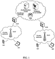
- the network based Identifier and Locator separation framework mainly includes: a radio access network (RAN), an access gateway router (AGR for short), a general switch router (GSR for short), a mapping server (identifier mapping server, IDMS for short), an authentication center, etc. Those are described separately as follows.
- the AGR is responsible for providing access service for various mobile nodes, allocating the RID for the accessed user, and transmitting the user data message in the backbone network after encapsulating the identifier into the data message.
- the AGR when receiving the data message transmitted by the terminal, queries the AID-RID mapping table in the local cache (CACHE) according to the destination address (that is the AID of the correspondent node) in the data message. Specifically, if the corresponding AID-RID mapping entry is queried out, then the AGR encapsulates the RID of the found communication terminal in the header of the message and transmits to the backbone network to perform the forwarding processing; if the corresponding AID-RID mapping entry is not queried out, the AGR forwards the data message to the backbone network, and initiates the process of querying the AID-RID mapping information (of the correspondent node) to the IDMS, and stores the corresponding AIDc-RIDc mapping returned by the IDMS locally to be ready for querying when forwarding the message subsequently.
- CACHE local cache
- the AGR when having not queried out the corresponding AID-RID mapping entry, can also select not to forward the data message to the backbone network but to initiate the process of querying the AID-RID mapping information (of the correspondent node) to the IDMS, and encapsulates the found RID of the correspondent node in the header of the message and transmits to the backbone network to perform the forwarding processing after the IDMS returns the corresponding AIDc-RIDc mapping.
- the AGR when receiving the data message transmitted to the terminal, performs the de-encapsulation processing to the data message, strips the newly added header of the message including the RID in the data message, and transmits to the terminal.
- the main functions of the GSR are to perform the route selection and forward the data message according to the routing location identifier (RID) in the data message.
- RID routing location identifier
- the IDMS is mainly responsible for maintaining the mapping relationship of the access identifier and location identifier in the network, and providing the querying service to the access gateway router and other mapping servers.
- the authentication center is responsible for recording the information such as the user type, user service grade, etc., and performing validity authentication and authorization to the user when the user accesses.
- the authentication center supports the two-way authentication between the network and the user.
- the radio access network is responsible for providing and maintaining the two-layer link from the user terminal to the AGR; and responsible for wireless resource management in the case of the cell mobile network application scene.
- the network can be divided into an access network and a backbone network.
- the access network locates at the edge of backbone network, responsible for the accessing of all terminals, and in the RAN section, all the user terminals use AID to address.
- the backbone network is responsible for the routing of the terminals accessing through different access networks.
- the access network and the backbone network do not overlap on the topological relationship.
- AID is used in the application layer between the communication hosts to identify the opposite end, and the communication between the user terminals can perform with the only need of using the AID of the opposite end.
- the access gateway router locates at the boundary point of the backbone network and the access network, interfacing with the access network and the backbone network, responsible for providing the access service for the terminal, maintaining the user connection, forwarding the user data, etc. All the communications between user terminals are forwarded and managed through the access gateway router in the located access network. The data message between the terminals in the service range of the same access gateway router is forwarded to the opposite end directly.
- the data message between the terminals locating at service ranges of different access gateway routers is forwarded as follows: when the terminal sends out the data message, the corresponding access gateway router carries the RID information (that RID is corresponding to the AID) in the forwarded data message; correspondingly, when the terminal receives the data message, the access gateway router performs the opposite operation, that is, strips the RID information and forwards the data message to the terminal.
- the mapping server stores the mapping relationship between Identifier and Locator allocated to all accessed user terminals in the network, and analyzes the identifier relationship through the signaling interacting with the access gateway router.
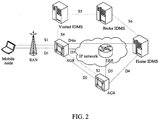
- the related interfaces of the network framework of the above network based Identifier and Locator separation framework are shown in FIG. 2 .
- the S1/D1 is the interface between the user terminal and the AGR
- S1 is used for the signaling of the user access management
- the D1 is the data forwarding interface.
- S2 is used for the handover management signaling during the handover between the AGRs
- the D2 is for data forwarding during the handover between the AGRs.
- D3 is a data forwarding interface between the AGR and the GSR
- the S4/S5/S6 are the signaling interfaces used for inquiring and maintaining the AID-RID mapping relationship.
- D4m is a data forwarding interface between the AGR and IDMS. when there is no direct coupling relationship between a visited IDMS and a home IDMS, the Broke IDMS forwards the signaling between the visited IDMS and the home IDMS.
- the method of handover management realizing mobility support in the above-mentioned network framework is described hereinafter.
- the CN and the MN establish communication, receive and transmit the data message with each other.
- the AGR where the CN is located can query the mapping relationship between the AID and the RID of the MN from the mapping server IDMS according to the AID carried in the message of the MN, thus obtaining the route location identifier RID of the MN.
- the handover flow is triggered.
- the handover-out gateway AGR and the handover-in gateway AGR establish the forwarding relationship, and in the handover process or after the handover finishes, the handover-out gateway AGR forwards the received data message transmitted towards the MN to the handover-in gateway AGR, and the handover-in gateway AGR forwards to the MN.
- the AID-RID mapping relationship of the MN stored in the mapping server IDMS is updated, and the CN is notified of the new AID-RID mapping relationship, and other associated constituent parts are notified in the network.
- the specific flow is as shown in FIG. 3 and includes the following steps.
- the source RAN when determining that the MN needs to perform the handover, transmits a handover request carrying the identifier information, such as AIDm and so on, of the target RAN and the MN to the handover-out gateway AGR1.
- the source RAN can perform the handover judgment combining with the distribution situation of the radio resource according to the information, such as strong or weak wireless signal of the MN, system load, etc.
- the source RAN is the radio access network that the MN accesses currently, and the handover-out gateway is the access gateway router that the MN connects currently.
- the AGR1 After receiving the handover request message transmitted by the radio access system, finds the handover-in AGR2 according to the identifier information of the target RAN and forwards the handover request message to the AGR2, and the message carries the identifier information of the MN.
- the corresponding relationship table of the adjacent RAN and AGR is configured in the AGR with the adjacent relationship in physical locations, and therefore, the AGR1 will store the corresponding relation table entry of the RAN and the AGR2.
- step 103 the AGR2, after receiving the handover request message, allocates a new RID for that user, establishes the AIDm-RIDm mapping relationship of that mobile node in the AGR2, and interacts messages with the target RAN to allocate the radio resource for the MN.
- step 104 the AGR2 transmits a handover response message to the AGR1, interacts the messages with the AGR1 to obtain the mapping relationship AIDc-RIDc of all CNs in data communication with the MN, and establishes the data forwarding relationship with the AGR1.
- the operation of establishing the data forwarding relationship here is the content of the related art, of which the typical practice is realized by way of tunnel encapsulation, that is, the AGR1, when receiving the data message transmitted by the MN from the AGR2, strips the tunnel encapsulation of the AGR1-AGR2, and then transmits to the CN; the AGR1, when receiving the data message transmitted towards the MN from the CN, adds the tunnel encapsulation of the AGR1-AGR2 in the header of the message and then transmits to the AGR2, and the AGR2 de-encapsulates and transmits to the MN.
- the AGR1 after recording the forwarding relationship with the AGR2, forwards the data message transmitted towards the MN, received during the handover, to the MN through the AGR2; in another example, the AGR1 can also cache the data message transmitted towards the MN first, and after the handover finishes, for example after receiving the handover completion message of the AGR2, then the AGR1 forwards the cached data message to the MN through the AGR2.
- the AGR1 after receiving the handover response, forwards the data directly to the AGR2 or forwards the data after caching.
- step 105 the AGR2 initiates a mapping update flow to the IDMS to update the AIDm-RIDm mapping relationship of that user terminal stored by the IDMS.
- step 104 can be performed with step 104 at the same time, and the precedence order of the two is not limited here.
- step 106 after receiving the handover response message transmitted by the AGR2, the AGR1 transmits the handover command to the MN through the source RAN.
- step 107 after receiving the handover command, the MN initiates the access request to the target RAN, requests to establish the communication link with the AGR2, and receives and transmits and receives the data message from the communication link.
- step after the MN receives the handover command, the communication contact with the source RAN/AGR1 is interrupted, and the MN needs to access the network from the target RAN side.
- step 108 AGR2, after receiving the handover completion message transmitted by the target RAN, forwards to the AGR1.
- step 109 the AGR2, according to the mapping relationship AIDc-RIDc of all CNs in the data communication with the MN obtained from the AGR1, initiates the mapping update relationship request to the access gateway router AGR3 directed by the RIDc, and notifies the access gateway router AGR3 of the CN to update the stored AIDm-RIDm mapping relationship of the MN.
- the AGR1 will delete the forwarding relationship between the AGR1 and the AGR2 of the MN, for example, during the handover, the AGR1 can set a message timer for forwarding the data to the AGR2, and the AGR1 will delete the forwarding relationship with the AGR2 after the timer is overtime; and/or the AGR2 transmits a signal for deleting the forwarding relationship to the AGR1 after finishing the process of updating the mapping relationship of the AGR3 of all CNs in communicating with the MN (the embodiment takes the case that the MN only has one correspondent node as an example for description), and the AGR1 deletes the forwarding relationship between the AGR1 and the AGR2 of the MN after receiving that signal.
- the handover management of the mobile node in the movement process mainly involves the interaction and processing among the mobile node, the access gateway router and the mapping server to guarantee that the communication between the user terminals which are initiating a communication or communicating in the handover process is performed normally, and meanwhile try to reduce the packet loss rate in the handover process.
- the access switch router AGRm needs to store the information of all CNs for each locally accessed MN, and notifies the new Identifier and Locator mapping relationship of the MN to the access switch router AGRc to which the CN belongs according to the stored information.
- the access switch router is required to have the following functions.
- mapping route table entry can be performed in the following ways.
- the access switch router AGRm decides which entry is to be replaced, and replaces it with a new mapping route entry. For example, the mapping route entry not being queried in the maximum duration is replaced, the entry with a minimum number of the querying times is replaced, or the entry with a lower preferential rank is replaced, etc.
- the network framework which the present example is based on can be a locator/ID separation protocol (LISP) + alternative logical topology (ALT), wherein, the egress tunnel router (ETR) / ingress tunnel router (ITR) are corresponding to the AGR (that is, the AGR is equal to the function combination of the ETR and ITR) in example one and the mapping distribution node (map-resolver) / mapping server (map-server) are responding to the IDMS in example 1.
- the endpoint identifiers (EID) in the LISP are corresponding to the AID in example 1
- the route address (routing locators, RLOC) is corresponding to the RID in example 1.
- the specific implementation steps are totally the same as the example 1.
- the tunnel routers are introduced in the LISP system, and the terminal encapsulates the LISP when transmitting the data packet and the data packet is de-encapsulated before arriving to the destination.
- the ITR encapsulates a new LISP header for each packet and the new header is stripped in the ETR. That operation process is corresponding to that in example one, the AGR transmits the data message of the terminal in backbone network after encapsulating Identifier in the data message, and when receiving the data message transmitted towards the terminal, the AGR de-encapsulates and then transmits to the terminal after receiving the data message transmitted to the terminal.
- the IP addresses of "the external layer header" in the LISP data packet are RLOCs.
- the ITR performs the EID-to-RLOC searching to determine the route path to the ETR, and the ETR takes the RLOC as its one address. That operation is corresponding to that in Example one, the AGR encapsulates the RID route information in the data message transmitted by the terminal, and then the data message is routing forwarded to the AGR where the correspondent node directed by the destination RID is located through the GSR.
- the ALT as one topological structure in the Internet, is identified as a plane with special functions by the way defined by the LISP system, which is equal to the IDMS in the backbone network in Example one.
- the network framework which the present example is based on can be an integration network, as shown in FIG. 5 , wherein, the access router is corresponding to the AGR in Example one.
- the specific implementation steps of the present example are the same as the Example one, which will not go into details here.
- the present invention further provides a system for handover management of a mobile node, applied to an Identifier and Locator separation framework including a MN, a RAN and an AGR, wherein, the AGR further includes a route location identifier allocating module, a correspondent node information obtaining module and a mapping relationship updating module, wherein:
- the AGR further comprises a route location identifier allocating module, a correspondent node information obtaining module and a mapping relationship updating module, wherein, the route location identifier allocating module is configured to, after receiving the handover request of the MN, allocate a new route location identifier (RID) for the MN and transmit to the mapping relationship updating module; the correspondent node information obtaining module is configured to, after receiving the handover request, obtain information of all CNs in communication with the MN from the AGR of the source RAN of the MN and transmit to the mapping relationship updating module; after receiving the request for obtaining information of the correspondent node transmitted by the AGR of the target RAN which the MN hands over to, transmit the information of all CNs in communication with the MN to the AGR of the target RAN; the mapping relationship updating module is configured to, after receiving the new RID of the MN, establish a new Identifier and Locator mapping relationship of the MN, and notify the AGR where the CN is located the new Identifier and Locator mapping
- mapping relationship updating module of the AGR2 is further configured to, after establishing the new Identifier and Locator mapping relationship of the MN, initiate a mapping update request to a mapping server to request to update the Identifier and Locator mapping relationship of the MN.
- the AGR further comprises a data forwarding module, wherein, the data forwarding module of the AGR of the target RAN is configured to, after receiving the handover request, establish a forwarding relationship with the AGR of the source RAN, and transmit a data message transmitted towards the MN to the MN after receiving the handover completion message; the data forwarding module of the AGR of the source RAN is configured to, according to the established forwarding relationship, transmit the received data message transmitted towards the MN to the AGR of the target RAN during the handover or after receiving the handover completion message.
- mapping relationship updating module of the AGR of the target RAN is further configured to, after notifying the new Identifier and Locator mapping relationship of the MN to the AGR where the CN is located, transmit a deleting instruction to the AGR of the source RAN; the mapping relationship updating module of the AGR of the source RAN is further configured to, delete the forwarding relationship according to the deleting instruction, and/or, delete the forwarding relationship in a certain time after establishing the forwarding relationship.
- the AGR further comprises a timing module and an entry managing module, wherein, the timing module is configured to set a time cycle of the polling timer, and notify the entry managing module when the time cycle of the polling timer arrives; the entry managing module is configured to store the Identifier and Locator mapping route table of all CNs in communication with the MN, set a timer label for each entry when establishing the entries of the mapping route table, and an initialization value of the timer label is a set default integer value; when querying a certain entry of the mapping route table every time, reset the timer label corresponding to the entry of the mapping route table to the initialization value; and when receiving the notification of the timing module, poll the entries of the mapping route table, reduce the timer label corresponding to each entry of the mapping route table by 1, and then delete a certain entry of the mapping route table when detecting that the timer label of the entry of the mapping route table is 0.
- the example of the present invention also provides an AGR implementing user data management in a handover process of a
- mapping relationship updating module is further configured to, after establishing the new Identifier and Locator mapping relationship of the MN, initiate a mapping update request to a mapping server to request to update the Identifier and Locator mapping relationship of the MN.
- the AGR further comprises a data forwarding module, wherein, the data forwarding module of the AGR2 is configured to, after receiving the handover request, establish a forwarding relationship with the AGR1, and transmit a data message transmitted towards the MN to the MN after receiving the handover completion message; the data forwarding module of the AGR1 is configured to, according to the established forwarding relationship, transmit the received data message transmitted towards the MN to the AGR2 during the handover or after receiving the handover completion message.
- mapping relationship updating module of the AGR of the target RAN is further configured to, after notifying the AGR where the CN is located of the new Identifier and Locator mapping relationship of the MN, transmit a deleting instruction to the AGR of the source RAN; the mapping relationship updating module of the AGR of the source RAN is further configured to, delete the forwarding relationship according to the deleting instruction, and/or, delete the forwarding relationship in a certain time after establishing the forwarding relationship.
- the AGR further comprises a timing module and an entry managing module, wherein, the timing module is configured to set a time cycle of a polling timer, and notify the entry managing module when the time cycle of the polling timer arrives; the entry managing module is configured to store the Identifier and Locator mapping route table of all CNs in communication with the MN, set a timer label for each entry when establishing the entries of the mapping route table, wherein, an initialization value of the timer label is a set default integer value; when querying a certain entry of the mapping route table every time, reset the timer label corresponding to the entry of the mapping route table to the initialization value; and when receiving the notification of the timing module, poll the entries of the mapping route table, reduce the timer label corresponding to each entry of the mapping route table by 1, and delete a certain entry of the mapping route table when detecting that the timer label of the entry of the mapping route table is 0.
- the timing module is configured to set a time cycle of a polling timer, and notify the entry managing module when
- the scheme in the present invention realizes the handover management of the mobility in the Identifier and Locator separation framework based on the network, provides a simple handover management procedure by combining the characteristic of the mobile communication network, provides an optimized user data management method in the handover management procedure, and makes the function distribution and the main procedure of each function entity in the handover management procedure clearly.
- a method for compatible transition is provided for the current mobile communication cell network, and the related procedure of mobility management in the network based Identifier and Locator separation framework is implemented by network side equipments, and there is no new function requirement for the mobile node and the mobile node can support without changing.
Landscapes
- Engineering & Computer Science (AREA)
- Computer Networks & Wireless Communication (AREA)
- Signal Processing (AREA)
- Mobile Radio Communication Systems (AREA)
Claims (17)
- Procédé pour la gestion de transfert d'un noeud mobile, MN, pour un framework de séparation d'identifiant et de localisateur, lorsqu'un réseau d'accès radio, RAN, source actuel du MN détermine que le MN doit initier un transfert, ce procédé comprenant :
l'initiation (101), par le RAN source, d'une requête de transfert comprenant des informations d'un RAN cible pour un premier routeur de passerelle d'accès AGR1 et la transmission (102), par l'AGR1, de la requête de transfert à un deuxième routeur de passerelle d'accès, AGR2, du RAN cible selon les informations du RAN cible :l'allocation (103), par l'AGR2, après la réception de la requête de transfert, d'un nouvel identifiant d'itinéraire, RID, pour le MN, l'établissement (103) d'une nouvelle relation de mappage d'identifiant et de localisateur du MN qui mappe une relation entre un AID du MN et le nouveau RID du MN ;le retour (104), par l'AGR2, d'une réponse de transfert à l'AGR1, l'obtention (104) d'une relation de mappage entre l'AID et le RID de tous les noeuds correspondants, CN, en communication avec le MN, en provenance de l'AGR1 ;après la réception de la réponse de transfert, la transmission (106), par l'AGR1, d'une commande de transfert au MN par l'intermédiaire du RAN source ;l'initiation (107), par le MN, d'une requête d'accès au RAN cible par l'intermédiaire de l'AGR2 selon la commande transfert reçue et finition du transfert au RAN cible ; après la réception d'un message de réalisation de transfert transmis par le RAN cible, la notification (109), par l'AGR2, d'un troisième routeur de passerelle d'accès, AGR3, où se trouve le CN, de la nouvelle relation de mappage d'identifiant et de localisateur du MN selon les informations obtenues du CN ;l'AID étant configuré pour chaque utilisateur et restant inchangé tout le temps dans un processus de mouvement ;ce procédé comprenant en outre :l'établissement (104), par l'AGR2, après la réception de la requête de transfert, d'une relation de réacheminement avec l'AGR1 ; etla transmission par l'AGR1 d'un message de données reçu transmis en direction du MN vers l'AGR2 pendant le transfert et le réacheminement, par l'AGR2, du message de données vers le MN. - Procédé selon la revendication 1, comprenant en outre :
l'initiation (105), par l'AGR2, après l'établissement de la nouvelle relation de mappage entre l'identifiant et le localisateur du MN, d'une requête de mise à jour de mappage à un serveur de mappage afin de demander une mise à jour d'une relation de mappage entre l'AID et le RID du MN. - Procédé selon la revendication 1, dans lequel
dans l'étape de l'établissement (104), par l'AGR2, de la relation de réacheminement avec l'AGR1, l'AGR2 et l'AGR1 établissent la relation de réacheminement au moyen d'une encapsulation de tunnel pour réacheminer le message de données. - Procédé selon la revendication 1, comprenant en outre :
la suppression par l'AGR1, de la relation de réacheminement dans un temps déterminé après l'établissement de la relation de réacheminement et/ou la transmission, par l'AGR2, après la notification à l'AGR où se trouve du CN de la nouvelle relation de mappage entre l'identifiant et le localisateur du MN, d'une instruction de suppression à l'AGR1 et la suppression, par l'AGR1, de la relation de réacheminement selon l'instruction de suppression. - Procédé selon la revendication 1, dans lequel
l'AGR1 stocke une table d'itinéraire de mappage d'identifiant et de localisateur de tous les CN en communication avec le MN et effectue un processus de maturation sur la table d'itinéraire de mappage de la manière suivante :réglage d'un timer de sondage ;lors de l'établissement d'entrées de la table d'itinéraires de mappage, le réglage d'une étiquette de timer pour chaque entrée, et une valeur d'initialisation de l'étiquette de timer étant une valeur entière réglée par défaut ;lors de la recherche d'une entrée déterminée de la table d'itinéraires de mappage, la réinitialisation à chaque fois de l'étiquette de timer correspondant à l'entrée de la table d'itinéraires de mappage à la valeur d'initialisation ;lorsqu'un cycle du timer de sondage arrive à terme, sondage de la table d'itinéraires de mappage, réduction de l'étiquette de timer correspondant à chaque entrée de la table d'itinéraires de mappage dans la table d'itinéraires de mappage de 1 et suppression d'une entrée déterminée de la table d'itinéraires de mappage lorsqu'il est détecté que l'étiquette de timer de l'entrée de la table d'itinéraires de mappage est égale à 0. - Système de gestion de transfert d'un noeud mobile, MN, pour un framework de séparation d'identifiant et de localisateur, ce système comprenant un noeud mobile, MN, un réseau d'accès radio ressource RAN, un RAN cible, un premier routeur de passerelle d'accès, AGR1 et un deuxième routeur de passerelle d'accès, AGR2,
un RAN source actuel du MN étant conçu pour initier, lors de la détermination que le MN doit initier un transfert, une requête de transfert comprenant des informations d'un RAN cible à l'AGR1 ;
l'AGR1 étant conçu pour transmettre la requête de transfert à l'AGR2 du RAN cible selon les informations du RAN cible dans la requête de transfert reçue ; après la réception d'une réponse de transfert en provenance de l'AGR2, pour transmettre une commande de transfert au MN par l'intermédiaire du RAN source ;
l'AGR2 étant conçu pour retourner, après la réception de la requête de transfert en provenance de l'AGR1, la réponse de transfert; l'AGR2 comprenant un module d'allocation d'identifiant de localisation d'itinéraire, un module d'obtention d'informations de noeud correspondant, un module de mise à jour de relation de mappage et un module de réacheminement de données,
le module d'allocation d'identifiant de localisation d'itinéraire étant conçu pour allouer, après la réception de la requête de transfert du MN, un nouvel identifiant de localisation d'itinéraire, RID, pour le MN et pour transmettre le nouveau RID au module de mise à jour de relation de mappage ;
le module d'obtention d'informations de noeud correspondant étant conçu pour obtenir, après la réception de la requête de transfert, des informations de tous les noeuds correspondants, CN, en communication avec le MN, en provenance de l'AGR du RAN source du MN et pour les transmettre au module de mise à jour de la relation de mappage ;
le module de mise à jour de relation de mappage étant conçu pour établir, après la réception du nouveau RID du MN, une nouvelle relation de mappage d'identifiant et de localisateur du MN qui est une relation de mappage entre un AID du MN et le nouveau RID du MN, et pour notifier à un troisième routeur de passerelle d'accès, AGR3, où se trouve un noeud correspondant, CN, la nouvelle relation de mappage d'identifiant et de localisateur du MN selon les informations du CN ;
le module de réacheminement de données de l'AGR2 du RAN cible étant conçu pour établir, après la réception de la requête de transfert, une relation de réacheminement avec l'AGR1 du RAN source ;
l'AGR1 comprenant également un module de réacheminement de données, le module de réacheminement de connées de l'AGR1 du RAN source étant conçu pour transmettre, selon une relation de réacheminement établie avec l'AGR2, le message de données reçu transmis en direction du MN vers l'AGR2 du RAN cible pendant le transfert ;
le MN étant conçu pour initier, selon la commande de transfert reçue, la requête d'accès au RAN cible par l'intermédiaire de l'AGR2 et pour terminer le transfert vers le RAN cible ;
l'AID étant configuré pour chaque utilisateur et restant inchangé tout le temps dans un processus de mouvement. - Système selon la revendication 6, dans lequel le RAN cible est conçu pour terminer l'accès du MN selon la requête d'accès reçue et pour transmettre un message de fin de transfert à l'AGR2.
- Système selon la revendication 7, dans lequel
l'AGR1 comprend un module d'obtention d'informations de noeud correspondant,
le module d'obtention d'informations de noeud correspondant étant conçue pour transmettre, après la réception de la requête pour l'obtention d'informations du noeud correspondant transmise par l'AGR2 du RAN cible vers lequel le MN effectue le transfert, d'une relation de mappage entre l'AID et le RID de tous les CN en communication avec le MN à l'AGR2 du RAN cible. - Système selon la revendication 8, dans lequel
le module de mise à jour de relation de mappage de l'AGR2 est en coutre conçu pour initier, après l'établissement de la nouvelle relation de mappage d'identifiant et de localisateur du MN, une requête de mise à jour de mappage à un serveur de mappage afind e demander une mise à jour d'une relation de mappage entre l'AID et le RID du MN. - Système selon la revendication 8, dans lequel
l'AGR1 et l'AGR2 comprennent en outre un module de réacheminement de données,
le module de réacheminement de données de l'AGR2 du RAN cible étant également conçu pour transmettre un message de données transmis en direction du MN vers le MN après le message de fin de transfert en provenance du RAN cible. - Système selon la revendication 10, dans lequel
le module de mise à jour de relation de mappage de l'AGR2 du RAN cible est en outre conçu pour transmettre, après la notification de la nouvelle relation de mappage d'identifiant et de localisateur du MN à l'AGR3 où se trouve le CN, une instruction de suppression à l'AGR1 du RAN source ;
l'AGR1 comprend également un module de mise à jour de relation de mappage, le module de mise à jour de relation de mappage de l'AGR1 du RAN source étant conçu pour supprimer la relation de réacheminement selon l'instruction de suppression et/ou supprimer la relation de réacheminement dans un temps déterminé après l'établissement de la relation de réacheminement. - Système selon l'une des revendications 7 à 11, dans lequel
l'AGR1 comprend en outre un module de minutage et un module de gestion d'entrée,
le module de minutage étant conçu pour régler un cycle temporal du timer de sondage et notifier au module de gestion d'entrée quand le cycle temporel du timer de sondage arrive à terme ;
le module de gestion d'entrée étant conçu pour stocker la table d'itinéraires de mappage d'identifiant et de localisateur de tous els CN en communication avec le MN, régler une étiquette de timer pour chaque entrée lors de l'établissement des entrées de la table d'itinéraires de mappage et une valeur d'initialisation de l'étiquette de timer étant une valeur entière réglée par défaut ; lors de la recherche d'une entrée déterminée de la table d'itinéraires de mappage, pour réinitialiser, à chaque fois, de l'étiquette de timer correspondant à l'entrée de la table d'itinéraires de mappage à la valeur d'initialisation ; et, lors de la réception de la notification du module de minutage, pour sonder les entrées de la table d'itinéraires de mappage, réduire l'étiquette de timer correspondant à chaque entrée de la table d'itinéraires de mappage de 1 puis supprimer une entrée déterminée de la table d'itinéraires de mappage lorsqu'il est détecté que l'étiquette de timer de l'entrée de la table d'itinéraires de mappage est égale à 0. - Routeur de passerelle d'accès AGR de gestion de données d'utilisateurs dans un processus de transfert d'un noeud mobile, MN pour un framework de séparation d'identifiant et de localisateur, comprenant :l'AGR est conçu pour recevoir une requête de transfert comprenant des informations d'un RAN cible en provenance d'un RAN source et pour transmettre la requête de transfert à un deuxième routeur de passerelle d'accès, AGR2 du RAN cible selon les informations du RAN cible ;l'AGR comprend un module d'allocation d'identifiant de localisation d'itinéraire, un module d'obtention d'informations de noeud correspondant, un module de mise à jour de relation de mappage et un module de réacheminement de données,le module d'allocation d'identifiant de localisation d'itinéraire étant conçu pour allouer, après la réception de la requête de transfert en provenance d'un premier routeur de passerelle d'accès, AGR1, du réseau d'accès radio, RAN, source du MN, un nouvel identifiant de localisation d'itinéraire, RID, au MN et pour transmettre le nouveau RID au module de mise à jour de relation de mappage ;le module d'obtention d'informations de noeud correspondant étant pour obtenir, après la réception de la requête de transfert, les informations de tous les noeuds correspondants, CN, en communication avec le MN en provenance de l'AGR1 et pour transmettre les informations de tous les CN en communication avec le MN au module de mise à jour de relation de mappage ; pour transmettre, après la réception de la requête pour l'obtention d'informations du noeud correspondant transmise par l'AGR2 d'un RAN cible vers lequel le MN effectue le transfert, une relation de mappage entre l'AID et le RID de tous les CN en communication avec le MN à l'AGR2 du RAN cible ;le module de mise à jour de relation de mappage étant conçu pour établir, après la réception du nouveau RID du MN, une nouvelle relation de mappage d'identifiant et de localisateur du MN qui est une relation de mappage entre un AID du MN et le nouveau RID du MN, et pour notifier à un troisième routeur de passerelle d'accès, AGR3, où se trouve le CN, la nouvelle relation de mappage d'identifiant et de localisateur du MN selon les informations du CN ;le module de réacheminement de données étant conçu pour établir, après la réception de la requête de transfert, une relation de réacheminement avec l'AGR1 ; pour transmettre, selon une relation de réacheminement établie avec l'AGR2, le message de données reçu, en direction du MN vers l'AGR2 du RAN du MN pendant le transfert ;l'AGR étant également conçu pour retourner, après la réception de la requête de transfert en provenance de l'AGR1, la réponse de transfert ; pour transmettre, après la réception d'une réponse de transfert en provenance de l'AGR2, une commande de transfert au MN par l'intermédiaire du RAN source ;l'AID étant configuré pour chaque utilisateur et restant inchangé tout le temps dans un processus de mouvement.
- AGR selon la revendication 13, dans lequel
le module de mise à jour de relation de mappage est en outre conçu pour initier, après l'établissement de la nouvelle relation de mappage d'identifiant et de localisateur du MN, une requête de mise à jour de mappage à un serveur de mappage, afin de demander la mise à jour d'une relation de mappage entre l'AID et le RID du MN. - AGR selon la revendication 13, dans lequel
le module de réacheminement des données est conçu pour transmettre un message de données en direction du MN au MN après la réception d'un message de fin de transfert en provenance du RAN cible. - AGR selon la revendication 13, 14 ou 15 dans lequel
le module de mise à jour de relation de mappage est en outre conçu pour transmettre, après la notification à l'AGR3, où se trouve le CN, de la nouvelle relation de mappage d'identifiant et de localisateur du MN, une instruction de suppression à l'AGR1 du RAN source ;
module de mise à jour de relation de mappage est en outre conçu pour supprimer la relation de réacheminement selon l'instruction de suppression et/ou pour supprimer la relation de réacheminement dans un temps déterminé après l'établissement de la relation de réacheminement. - AGR selon la revendication 16, dans lequel
l'AGR comprend en outre un module de minutage et un module de gestion d'entrée,
le module de minutage étant conçu pour régler un cycle temporel d'un timer de sondage et notifier au module de gestion d'entrée quand le cycle temporel arrive à son terme ;
le module de gestion d'entrée est conçu pour stocker la table d'itinéraires de mappage d'identifiant et de localisateur de tous les CN en communication avec le MN, régler une étiquette de timer pour chaque entrée lors de l'établissement des entrées de la table d'itinéraires de mappage, une valeur d'initialisation de l'étiquette de timer étant une valeur entière réglée par défaut ; pour réinitialiser, lors de la recherche d'une entrée déterminée de la table d'itinéraires de mappage, à chaque fois, l'étiquette de timer correspondant à l'entrée de la table d'itinéraires de mappage à la valeur d'initialisation ; et, lors de la réception de la notification du module de minutage, sonder les entrées de la table d'itinéraires de mappage , réduire l'étiquette de timer correspondant à chaque entrée de la table d'itinéraires de mappage de 1 et supprimer une entrée déterminée de la table d'itinéraires de mappage lorsqu'il est détecté que l'étiquette de timer de l'entrée de la table d'itinéraires de mappage est égale à 0.
Applications Claiming Priority (2)
| Application Number | Priority Date | Filing Date | Title |
|---|---|---|---|
| CN2009101746916A CN102026318B (zh) | 2009-09-17 | 2009-09-17 | 切换管理及切换时用户数据管理的方法、系统和agr |
| PCT/CN2010/076313 WO2011032455A1 (fr) | 2009-09-17 | 2010-08-24 | Procédé, système et routeur de passerelle d'accès pour gestion de transfert et gestion de données d'utilisateur lors d'un transfert |
Publications (3)
| Publication Number | Publication Date |
|---|---|
| EP2466954A1 EP2466954A1 (fr) | 2012-06-20 |
| EP2466954A4 EP2466954A4 (fr) | 2016-10-26 |
| EP2466954B1 true EP2466954B1 (fr) | 2019-10-09 |
Family
ID=43758089
Family Applications (1)
| Application Number | Title | Priority Date | Filing Date |
|---|---|---|---|
| EP10816659.6A Active EP2466954B1 (fr) | 2009-09-17 | 2010-08-24 | Procédé, système et routeur de passerelle d'accès pour gestion de transfert et gestion de données d'utilisateur lors d'un transfert |
Country Status (3)
| Country | Link |
|---|---|
| EP (1) | EP2466954B1 (fr) |
| CN (1) | CN102026318B (fr) |
| WO (1) | WO2011032455A1 (fr) |
Families Citing this family (9)
| Publication number | Priority date | Publication date | Assignee | Title |
|---|---|---|---|---|
| CN102232284B (zh) * | 2011-05-06 | 2014-02-19 | 华为技术有限公司 | 提高转发表访问性能的方法和装置 |
| CN102868599B (zh) * | 2011-07-08 | 2017-06-30 | 南京中兴新软件有限责任公司 | 身份与位置分离协议移动节点及移动控制方法、移动节点 |
| CN103036758B (zh) * | 2011-10-10 | 2017-02-15 | 中兴通讯股份有限公司 | 一种标识网与传统网络互联互通的方法、asr及isr |
| CN103095857A (zh) * | 2011-10-28 | 2013-05-08 | 中兴通讯股份有限公司 | 一种接入、退出网络、发送报文的方法及网络侧设备 |
| CN103108375A (zh) | 2011-11-14 | 2013-05-15 | 中兴通讯股份有限公司 | 一种切换过程中路由优化的方法及系统及接入网元 |
| CN103167464B (zh) * | 2011-12-09 | 2018-06-15 | 中兴通讯股份有限公司 | 触发更新移动节点映射信息的方法、ms和mn |
| RU2669582C2 (ru) | 2014-05-30 | 2018-10-12 | Хуавэй Текнолоджиз Ко., Лтд. | Способ и устройство смены пути услуги |
| CN104506971A (zh) * | 2014-12-31 | 2015-04-08 | 绵阳芯联芯网络科技有限公司 | 基于分离映射机制的无源光网络移动漫游的实现方法 |
| CN119789069B (zh) * | 2024-12-31 | 2025-11-18 | 中国电信股份有限公司技术创新中心 | 全息通信移动管理方法及相关设备 |
Family Cites Families (9)
| Publication number | Priority date | Publication date | Assignee | Title |
|---|---|---|---|---|
| KR100568152B1 (ko) * | 2003-10-20 | 2006-04-07 | 삼성전자주식회사 | 이동망 환경에서의 크로스오버 라우터 탐색방법,자원예약방법 및 이를 이용하는 자원 예약 시스템 |
| CN100428843C (zh) * | 2004-12-02 | 2008-10-22 | 华为技术有限公司 | 宽带移动接入网系统及其方法 |
| CN101330527B (zh) * | 2007-06-22 | 2011-02-09 | 华为技术有限公司 | 移动节点、接入路由器及快速切换的地址配置方法 |
| CN101383755B (zh) * | 2007-09-04 | 2012-10-17 | 华为技术有限公司 | 代理移动IPv6切换方法及相关网络实体 |
| CN100521660C (zh) * | 2007-09-13 | 2009-07-29 | 北京交通大学 | 一种一体化网络移动切换管理的实现方法 |
| FI20085194A0 (fi) * | 2008-02-29 | 2008-02-29 | Nokia Siemens Networks Oy | Menetelmä ja laite kanavanvaihtoproseduuria varten jatkolähetyslaajennuksen sisältävässä tietoliikenneverkossa |
| CN102045693B (zh) * | 2009-10-16 | 2015-05-20 | 中兴通讯股份有限公司 | 信息上报/通知、切换和数据转发方法、an及ilr |
| CN101951589B (zh) * | 2009-10-17 | 2015-07-22 | 中兴通讯股份有限公司 | 信息获取/通知、数据报文转发和切换的方法及接入节点 |
| CN102056258B (zh) * | 2009-10-30 | 2015-08-12 | 中兴通讯股份有限公司 | 一种实现终端切换的方法及系统 |
-
2009
- 2009-09-17 CN CN2009101746916A patent/CN102026318B/zh active Active
-
2010
- 2010-08-24 EP EP10816659.6A patent/EP2466954B1/fr active Active
- 2010-08-24 WO PCT/CN2010/076313 patent/WO2011032455A1/fr not_active Ceased
Non-Patent Citations (1)
| Title |
|---|
| None * |
Also Published As
| Publication number | Publication date |
|---|---|
| WO2011032455A1 (fr) | 2011-03-24 |
| EP2466954A1 (fr) | 2012-06-20 |
| CN102026318B (zh) | 2013-09-11 |
| EP2466954A4 (fr) | 2016-10-26 |
| CN102026318A (zh) | 2011-04-20 |
Similar Documents
| Publication | Publication Date | Title |
|---|---|---|
| EP2466954B1 (fr) | Procédé, système et routeur de passerelle d'accès pour gestion de transfert et gestion de données d'utilisateur lors d'un transfert | |
| CN102045693B (zh) | 信息上报/通知、切换和数据转发方法、an及ilr | |
| US9622072B2 (en) | Communication method, method for forwarding data message during the communication process and communication node thereof | |
| US8711749B2 (en) | Information obtaining and notification, data message forwarding and handover method and access node | |
| US8804746B2 (en) | Network based on identity identifier and location separation architecture backbone network, and network element thereof | |
| CN106790732B (zh) | 地址转换方法、装置及系统、网络标识控制方法及装置 | |
| CN101621449B (zh) | mesh网络中终端接入和代理更新的方法、装置 | |
| WO2015021591A1 (fr) | Procédé et dispositif de stockage pour un contenu internet | |
| EP2466815B1 (fr) | Procédé et système de déclenchement d'acheminement de message de communication, d'informations et de données et de configuration de routage | |
| CN102547908B (zh) | 表维护方法、系统和接入网关路由器 | |
| US11206590B2 (en) | Method for realizing wireless network convergence | |
| CN103188752B (zh) | 一种在新型路由体系下移动终端零丢包的网络切换方法 | |
| CN102137468B (zh) | 实现无固定锚点切换的Wimax系统及其切换方法 | |
| CN102546356B (zh) | 一种保证标识网中移动节点服务质量的方法及系统 | |
| CN102547845B (zh) | 一种标识网中移动节点切换时数据报文的管理方法及系统 | |
| WO2012083685A1 (fr) | Procédé et système d'amélioration de l'efficacité d'utilisation d'une table de mappage et de routage | |
| CN102170674B (zh) | 实现无固定锚点切换的Wimax系统及其切换方法 | |
| KR20130007254A (ko) | 이기종 네트워크에서의 애니캐스트 주소를 이용한 서버 접속 지원 방법 및 그 장치 |
Legal Events
| Date | Code | Title | Description |
|---|---|---|---|
| PUAI | Public reference made under article 153(3) epc to a published international application that has entered the european phase |
Free format text: ORIGINAL CODE: 0009012 |
|
| 17P | Request for examination filed |
Effective date: 20120316 |
|
| AK | Designated contracting states |
Kind code of ref document: A1 Designated state(s): AL AT BE BG CH CY CZ DE DK EE ES FI FR GB GR HR HU IE IS IT LI LT LU LV MC MK MT NL NO PL PT RO SE SI SK SM TR |
|
| DAX | Request for extension of the european patent (deleted) | ||
| RIC1 | Information provided on ipc code assigned before grant |
Ipc: H04W 40/36 20090101ALI20160915BHEP Ipc: H04W 36/14 20090101ALN20160915BHEP Ipc: H04W 36/12 20090101AFI20160915BHEP |
|
| RA4 | Supplementary search report drawn up and despatched (corrected) |
Effective date: 20160922 |
|
| STAA | Information on the status of an ep patent application or granted ep patent |
Free format text: STATUS: EXAMINATION IS IN PROGRESS |
|
| 17Q | First examination report despatched |
Effective date: 20180417 |
|
| GRAP | Despatch of communication of intention to grant a patent |
Free format text: ORIGINAL CODE: EPIDOSNIGR1 |
|
| STAA | Information on the status of an ep patent application or granted ep patent |
Free format text: STATUS: GRANT OF PATENT IS INTENDED |
|
| RIC1 | Information provided on ipc code assigned before grant |
Ipc: H04W 36/12 20090101AFI20190409BHEP Ipc: H04W 40/36 20090101ALI20190409BHEP Ipc: H04W 36/14 20090101ALN20190409BHEP |
|
| INTG | Intention to grant announced |
Effective date: 20190430 |
|
| GRAS | Grant fee paid |
Free format text: ORIGINAL CODE: EPIDOSNIGR3 |
|
| GRAA | (expected) grant |
Free format text: ORIGINAL CODE: 0009210 |
|
| STAA | Information on the status of an ep patent application or granted ep patent |
Free format text: STATUS: THE PATENT HAS BEEN GRANTED |
|
| AK | Designated contracting states |
Kind code of ref document: B1 Designated state(s): AL AT BE BG CH CY CZ DE DK EE ES FI FR GB GR HR HU IE IS IT LI LT LU LV MC MK MT NL NO PL PT RO SE SI SK SM TR |
|
| REG | Reference to a national code |
Ref country code: GB Ref legal event code: FG4D |
|
| REG | Reference to a national code |
Ref country code: CH Ref legal event code: EP |
|
| REG | Reference to a national code |
Ref country code: IE Ref legal event code: FG4D |
|
| REG | Reference to a national code |
Ref country code: DE Ref legal event code: R096 Ref document number: 602010061465 Country of ref document: DE |
|
| REG | Reference to a national code |
Ref country code: AT Ref legal event code: REF Ref document number: 1190282 Country of ref document: AT Kind code of ref document: T Effective date: 20191115 |
|
| REG | Reference to a national code |
Ref country code: NL Ref legal event code: MP Effective date: 20191009 |
|
| REG | Reference to a national code |
Ref country code: LT Ref legal event code: MG4D |
|
| REG | Reference to a national code |
Ref country code: AT Ref legal event code: MK05 Ref document number: 1190282 Country of ref document: AT Kind code of ref document: T Effective date: 20191009 |
|
| PG25 | Lapsed in a contracting state [announced via postgrant information from national office to epo] |
Ref country code: SE Free format text: LAPSE BECAUSE OF FAILURE TO SUBMIT A TRANSLATION OF THE DESCRIPTION OR TO PAY THE FEE WITHIN THE PRESCRIBED TIME-LIMIT Effective date: 20191009 Ref country code: LV Free format text: LAPSE BECAUSE OF FAILURE TO SUBMIT A TRANSLATION OF THE DESCRIPTION OR TO PAY THE FEE WITHIN THE PRESCRIBED TIME-LIMIT Effective date: 20191009 Ref country code: AT Free format text: LAPSE BECAUSE OF FAILURE TO SUBMIT A TRANSLATION OF THE DESCRIPTION OR TO PAY THE FEE WITHIN THE PRESCRIBED TIME-LIMIT Effective date: 20191009 Ref country code: NL Free format text: LAPSE BECAUSE OF FAILURE TO SUBMIT A TRANSLATION OF THE DESCRIPTION OR TO PAY THE FEE WITHIN THE PRESCRIBED TIME-LIMIT Effective date: 20191009 Ref country code: PL Free format text: LAPSE BECAUSE OF FAILURE TO SUBMIT A TRANSLATION OF THE DESCRIPTION OR TO PAY THE FEE WITHIN THE PRESCRIBED TIME-LIMIT Effective date: 20191009 Ref country code: NO Free format text: LAPSE BECAUSE OF FAILURE TO SUBMIT A TRANSLATION OF THE DESCRIPTION OR TO PAY THE FEE WITHIN THE PRESCRIBED TIME-LIMIT Effective date: 20200109 Ref country code: BG Free format text: LAPSE BECAUSE OF FAILURE TO SUBMIT A TRANSLATION OF THE DESCRIPTION OR TO PAY THE FEE WITHIN THE PRESCRIBED TIME-LIMIT Effective date: 20200109 Ref country code: FI Free format text: LAPSE BECAUSE OF FAILURE TO SUBMIT A TRANSLATION OF THE DESCRIPTION OR TO PAY THE FEE WITHIN THE PRESCRIBED TIME-LIMIT Effective date: 20191009 Ref country code: GR Free format text: LAPSE BECAUSE OF FAILURE TO SUBMIT A TRANSLATION OF THE DESCRIPTION OR TO PAY THE FEE WITHIN THE PRESCRIBED TIME-LIMIT Effective date: 20200110 Ref country code: ES Free format text: LAPSE BECAUSE OF FAILURE TO SUBMIT A TRANSLATION OF THE DESCRIPTION OR TO PAY THE FEE WITHIN THE PRESCRIBED TIME-LIMIT Effective date: 20191009 Ref country code: LT Free format text: LAPSE BECAUSE OF FAILURE TO SUBMIT A TRANSLATION OF THE DESCRIPTION OR TO PAY THE FEE WITHIN THE PRESCRIBED TIME-LIMIT Effective date: 20191009 Ref country code: PT Free format text: LAPSE BECAUSE OF FAILURE TO SUBMIT A TRANSLATION OF THE DESCRIPTION OR TO PAY THE FEE WITHIN THE PRESCRIBED TIME-LIMIT Effective date: 20200210 |
|
| PG25 | Lapsed in a contracting state [announced via postgrant information from national office to epo] |
Ref country code: HR Free format text: LAPSE BECAUSE OF FAILURE TO SUBMIT A TRANSLATION OF THE DESCRIPTION OR TO PAY THE FEE WITHIN THE PRESCRIBED TIME-LIMIT Effective date: 20191009 Ref country code: IS Free format text: LAPSE BECAUSE OF FAILURE TO SUBMIT A TRANSLATION OF THE DESCRIPTION OR TO PAY THE FEE WITHIN THE PRESCRIBED TIME-LIMIT Effective date: 20200224 |
|
| PG25 | Lapsed in a contracting state [announced via postgrant information from national office to epo] |
Ref country code: AL Free format text: LAPSE BECAUSE OF FAILURE TO SUBMIT A TRANSLATION OF THE DESCRIPTION OR TO PAY THE FEE WITHIN THE PRESCRIBED TIME-LIMIT Effective date: 20191009 |
|
| REG | Reference to a national code |
Ref country code: DE Ref legal event code: R097 Ref document number: 602010061465 Country of ref document: DE |
|
| PG2D | Information on lapse in contracting state deleted |
Ref country code: IS |
|
| PG25 | Lapsed in a contracting state [announced via postgrant information from national office to epo] |
Ref country code: CZ Free format text: LAPSE BECAUSE OF FAILURE TO SUBMIT A TRANSLATION OF THE DESCRIPTION OR TO PAY THE FEE WITHIN THE PRESCRIBED TIME-LIMIT Effective date: 20191009 Ref country code: RO Free format text: LAPSE BECAUSE OF FAILURE TO SUBMIT A TRANSLATION OF THE DESCRIPTION OR TO PAY THE FEE WITHIN THE PRESCRIBED TIME-LIMIT Effective date: 20191009 Ref country code: EE Free format text: LAPSE BECAUSE OF FAILURE TO SUBMIT A TRANSLATION OF THE DESCRIPTION OR TO PAY THE FEE WITHIN THE PRESCRIBED TIME-LIMIT Effective date: 20191009 Ref country code: DK Free format text: LAPSE BECAUSE OF FAILURE TO SUBMIT A TRANSLATION OF THE DESCRIPTION OR TO PAY THE FEE WITHIN THE PRESCRIBED TIME-LIMIT Effective date: 20191009 Ref country code: IS Free format text: LAPSE BECAUSE OF FAILURE TO SUBMIT A TRANSLATION OF THE DESCRIPTION OR TO PAY THE FEE WITHIN THE PRESCRIBED TIME-LIMIT Effective date: 20200209 |
|
| PLBE | No opposition filed within time limit |
Free format text: ORIGINAL CODE: 0009261 |
|
| STAA | Information on the status of an ep patent application or granted ep patent |
Free format text: STATUS: NO OPPOSITION FILED WITHIN TIME LIMIT |
|
| PG25 | Lapsed in a contracting state [announced via postgrant information from national office to epo] |
Ref country code: IT Free format text: LAPSE BECAUSE OF FAILURE TO SUBMIT A TRANSLATION OF THE DESCRIPTION OR TO PAY THE FEE WITHIN THE PRESCRIBED TIME-LIMIT Effective date: 20191009 Ref country code: SK Free format text: LAPSE BECAUSE OF FAILURE TO SUBMIT A TRANSLATION OF THE DESCRIPTION OR TO PAY THE FEE WITHIN THE PRESCRIBED TIME-LIMIT Effective date: 20191009 Ref country code: SM Free format text: LAPSE BECAUSE OF FAILURE TO SUBMIT A TRANSLATION OF THE DESCRIPTION OR TO PAY THE FEE WITHIN THE PRESCRIBED TIME-LIMIT Effective date: 20191009 |
|
| 26N | No opposition filed |
Effective date: 20200710 |
|
| PG25 | Lapsed in a contracting state [announced via postgrant information from national office to epo] |
Ref country code: SI Free format text: LAPSE BECAUSE OF FAILURE TO SUBMIT A TRANSLATION OF THE DESCRIPTION OR TO PAY THE FEE WITHIN THE PRESCRIBED TIME-LIMIT Effective date: 20191009 |
|
| PG25 | Lapsed in a contracting state [announced via postgrant information from national office to epo] |
Ref country code: MC Free format text: LAPSE BECAUSE OF FAILURE TO SUBMIT A TRANSLATION OF THE DESCRIPTION OR TO PAY THE FEE WITHIN THE PRESCRIBED TIME-LIMIT Effective date: 20191009 |
|
| REG | Reference to a national code |
Ref country code: CH Ref legal event code: PL |
|
| PG25 | Lapsed in a contracting state [announced via postgrant information from national office to epo] |
Ref country code: LU Free format text: LAPSE BECAUSE OF NON-PAYMENT OF DUE FEES Effective date: 20200824 Ref country code: CH Free format text: LAPSE BECAUSE OF NON-PAYMENT OF DUE FEES Effective date: 20200831 Ref country code: LI Free format text: LAPSE BECAUSE OF NON-PAYMENT OF DUE FEES Effective date: 20200831 |
|
| REG | Reference to a national code |
Ref country code: BE Ref legal event code: MM Effective date: 20200831 |
|
| PGFP | Annual fee paid to national office [announced via postgrant information from national office to epo] |
Ref country code: DE Payment date: 20201222 Year of fee payment: 11 |
|
| PG25 | Lapsed in a contracting state [announced via postgrant information from national office to epo] |
Ref country code: BE Free format text: LAPSE BECAUSE OF NON-PAYMENT OF DUE FEES Effective date: 20200831 Ref country code: IE Free format text: LAPSE BECAUSE OF NON-PAYMENT OF DUE FEES Effective date: 20200824 |
|
| REG | Reference to a national code |
Ref country code: DE Ref legal event code: R119 Ref document number: 602010061465 Country of ref document: DE |
|
| PG25 | Lapsed in a contracting state [announced via postgrant information from national office to epo] |
Ref country code: TR Free format text: LAPSE BECAUSE OF FAILURE TO SUBMIT A TRANSLATION OF THE DESCRIPTION OR TO PAY THE FEE WITHIN THE PRESCRIBED TIME-LIMIT Effective date: 20191009 Ref country code: MT Free format text: LAPSE BECAUSE OF FAILURE TO SUBMIT A TRANSLATION OF THE DESCRIPTION OR TO PAY THE FEE WITHIN THE PRESCRIBED TIME-LIMIT Effective date: 20191009 Ref country code: CY Free format text: LAPSE BECAUSE OF FAILURE TO SUBMIT A TRANSLATION OF THE DESCRIPTION OR TO PAY THE FEE WITHIN THE PRESCRIBED TIME-LIMIT Effective date: 20191009 |
|
| PG25 | Lapsed in a contracting state [announced via postgrant information from national office to epo] |
Ref country code: MK Free format text: LAPSE BECAUSE OF FAILURE TO SUBMIT A TRANSLATION OF THE DESCRIPTION OR TO PAY THE FEE WITHIN THE PRESCRIBED TIME-LIMIT Effective date: 20191009 |
|
| PG25 | Lapsed in a contracting state [announced via postgrant information from national office to epo] |
Ref country code: DE Free format text: LAPSE BECAUSE OF NON-PAYMENT OF DUE FEES Effective date: 20220301 |
|
| PGFP | Annual fee paid to national office [announced via postgrant information from national office to epo] |
Ref country code: GB Payment date: 20250703 Year of fee payment: 16 |
|
| PGFP | Annual fee paid to national office [announced via postgrant information from national office to epo] |
Ref country code: FR Payment date: 20250703 Year of fee payment: 16 |