EP2467657B1 - Porte à poignée rapportée pour un appareil électroménager - Google Patents
Porte à poignée rapportée pour un appareil électroménager Download PDFInfo
- Publication number
- EP2467657B1 EP2467657B1 EP10743125.6A EP10743125A EP2467657B1 EP 2467657 B1 EP2467657 B1 EP 2467657B1 EP 10743125 A EP10743125 A EP 10743125A EP 2467657 B1 EP2467657 B1 EP 2467657B1
- Authority
- EP
- European Patent Office
- Prior art keywords
- door
- handle insert
- handle
- end pieces
- insert
- Prior art date
- Legal status (The legal status is an assumption and is not a legal conclusion. Google has not performed a legal analysis and makes no representation as to the accuracy of the status listed.)
- Active
Links
- 238000001125 extrusion Methods 0.000 claims description 11
- 239000004033 plastic Substances 0.000 claims description 10
- 238000001746 injection moulding Methods 0.000 claims description 8
- 238000000034 method Methods 0.000 claims description 7
- 238000002347 injection Methods 0.000 claims description 6
- 239000007924 injection Substances 0.000 claims description 6
- 238000004519 manufacturing process Methods 0.000 claims description 6
- 239000003086 colorant Substances 0.000 claims description 3
- 238000005057 refrigeration Methods 0.000 claims description 3
- 238000003780 insertion Methods 0.000 claims description 2
- 230000037431 insertion Effects 0.000 claims description 2
- 238000009966 trimming Methods 0.000 claims 1
- 238000005520 cutting process Methods 0.000 description 4
- 238000004026 adhesive bonding Methods 0.000 description 3
- 239000000243 solution Substances 0.000 description 3
- 229910052751 metal Inorganic materials 0.000 description 2
- 239000002184 metal Substances 0.000 description 2
- 229910000831 Steel Inorganic materials 0.000 description 1
- 229910052782 aluminium Inorganic materials 0.000 description 1
- XAGFODPZIPBFFR-UHFFFAOYSA-N aluminium Chemical compound [Al] XAGFODPZIPBFFR-UHFFFAOYSA-N 0.000 description 1
- 238000005253 cladding Methods 0.000 description 1
- 238000005187 foaming Methods 0.000 description 1
- 239000011810 insulating material Substances 0.000 description 1
- 239000012774 insulation material Substances 0.000 description 1
- 239000000463 material Substances 0.000 description 1
- 239000010959 steel Substances 0.000 description 1
Images


Classifications
-
- F—MECHANICAL ENGINEERING; LIGHTING; HEATING; WEAPONS; BLASTING
- F25—REFRIGERATION OR COOLING; COMBINED HEATING AND REFRIGERATION SYSTEMS; HEAT PUMP SYSTEMS; MANUFACTURE OR STORAGE OF ICE; LIQUEFACTION SOLIDIFICATION OF GASES
- F25D—REFRIGERATORS; COLD ROOMS; ICE-BOXES; COOLING OR FREEZING APPARATUS NOT OTHERWISE PROVIDED FOR
- F25D23/00—General constructional features
- F25D23/02—Doors; Covers
- F25D23/028—Details
-
- E—FIXED CONSTRUCTIONS
- E05—LOCKS; KEYS; WINDOW OR DOOR FITTINGS; SAFES
- E05B—LOCKS; ACCESSORIES THEREFOR; HANDCUFFS
- E05B1/00—Knobs or handles for wings; Knobs, handles, or press buttons for locks or latches on wings
- E05B1/0015—Knobs or handles which do not operate the bolt or lock, e.g. non-movable; Mounting thereof
-
- F—MECHANICAL ENGINEERING; LIGHTING; HEATING; WEAPONS; BLASTING
- F24—HEATING; RANGES; VENTILATING
- F24C—DOMESTIC STOVES OR RANGES ; DETAILS OF DOMESTIC STOVES OR RANGES, OF GENERAL APPLICATION
- F24C15/00—Details
- F24C15/02—Doors specially adapted for stoves or ranges
- F24C15/024—Handles
-
- E—FIXED CONSTRUCTIONS
- E05—LOCKS; KEYS; WINDOW OR DOOR FITTINGS; SAFES
- E05B—LOCKS; ACCESSORIES THEREFOR; HANDCUFFS
- E05B17/00—Accessories in connection with locks
- E05B17/0004—Lock assembling or manufacturing
- E05B17/0008—Lock parts made by extrusion process
-
- F—MECHANICAL ENGINEERING; LIGHTING; HEATING; WEAPONS; BLASTING
- F25—REFRIGERATION OR COOLING; COMBINED HEATING AND REFRIGERATION SYSTEMS; HEAT PUMP SYSTEMS; MANUFACTURE OR STORAGE OF ICE; LIQUEFACTION SOLIDIFICATION OF GASES
- F25D—REFRIGERATORS; COLD ROOMS; ICE-BOXES; COOLING OR FREEZING APPARATUS NOT OTHERWISE PROVIDED FOR
- F25D2323/00—General constructional features not provided for in other groups of this subclass
- F25D2323/02—Details of doors or covers not otherwise covered
- F25D2323/022—Doors that can be pivoted either left-handed or right-handed
-
- F—MECHANICAL ENGINEERING; LIGHTING; HEATING; WEAPONS; BLASTING
- F25—REFRIGERATION OR COOLING; COMBINED HEATING AND REFRIGERATION SYSTEMS; HEAT PUMP SYSTEMS; MANUFACTURE OR STORAGE OF ICE; LIQUEFACTION SOLIDIFICATION OF GASES
- F25D—REFRIGERATORS; COLD ROOMS; ICE-BOXES; COOLING OR FREEZING APPARATUS NOT OTHERWISE PROVIDED FOR
- F25D2400/00—General features of, or devices for refrigerators, cold rooms, ice-boxes, or for cooling or freezing apparatus not covered by any other subclass
- F25D2400/18—Aesthetic features
Definitions
- the invention relates to a door for a household appliance, in particular for a household refrigerator, a handle insert being integrated in at least one side cheek of the door.
- the invention is also directed to a corresponding household appliance and to a method for producing a handle insert.
- handles for the doors of household appliances are known. On the one hand, it is possible to place door handles on the outside of the door.
- the handles are often formed by handle bars of different lengths, which are mounted between two pedestals. Since most household appliances have the choice of hinging the door either on the left or right of the body, solutions are often chosen in which the handles can be attached to the door either on the right or left.
- the disclosure DE 10 2007 055 174 A1 shows a door for a refrigerator with an outer shell which is foamed with insulation material and which comprises an outer plate which integrally covers an outside of the door and at least part of the side flanks of the door.
- the disclosure FR 1 367 611 A shows a door frame, which is composed of four side parts. A cover is inserted in the door frame. A doorknob is attached to the outside of the cover.
- the utility model DE 20 2006 00 24 58 U1 shows a door for refrigerators and freezers, the door having at least one profile strip and a handle that can be mounted on the profile strip.
- the object of the invention is therefore to provide a door for a household appliance with a handle insert which can be produced particularly cost-effectively.
- a door with a handle insert integrated into a side cheek the handle insert being divided into at least two parts in the longitudinal direction of the side cheek.
- the handle insert is divided into three parts in the longitudinal direction of the side cheek. This offers the advantage that the most varied length variants are represented, in that one or more of the parts are used identically for different devices, while other parts are exchanged, in particular in different lengths. This allows parts of the handle insert to be used for doors of different heights or widths.
- a “side wall” means one of the four narrow sides of the door, which are located between the outside or front and the inside of the door.
- the invention can be applied to an upper or lower side cheek as well as to one or both of the side side cheeks.
- the door of a household refrigeration device e.g. B. a refrigerator, a freezer, a wine cabinet or a fridge-freezer.
- a household refrigeration device e.g. B. a refrigerator, a freezer, a wine cabinet or a fridge-freezer.
- the handle insert according to the invention is preferably integrated in one or both side cheeks of the door.
- the handle insert is integrated in the upper side wall of the door.
- the handle insert is composed of at least one middle part and at least two end pieces. This has the advantage that the two end pieces can each be used for different household appliances, while the middle part is exchanged for different types of devices. In particular, it is advantageous to design the middle part as a profile piece, which is used in different device types in different lengths. Embodiments are also encompassed by the invention in which a plurality of middle parts are present.
- the handle insert can also have more than two end pieces, for. B. by forming each end of the handle insert from a plurality of end pieces.
- a handle insert can have two end pieces of the same shape or two different end pieces at both ends.
- the handle insert has a recessed grip, that is to say a depression which extends generally in the longitudinal direction of the side cheek and into which the user engages when the door is opened.
- the handle insert can also have a protruding part or another type of shape which is suitable as a handle for opening the door.
- the parts of the handle insert are preferably made of plastic, for example PE or another injection-moldable and particularly preferably additionally extrudable plastic. Alternatively, however, the parts can also be made of rubber or sheet metal.
- the end pieces of the handle insert are particularly preferably configured as plastic injection molded parts.
- This allows cost-effective production with simultaneous free choice of shape.
- the middle part is designed according to the invention as an extrusion profile. This offers the advantage that the middle part can be produced as an endless product and then middle parts with different lengths can be produced in a simple manner by cutting the extrusion profile to length.
- the two end pieces can preferably be used in any length variant. This means a great savings potential with the injection molding tools, since with the known solution an extra injection molding tool had to be manufactured for each length. In this embodiment, on the other hand, only one or possibly two injection molding tools are used and needed an extrusion tool.
- the central part designed as an extrusion profile also preferably consists of plastic.
- a handle insert is particularly preferably integrated in each of the two side cheeks of the door.
- the two handle inserts preferably have the same length and are preferably designed as mirror images of one another. This can be achieved particularly advantageously in that the two handle inserts are each constructed from the same end pieces and the same middle parts, the end piece arranged on the left side cheek at the top being arranged on the right side cheek at the bottom and vice versa, ie that on the left side cheek end piece located at the bottom is located on the right side cheek at the top.
- two identical middle parts, two identical first end pieces and two identical second end pieces are required for the two handle inserts, a first and a second end piece preferably being constructed mirror-inverted to one another.
- the outside of the door is made from a door panel, e.g. B. from a metal sheet made of aluminum or steel.
- a door panel e.g. B. from a metal sheet made of aluminum or steel.
- Such door panels form an aesthetically pleasing front of the door.
- the door panel can be bent inwards to form the side panels.
- the handle insert is then inserted into a cutout in the side cheek.
- the side cheek can also be formed entirely or partially by the handle insert. This is then z. B. positive, non-positive or material, z. B. attached by gluing to the door panel.
- the handle insert is positively held in the side cheek of the door, e.g. B. by a locking, clamping or plug-in mechanism.
- the handle insert can also be held in the side cheek by gluing or foaming the space between the outside and the inner shell of the door.
- the individual parts of the handle insert can preferably be fastened to one another in a form-fitting, material-locking or non-positive manner, in particular by means of a latching, clamping or plug connection.
- the multi-part design of the handle insert also offers advantages for the design.
- the individual parts of the handle insert can be contrasted in color, z. B.
- the two end pieces can be made with a different color than the central part.
- the invention is also directed to a household appliance designed with a corresponding door.
- the object of the invention is also achieved by a method for producing a handle insert for insertion into the side cheek of a door of a household appliance, the handle insert being composed of at least one middle part and at least two end pieces.
- the process includes the following steps: (a) injection molding the end pieces of the handle insert, (b) extruding an extrusion profile, (c) cutting to length the extrusion profile for producing a middle part, and (d) assembling the end pieces and the middle part into a handle insert.
- the latter happens for. B. by inserting the end pieces from above and below on the middle part.
- each handle insert has an end piece at each end
- the two end pieces can either have exactly the same shape, so that they can be molded in the same injection mold.
- the end pieces can be designed differently, e.g. B. of different lengths and / or mirror-inverted, so that they are cast in different injection molds.
- the extrusion profile is e.g. B. substantially U-shaped to thereby form a recessed grip in the middle part.
- a handle insert as described above can preferably be produced.
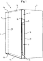
- Fig. 1 shows a perspective schematic representation of a household appliance 1, in particular a refrigerator, with a body 3 and a door attached to it 2.
- the door 2 has a front side 5, the z. B. is formed by a door panel.
- the lower side panel of the door is designated 9a, the upper side panel 9b, and the right and left side panels 8a and 8b.
- the door is hinged to the body 3 on the left side at the two pivot points 6a and 6b, so that a handle for opening the door is necessary on the right side.
- this is formed by a handle insert 10 which is integrated in the right side cheek 8a.
- the handle insert 10 has a recessed grip 12 for the user to intervene.
- the handle insert 10 in the example shown is in three parts, in particular it has an upper end piece 14, including a central part 16 and a lower end piece 15 below.
- the handle insert extends over the entire width of the side cheek 8a, but not in this example over the entire length.
- the upper region of the side cheek 8a is therefore formed by a cover 17.
- the upper region of the side cheek 8a can also be formed by a bent part of the door panel 5.
- the handle insert 10 does not extend over the entire width of the side cheek 8a, and z. B. is inserted into an elongated cutout in the side cheek or the door panel 5 forming the side cheek 8a.
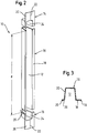
- Fig. 2 the handle insert 10 is the Fig. 1 enlarged and shown in exploded view.
- a middle part 16 of length d can be seen, which is designed as a plastic part with a constant profile, so that different middle parts 16 with different lengths d can be produced in a simple manner from a longer profile piece.
- the profile is essentially U-shaped, so that a recessed grip 12 is formed.
- the middle part 16 closes with a cladding section 18, which, in particular in the case of an insulated door of a refrigerator, closes the interior of the door, which is filled with insulating material, from the outside.
- the upper end piece 14 is designed as a plastic injection-molded part, which can be seen from the seam 22.
- the end piece 14 has a cover section 20 lying on the same plane as the trim section 18.
- the end 24 of the recessed grip 12 is molded into the end piece on the side facing the central part 16.
- the area 24 is thus closed as an upward, downward one however, an open depression is formed, the cross section of which is adapted to the cross section of the profile of the central part 16.
- the lower middle piece 15 is formed mirror-inverted to the end piece 14, which is why the same reference symbols are used to designate the corresponding sections.
- a flange 26 is visible at the lower end piece 15, which runs around the edge of the recessed grip end 24.
- a groove or another shape is preferably introduced, which allows an attachment or another type of positive or non-positive fastening of the middle part 18 to the end piece 15 and on the other side in the end piece 14.
- Fig. 3 shows a cross section through the central part 16 in an enlarged view.
- the essentially U-shaped section 30, which forms the recessed grip 12 is visible. As shown, this can be trapezoidal, but also rectangular or rounded.
- the cover section 18 is arranged on one side and a narrower section 28 on the other side.
- elongated projections 19, 29 can be arranged at the outer ends of these sections, which can serve to engage behind a correspondingly folded-off section of the door panel 5 or the inner shell of the door 2.
- the middle part 16 can also be held on the side cheek in any other way, for. B. by gluing or any positive or non-positive connection.
- a handle insert 10a or 10b is arranged on both the right and left side cheeks of a door 2.
- These handle inserts 10a and 10b are mirror-inverted to each other. However, they each contain the same middle piece 16 and the same end pieces 14, 15.
- the end piece 14, which is arranged on the right side cheek arranged handle insert 10a above is arranged below on the left hand side handle insert 10b.
- the end piece 15 arranged at the bottom on the right side cheek 8a is arranged at the top on the left side cheek 8b.
- the three different components used here can be colored differently, e.g. B. the middle parts 16 colored yellow, the first end piece 14 blue and the second end piece 15 may be colored orange, any other color combination, including metallic colors, being of course also possible.
- the end pieces 14, 15 are produced with two different injection molding tools on the inside simultaneously or successively by steps 31, 32.
- Each of the end pieces 14, 15 can also be multi-part in itself, so that further injection molds may be necessary.
- the end pieces 14, 15 can also have the same shape, so that only a single injection molding machine train is required.
- a handle insert with a first length is produced from two end pieces 14, 15 and a middle part with the length A.
- handle inserts with a second length B are each produced from two end pieces 14, 15 and a middle part with the length B.
- the method allows the production of handle inserts of different lengths in a simple manner, which can be used in different household appliances.
- These pre-assembled handle inserts are then integrated into the side cheek of a door, e.g. B. mounted in a portion of a door panel 5.
Landscapes
- Engineering & Computer Science (AREA)
- Chemical & Material Sciences (AREA)
- Combustion & Propulsion (AREA)
- Mechanical Engineering (AREA)
- General Engineering & Computer Science (AREA)
- Physics & Mathematics (AREA)
- Thermal Sciences (AREA)
- Refrigerator Housings (AREA)
Claims (13)
- Porte (2) pour un appareil ménager (1), notamment pour un appareil frigorifique à usage domestique, une poignée encastrée (10) étant intégrée dans au moins une paroi latérale (8a, 8b) de la porte, la poignée encastrée (10) étant divisée en au moins trois parties (14, 15, 16) en direction longitudinale de la paroi latérale, la poignée encastrée (10) étant assemblée à partir d'une pièce centrale (16) et d'au moins deux pièces terminales (14, 15), caractérisée en ce que l'au moins une pièce centrale (16) de la poignée encastrée est réalisée comme partie d'un profilé extrudé.
- Porte selon la revendication précédente, caractérisée en ce que la poignée encastrée (10) présente une cavité de préhension (12).
- Porte selon l'une quelconque des revendications précédentes, caractérisée en ce que les pièces (14, 15, 16) de la poignée encastrée (10) sont fabriquées en matière plastique.
- Porte selon l'une quelconque des revendications précédentes, caractérisée en ce que les pièces terminales (14, 15) de la poignée encastrée (10) sont réalisées comme pièces en matière plastique moulées par injection.
- Porte selon l'une quelconque des revendications précédentes, caractérisée en ce qu'une poignée encastrée (10a, 10b) est intégrée dans les deux parois latérales (8a, 8b) de la porte.
- Porte selon la revendication 5, caractérisée en ce que les poignées encastrées (10a, 10b) intégrées dans les deux parois latérales (8a, 8b) de la porte (2) sont respectivement réalisées à partir des mêmes pièces terminales (14, 15) et des mêmes pièces centrales (16), la pièce terminale (15) disposée en haut sur la paroi latérale gauche étant disposée en bas sur la paroi latérale droite et vice versa.
- Porte selon l'une quelconque des revendications précédentes, caractérisée en ce que le côté extérieur de la porte (2) est fabriqué à partir d'une tôle de porte (5).
- Porte selon l'une quelconque des revendications précédentes, caractérisée en ce que la poignée encastrée (10) est fixée par adhérence de forme dans la paroi latérale (8a, 8b) de la porte.
- Porte selon l'une quelconque des revendications précédentes, caractérisée en ce que les pièces individuelles (14, 15, 16) de la poignée encastrée (10) sont conçues de couleur différente.
- Appareil ménager (1), notamment réfrigérateur ou congélateur, équipé d'une porte (2) selon l'une quelconque des revendications précédentes.
- Procédé de fabrication d'une poignée encastrée (10) destinée à être insérée dans la paroi latérale (8a, 8b) d'une porte (2) d'un appareil ménager (1), selon l'une quelconque des revendications précédentes 1 à 10, notamment d'un appareil frigorifique à usage domestique, la poignée encastrée étant assemblée à partir d'au moins une pièce centrale (16) et d'au moins deux pièces terminales (14, 15), caractérisé par les étapes suivantes :a) moulage par injection (31, 32) des pièces terminales (14, 15) de la poignée encastrée ;b) extrusion (34) d'un profilé extrudé ;c) coupe en longueur (35) du profilé extrudé pour la fabrication d'une pièce centrale (16) ; etd) assemblage des pièces terminales et de la pièce centrale en une poignée encastrée (10).
- Procédé selon la revendication 11, caractérisé en ce que la poignée encastrée (10) présente deux pièces terminales (14, 15) qui sont respectivement moulées dans des moules d'injection différents.
- Procédé selon la revendication 11 ou 12, caractérisé en ce que la poignée encastrée est réalisée selon l'une quelconque des revendications 1 à 10.
Applications Claiming Priority (2)
| Application Number | Priority Date | Filing Date | Title |
|---|---|---|---|
| DE102009028786A DE102009028786A1 (de) | 2009-08-21 | 2009-08-21 | Tür für ein Haushaltsgerät mit Griffeinsatz |
| PCT/EP2010/061871 WO2011020804A2 (fr) | 2009-08-21 | 2010-08-16 | Porte à poignée rapportée pour un appareil électroménager |
Publications (2)
| Publication Number | Publication Date |
|---|---|
| EP2467657A2 EP2467657A2 (fr) | 2012-06-27 |
| EP2467657B1 true EP2467657B1 (fr) | 2020-02-12 |
Family
ID=43495247
Family Applications (1)
| Application Number | Title | Priority Date | Filing Date |
|---|---|---|---|
| EP10743125.6A Active EP2467657B1 (fr) | 2009-08-21 | 2010-08-16 | Porte à poignée rapportée pour un appareil électroménager |
Country Status (3)
| Country | Link |
|---|---|
| EP (1) | EP2467657B1 (fr) |
| DE (1) | DE102009028786A1 (fr) |
| WO (1) | WO2011020804A2 (fr) |
Cited By (2)
| Publication number | Priority date | Publication date | Assignee | Title |
|---|---|---|---|---|
| EP3992555A1 (fr) * | 2020-11-03 | 2022-05-04 | BSH Hausgeräte GmbH | Porte dotée d'une poignée encastrée de couleur spécifique sur une face marginale de la porte, ainsi qu'appareil électroménager et procédé |
| DE102021125085A1 (de) | 2021-09-28 | 2023-03-30 | Liebherr-Hausgeräte Marica EOOD | Tür für ein Kühl- und/oder Gefriergerät |
Families Citing this family (3)
| Publication number | Priority date | Publication date | Assignee | Title |
|---|---|---|---|---|
| DE102011014285A1 (de) * | 2011-03-17 | 2012-09-20 | BSH Bosch und Siemens Hausgeräte GmbH | Tür, insbesondere für ein Kältegerät |
| DE102015221885A1 (de) * | 2015-11-06 | 2017-05-24 | BSH Hausgeräte GmbH | Tür mit einem Türrahmen und einem Griffmuldenelement sowie Haushaltskältegerät mit einer derartigen Tür |
| DE102020208158A1 (de) * | 2020-06-30 | 2021-12-30 | BSH Hausgeräte GmbH | Haushaltsgerät mit einem Verschlusselement und einer spezifisch geformten Griffmulde an einer Schmalseite des Verschlusselements |
Citations (1)
| Publication number | Priority date | Publication date | Assignee | Title |
|---|---|---|---|---|
| WO2004048723A1 (fr) * | 2002-11-25 | 2004-06-10 | Multibrás S.A. Eletrodomésticos | Ensemble poignee pour la porte avant d'armoires |
Family Cites Families (3)
| Publication number | Priority date | Publication date | Assignee | Title |
|---|---|---|---|---|
| FR1367611A (fr) * | 1963-06-11 | 1964-07-24 | Thomson Houston Comp Francaise | Perfectionnements apportés aux portes de réfrigérateurs |
| DE202006002458U1 (de) * | 2006-02-16 | 2007-06-28 | Liebherr-Hausgeräte Lienz Gmbh | Tür insbesondere für Kühl- und Gefrierschränke |
| DE102007055174A1 (de) * | 2007-11-19 | 2009-05-20 | BSH Bosch und Siemens Hausgeräte GmbH | Tür für ein Kältegerät |
-
2009
- 2009-08-21 DE DE102009028786A patent/DE102009028786A1/de not_active Withdrawn
-
2010
- 2010-08-16 WO PCT/EP2010/061871 patent/WO2011020804A2/fr not_active Ceased
- 2010-08-16 EP EP10743125.6A patent/EP2467657B1/fr active Active
Patent Citations (1)
| Publication number | Priority date | Publication date | Assignee | Title |
|---|---|---|---|---|
| WO2004048723A1 (fr) * | 2002-11-25 | 2004-06-10 | Multibrás S.A. Eletrodomésticos | Ensemble poignee pour la porte avant d'armoires |
Cited By (2)
| Publication number | Priority date | Publication date | Assignee | Title |
|---|---|---|---|---|
| EP3992555A1 (fr) * | 2020-11-03 | 2022-05-04 | BSH Hausgeräte GmbH | Porte dotée d'une poignée encastrée de couleur spécifique sur une face marginale de la porte, ainsi qu'appareil électroménager et procédé |
| DE102021125085A1 (de) | 2021-09-28 | 2023-03-30 | Liebherr-Hausgeräte Marica EOOD | Tür für ein Kühl- und/oder Gefriergerät |
Also Published As
| Publication number | Publication date |
|---|---|
| DE102009028786A1 (de) | 2011-02-24 |
| WO2011020804A3 (fr) | 2011-05-26 |
| WO2011020804A2 (fr) | 2011-02-24 |
| EP2467657A2 (fr) | 2012-06-27 |
Similar Documents
| Publication | Publication Date | Title |
|---|---|---|
| EP2235451B1 (fr) | Conteneur de stockage pour appareil frigorifique | |
| DE102005037891B4 (de) | Türgriff für einen Kühlschrank | |
| EP1599113B1 (fr) | Poignee de porte | |
| EP2464926B1 (fr) | Balconnet pour un appareil de froid | |
| EP2467657B1 (fr) | Porte à poignée rapportée pour un appareil électroménager | |
| DE102008063390A1 (de) | Kältegerät mit einem Ablageboden | |
| WO2012139950A2 (fr) | Jeu de pièces pour une porte d'appareil de froid | |
| DE202010002446U1 (de) | Dachträgeranordnung | |
| EP1397628A1 (fr) | Reservoir a marchandises a refrigerer pour appareil frigorifique | |
| DE202008005350U1 (de) | Abstellbehälter für ein Kältegerät | |
| DE10131829A1 (de) | Gleitfähige Sonnenblende für ein Sonnendach eines Kraftfahrzeuges | |
| EP2457042B1 (fr) | Appareil frigorifique domestique comprenant une clayette, clayette et procédé de fabrication d'une clayette | |
| WO2011124446A2 (fr) | Compartiment de contre-porte pour un appareil frigorifique | |
| DE10259749A1 (de) | Kältegerät und Tür für ein Kältegerät | |
| EP1095232B1 (fr) | Compartiment de rangement | |
| EP3448206A1 (fr) | Glissière latérale pour tiroir | |
| EP2457039A2 (fr) | Porte pour un boitier isolant | |
| EP2464928B1 (fr) | Appareil de froid | |
| EP2023063A2 (fr) | Elément de fermeture de bord de porte d'une porte d'appareil ménager | |
| DE10208063A1 (de) | Türabsteller für ein Kältegerät | |
| DE19654048C2 (de) | Doppelwandiger Behälter mit einer Innenwand und einer Außenwand aus einem thermisch gut leitenden Material, insbesondere für Kühlschränke und Wärmeschränke | |
| WO2012123245A2 (fr) | Porte notamment pour un appareil de froid | |
| DE102005011077A1 (de) | Integration von Griffen und Betätigungen in eine Fahrzeugtür mit einem Kunststoffträgerteil | |
| DE102011007845A1 (de) | Blende für ein Haushaltsgerät sowie Haushaltsgerät | |
| EP1659907B1 (fr) | Boite a cles |
Legal Events
| Date | Code | Title | Description |
|---|---|---|---|
| PUAI | Public reference made under article 153(3) epc to a published international application that has entered the european phase |
Free format text: ORIGINAL CODE: 0009012 |
|
| 17P | Request for examination filed |
Effective date: 20120321 |
|
| AK | Designated contracting states |
Kind code of ref document: A2 Designated state(s): AL AT BE BG CH CY CZ DE DK EE ES FI FR GB GR HR HU IE IS IT LI LT LU LV MC MK MT NL NO PL PT RO SE SI SK SM TR |
|
| DAX | Request for extension of the european patent (deleted) | ||
| RAP1 | Party data changed (applicant data changed or rights of an application transferred) |
Owner name: BSH HAUSGERAETE GMBH |
|
| STAA | Information on the status of an ep patent application or granted ep patent |
Free format text: STATUS: EXAMINATION IS IN PROGRESS |
|
| 17Q | First examination report despatched |
Effective date: 20180329 |
|
| GRAP | Despatch of communication of intention to grant a patent |
Free format text: ORIGINAL CODE: EPIDOSNIGR1 |
|
| STAA | Information on the status of an ep patent application or granted ep patent |
Free format text: STATUS: GRANT OF PATENT IS INTENDED |
|
| INTG | Intention to grant announced |
Effective date: 20190917 |
|
| GRAS | Grant fee paid |
Free format text: ORIGINAL CODE: EPIDOSNIGR3 |
|
| GRAA | (expected) grant |
Free format text: ORIGINAL CODE: 0009210 |
|
| STAA | Information on the status of an ep patent application or granted ep patent |
Free format text: STATUS: THE PATENT HAS BEEN GRANTED |
|
| AK | Designated contracting states |
Kind code of ref document: B1 Designated state(s): AL AT BE BG CH CY CZ DE DK EE ES FI FR GB GR HR HU IE IS IT LI LT LU LV MC MK MT NL NO PL PT RO SE SI SK SM TR |
|
| REG | Reference to a national code |
Ref country code: GB Ref legal event code: FG4D Free format text: NOT ENGLISH |
|
| REG | Reference to a national code |
Ref country code: CH Ref legal event code: EP |
|
| REG | Reference to a national code |
Ref country code: AT Ref legal event code: REF Ref document number: 1232662 Country of ref document: AT Kind code of ref document: T Effective date: 20200215 |
|
| REG | Reference to a national code |
Ref country code: DE Ref legal event code: R096 Ref document number: 502010016481 Country of ref document: DE |
|
| REG | Reference to a national code |
Ref country code: IE Ref legal event code: FG4D Free format text: LANGUAGE OF EP DOCUMENT: GERMAN |
|
| PG25 | Lapsed in a contracting state [announced via postgrant information from national office to epo] |
Ref country code: FI Free format text: LAPSE BECAUSE OF FAILURE TO SUBMIT A TRANSLATION OF THE DESCRIPTION OR TO PAY THE FEE WITHIN THE PRESCRIBED TIME-LIMIT Effective date: 20200212 Ref country code: NO Free format text: LAPSE BECAUSE OF FAILURE TO SUBMIT A TRANSLATION OF THE DESCRIPTION OR TO PAY THE FEE WITHIN THE PRESCRIBED TIME-LIMIT Effective date: 20200512 |
|
| REG | Reference to a national code |
Ref country code: LT Ref legal event code: MG4D |
|
| REG | Reference to a national code |
Ref country code: NL Ref legal event code: MP Effective date: 20200212 |
|
| PG25 | Lapsed in a contracting state [announced via postgrant information from national office to epo] |
Ref country code: GR Free format text: LAPSE BECAUSE OF FAILURE TO SUBMIT A TRANSLATION OF THE DESCRIPTION OR TO PAY THE FEE WITHIN THE PRESCRIBED TIME-LIMIT Effective date: 20200513 Ref country code: BG Free format text: LAPSE BECAUSE OF FAILURE TO SUBMIT A TRANSLATION OF THE DESCRIPTION OR TO PAY THE FEE WITHIN THE PRESCRIBED TIME-LIMIT Effective date: 20200512 Ref country code: HR Free format text: LAPSE BECAUSE OF FAILURE TO SUBMIT A TRANSLATION OF THE DESCRIPTION OR TO PAY THE FEE WITHIN THE PRESCRIBED TIME-LIMIT Effective date: 20200212 Ref country code: IS Free format text: LAPSE BECAUSE OF FAILURE TO SUBMIT A TRANSLATION OF THE DESCRIPTION OR TO PAY THE FEE WITHIN THE PRESCRIBED TIME-LIMIT Effective date: 20200612 Ref country code: SE Free format text: LAPSE BECAUSE OF FAILURE TO SUBMIT A TRANSLATION OF THE DESCRIPTION OR TO PAY THE FEE WITHIN THE PRESCRIBED TIME-LIMIT Effective date: 20200212 Ref country code: LV Free format text: LAPSE BECAUSE OF FAILURE TO SUBMIT A TRANSLATION OF THE DESCRIPTION OR TO PAY THE FEE WITHIN THE PRESCRIBED TIME-LIMIT Effective date: 20200212 |
|
| PG25 | Lapsed in a contracting state [announced via postgrant information from national office to epo] |
Ref country code: NL Free format text: LAPSE BECAUSE OF FAILURE TO SUBMIT A TRANSLATION OF THE DESCRIPTION OR TO PAY THE FEE WITHIN THE PRESCRIBED TIME-LIMIT Effective date: 20200212 |
|
| PG25 | Lapsed in a contracting state [announced via postgrant information from national office to epo] |
Ref country code: ES Free format text: LAPSE BECAUSE OF FAILURE TO SUBMIT A TRANSLATION OF THE DESCRIPTION OR TO PAY THE FEE WITHIN THE PRESCRIBED TIME-LIMIT Effective date: 20200212 Ref country code: DK Free format text: LAPSE BECAUSE OF FAILURE TO SUBMIT A TRANSLATION OF THE DESCRIPTION OR TO PAY THE FEE WITHIN THE PRESCRIBED TIME-LIMIT Effective date: 20200212 Ref country code: EE Free format text: LAPSE BECAUSE OF FAILURE TO SUBMIT A TRANSLATION OF THE DESCRIPTION OR TO PAY THE FEE WITHIN THE PRESCRIBED TIME-LIMIT Effective date: 20200212 Ref country code: SM Free format text: LAPSE BECAUSE OF FAILURE TO SUBMIT A TRANSLATION OF THE DESCRIPTION OR TO PAY THE FEE WITHIN THE PRESCRIBED TIME-LIMIT Effective date: 20200212 Ref country code: RO Free format text: LAPSE BECAUSE OF FAILURE TO SUBMIT A TRANSLATION OF THE DESCRIPTION OR TO PAY THE FEE WITHIN THE PRESCRIBED TIME-LIMIT Effective date: 20200212 Ref country code: SK Free format text: LAPSE BECAUSE OF FAILURE TO SUBMIT A TRANSLATION OF THE DESCRIPTION OR TO PAY THE FEE WITHIN THE PRESCRIBED TIME-LIMIT Effective date: 20200212 Ref country code: CZ Free format text: LAPSE BECAUSE OF FAILURE TO SUBMIT A TRANSLATION OF THE DESCRIPTION OR TO PAY THE FEE WITHIN THE PRESCRIBED TIME-LIMIT Effective date: 20200212 Ref country code: LT Free format text: LAPSE BECAUSE OF FAILURE TO SUBMIT A TRANSLATION OF THE DESCRIPTION OR TO PAY THE FEE WITHIN THE PRESCRIBED TIME-LIMIT Effective date: 20200212 Ref country code: PT Free format text: LAPSE BECAUSE OF FAILURE TO SUBMIT A TRANSLATION OF THE DESCRIPTION OR TO PAY THE FEE WITHIN THE PRESCRIBED TIME-LIMIT Effective date: 20200705 |
|
| REG | Reference to a national code |
Ref country code: DE Ref legal event code: R097 Ref document number: 502010016481 Country of ref document: DE |
|
| PLBE | No opposition filed within time limit |
Free format text: ORIGINAL CODE: 0009261 |
|
| STAA | Information on the status of an ep patent application or granted ep patent |
Free format text: STATUS: NO OPPOSITION FILED WITHIN TIME LIMIT |
|
| 26N | No opposition filed |
Effective date: 20201113 |
|
| PG25 | Lapsed in a contracting state [announced via postgrant information from national office to epo] |
Ref country code: IT Free format text: LAPSE BECAUSE OF FAILURE TO SUBMIT A TRANSLATION OF THE DESCRIPTION OR TO PAY THE FEE WITHIN THE PRESCRIBED TIME-LIMIT Effective date: 20200212 |
|
| PG25 | Lapsed in a contracting state [announced via postgrant information from national office to epo] |
Ref country code: PL Free format text: LAPSE BECAUSE OF FAILURE TO SUBMIT A TRANSLATION OF THE DESCRIPTION OR TO PAY THE FEE WITHIN THE PRESCRIBED TIME-LIMIT Effective date: 20200212 Ref country code: SI Free format text: LAPSE BECAUSE OF FAILURE TO SUBMIT A TRANSLATION OF THE DESCRIPTION OR TO PAY THE FEE WITHIN THE PRESCRIBED TIME-LIMIT Effective date: 20200212 |
|
| PG25 | Lapsed in a contracting state [announced via postgrant information from national office to epo] |
Ref country code: MC Free format text: LAPSE BECAUSE OF FAILURE TO SUBMIT A TRANSLATION OF THE DESCRIPTION OR TO PAY THE FEE WITHIN THE PRESCRIBED TIME-LIMIT Effective date: 20200212 |
|
| REG | Reference to a national code |
Ref country code: CH Ref legal event code: PL |
|
| GBPC | Gb: european patent ceased through non-payment of renewal fee |
Effective date: 20200816 |
|
| PG25 | Lapsed in a contracting state [announced via postgrant information from national office to epo] |
Ref country code: LU Free format text: LAPSE BECAUSE OF NON-PAYMENT OF DUE FEES Effective date: 20200816 Ref country code: LI Free format text: LAPSE BECAUSE OF NON-PAYMENT OF DUE FEES Effective date: 20200831 Ref country code: CH Free format text: LAPSE BECAUSE OF NON-PAYMENT OF DUE FEES Effective date: 20200831 |
|
| REG | Reference to a national code |
Ref country code: BE Ref legal event code: MM Effective date: 20200831 |
|
| PG25 | Lapsed in a contracting state [announced via postgrant information from national office to epo] |
Ref country code: FR Free format text: LAPSE BECAUSE OF NON-PAYMENT OF DUE FEES Effective date: 20200831 |
|
| PG25 | Lapsed in a contracting state [announced via postgrant information from national office to epo] |
Ref country code: BE Free format text: LAPSE BECAUSE OF NON-PAYMENT OF DUE FEES Effective date: 20200831 Ref country code: GB Free format text: LAPSE BECAUSE OF NON-PAYMENT OF DUE FEES Effective date: 20200816 Ref country code: IE Free format text: LAPSE BECAUSE OF NON-PAYMENT OF DUE FEES Effective date: 20200816 |
|
| REG | Reference to a national code |
Ref country code: AT Ref legal event code: MM01 Ref document number: 1232662 Country of ref document: AT Kind code of ref document: T Effective date: 20200816 |
|
| PG25 | Lapsed in a contracting state [announced via postgrant information from national office to epo] |
Ref country code: AT Free format text: LAPSE BECAUSE OF NON-PAYMENT OF DUE FEES Effective date: 20200816 |
|
| PG25 | Lapsed in a contracting state [announced via postgrant information from national office to epo] |
Ref country code: TR Free format text: LAPSE BECAUSE OF FAILURE TO SUBMIT A TRANSLATION OF THE DESCRIPTION OR TO PAY THE FEE WITHIN THE PRESCRIBED TIME-LIMIT Effective date: 20200212 Ref country code: MT Free format text: LAPSE BECAUSE OF FAILURE TO SUBMIT A TRANSLATION OF THE DESCRIPTION OR TO PAY THE FEE WITHIN THE PRESCRIBED TIME-LIMIT Effective date: 20200212 Ref country code: CY Free format text: LAPSE BECAUSE OF FAILURE TO SUBMIT A TRANSLATION OF THE DESCRIPTION OR TO PAY THE FEE WITHIN THE PRESCRIBED TIME-LIMIT Effective date: 20200212 |
|
| PG25 | Lapsed in a contracting state [announced via postgrant information from national office to epo] |
Ref country code: MK Free format text: LAPSE BECAUSE OF FAILURE TO SUBMIT A TRANSLATION OF THE DESCRIPTION OR TO PAY THE FEE WITHIN THE PRESCRIBED TIME-LIMIT Effective date: 20200212 Ref country code: AL Free format text: LAPSE BECAUSE OF FAILURE TO SUBMIT A TRANSLATION OF THE DESCRIPTION OR TO PAY THE FEE WITHIN THE PRESCRIBED TIME-LIMIT Effective date: 20200212 |
|
| PGFP | Annual fee paid to national office [announced via postgrant information from national office to epo] |
Ref country code: DE Payment date: 20220831 Year of fee payment: 13 |
|
| REG | Reference to a national code |
Ref country code: DE Ref legal event code: R084 Ref document number: 502010016481 Country of ref document: DE |
|
| REG | Reference to a national code |
Ref country code: DE Ref legal event code: R119 Ref document number: 502010016481 Country of ref document: DE |
|
| PG25 | Lapsed in a contracting state [announced via postgrant information from national office to epo] |
Ref country code: DE Free format text: LAPSE BECAUSE OF NON-PAYMENT OF DUE FEES Effective date: 20240301 |