EP2467672B1 - Oberflächenausrichtungs- und positionierungsverfahren sowie vorrichtung dafür - Google Patents
Oberflächenausrichtungs- und positionierungsverfahren sowie vorrichtung dafür Download PDFInfo
- Publication number
- EP2467672B1 EP2467672B1 EP10810437.3A EP10810437A EP2467672B1 EP 2467672 B1 EP2467672 B1 EP 2467672B1 EP 10810437 A EP10810437 A EP 10810437A EP 2467672 B1 EP2467672 B1 EP 2467672B1
- Authority
- EP
- European Patent Office
- Prior art keywords
- lens blank
- lens
- laser displacement
- apex
- laser
- Prior art date
- Legal status (The legal status is an assumption and is not a legal conclusion. Google has not performed a legal analysis and makes no representation as to the accuracy of the status listed.)
- Active
Links
Images


Classifications
-
- G—PHYSICS
- G01—MEASURING; TESTING
- G01B—MEASURING LENGTH, THICKNESS OR SIMILAR LINEAR DIMENSIONS; MEASURING ANGLES; MEASURING AREAS; MEASURING IRREGULARITIES OF SURFACES OR CONTOURS
- G01B11/00—Measuring arrangements characterised by the use of optical techniques
- G01B11/24—Measuring arrangements characterised by the use of optical techniques for measuring contours or curvatures
- G01B11/255—Measuring arrangements characterised by the use of optical techniques for measuring contours or curvatures for measuring radius of curvature
-
- G—PHYSICS
- G01—MEASURING; TESTING
- G01M—TESTING STATIC OR DYNAMIC BALANCE OF MACHINES OR STRUCTURES; TESTING OF STRUCTURES OR APPARATUS, NOT OTHERWISE PROVIDED FOR
- G01M11/00—Testing of optical apparatus; Testing structures by optical methods not otherwise provided for
- G01M11/02—Testing optical properties
- G01M11/0221—Testing optical properties by determining the optical axis or position of lenses
Definitions
- This invention relates to a method and apparatus for aligning and positioning a workpiece, such as a lens, so that an axis of the workpiece is precisely aligned with a fixture and a surface of the workpiece is precisely positioned a constant distance from a reference point on the fixture.
- the invention has particular application in the field of manufacturing contact lenses and intraocular lenses, but it not limited to this application.
- the degree of accuracy of alignment of a partially finished lens to its fixture determines the limit of concentricity possible through subsequent machining operations.
- a high degree of concentricity is advantageous in the manufacture of lenses since greater concentricity results in less prism.
- the accuracy of positioning the apex of the lens to a reference point or shoulder of the fixture determines the accuracy of the manufactured lens thickness.
- a high degree of consistency of lens thickness is advantageous for the manufacture of lenses. Such precise positioning, however, can be time consuming and difficult to obtain if done manually.
- U.S. Pat. No. 5,080,482 discloses a method and apparatus for aligning and positioning a lens such that the optical and/or cylinder axis of the lens is precisely aligned with a fixture for the purpose of assembly or further mechanical operations such as machining and polishing. According to another aspect, the lens apex is precisely positioned a constant distance from a reference point.
- a method and apparatus is disclosed for optically aligning and positioning lenses using digitzed video imaging, an X-Y-Z micron stage and a microprocessor (or computer) capable of performing image analysis.
- Contact lenses are typically manufactured by way of a complex multi-step operation whereby the fabricated lens goes through many precision operations.
- the technique described in U.S. Pat. No. 5,080,482 makes use of a camera and a focusing reticle video image in order to automatically align a lens.
- the reticle image is focused on the surface of the lens and then analyzed using a focusing algorithm.
- the process can be time consuming and may be limited to a small range of measurable optical radii.
- a method for determining the apex of a curved surface of a workpiece includes positioning the workpiece in relation to a laser displacement measurement device. Displacement between the laser displacement measurement device and the curved surface is then measured at a series of points on said surface. The apex of the surface may then be calculated based on the interpolated data of such coordinates of the points, including the measured displacement between the laser and the surface.
- an apparatus for determining the apex of a curved surface of a workpiece includes a laser displacement measurement device, a stage for positioning the workpiece in relation to the laser displacement measurement device; and a processor configured to calculate the apex of said surface based on displacement between the laser displacement measurement device and the curved surface at a series of points on said surface.
- a first series of displacements are measured along a first axis perpendicular to the optical axis of the laser displacement measuring device and a second series of displacements are measured along a second axis perpendicular to the first axis and the optical axis of the laser displacement measuring device.
- the first series of displacement measurements define correspond to (x, z) coordinates along a first secant of said surface in an X-Z plane and the second series of displacement measurements define correspond to (y, z) coordinates along a second secant of said surface in an Y-Z plane.
- the (x, y, z) coordinate of the apex are determined and recorded.
- radii of curvature of the surface is also determined.
- the workpiece is a lens blank, which may include a finished base curve surface for a contact lens or an interocular lens.
- the measured apex can be used for lens blocking in which the said lens blank is positioned with respect to a holder such that the axis of said lens blank is in optical alignment with said holder and the finished surface is attached to the holder so that the opposing surface can be machined.
- the laser displacement measuring device is a confocal laser that can measure displacement accurately, preferably within at least 0.0001 millimeters.
- a finished base curve surface is placed in a fixture attached to the X-Y part of an X-Y-Z micron stage.
- a series of laser displacement measurements are obtained by scanning the surface to determine a secant of the surface.
- the X-Y-Z micron stage is rotated 90°, under computer control, and a second set of laser displacement measurements is obtained by scanning the surface to determine a second secant of the surface.
- the scanned displacement measurements are then analyzed to determine the apex of the surface.
- the present invention offers several distinct advantages over the prior art. Specifically, it provides for a greater range of radii that can be aligned and positioned.
- the laser does not have the limitation of focal length of conventional optical systems which may limit the convex radii to 26 mm or steeper.
- the present laser alignment and positioning system is significantly faster, which reduces cycle time and subsequently the cost of manufacturing.
- the present invention also utilizes technology and equipment that can be advantageously employed in a fully automated manufacturing process.
- the lens surface can be aligned, positioned, and blocked by computer control; no manual operations are required. This greatly reduces the cost of manufacture.
- Figures 1a-1d illustrate a conventional blocking operation for a lens.
- the first stage of manufacture forms a polished lens surface 2 on a "blank" 1 of plastic.
- the optical lens is then precisely fixed to a block 3 with a suitable material such as wax or cement 5 so that a second surface of the lens can be machined.
- This stage is commonly referred to as "blocking" the lens.
- the third stage forms a polished optical surface 7 of a fixed diameter on the second surface of the lens 8 thereby forming a contact lens.
- the fourth stage (FIG. Id) involves removing the finished lens and polishing the edges 9 of the lens 10 in a known manner.
- FIG. 2 there is shown an apparatus according to one embodiment of the present invention. Specifically, there is disclosed an alignment and positioning apparatus for aligning and positioning a workpiece in order to enable precise alignment to be performed automatically under computer control without the need for manual alignment.
- a controller 200 such as a computer or microprocessor is provided, which is configured to determine an apex from displacement measurements.
- Controller 200 may include a computer readable storage device and a display device.
- a laser displacement measurement system 204 with an optical axis arranged in the Z-direction.
- This system 204 is configured for highly accurate measurements of displacement in the Z-direction using scanning laser.
- the laser 204 has a preferred minimum displacement measurement accuracy of 0.0001mm, for a lens alignment accuracy of 0.003mm to 0.005mm.
- the preferred beam width of the laser is 0.002 mm. Larger beam widths may be used with a resulting effect on the displacement measurement accuracy of steeper radii.
- the laser system may comprise a confocal laser system, such as a Keyence measuring unit LT-9010M.
- a chuck or other suitable holding structure 206 for holding a block 208, and a workpiece 8, such as a lens, attached to a fixture assembly 210.
- Fixture assembly 210 is operably connected to the X-Y axis of the X-Y-Z micron stage 212.
- the chuck 206 is mounted to the side a predetermined distance from the laser axis and mechanically aligned so as to be parallel to the laser axis.
- the laser generates a series of displacement measurements by scanning the lens surface, the data is stored, and the scan is repeated at a rotation of 90° compared to the previous scan.
- the second set of data is stored, and an analysis is performed to determine the apex height (Z-position) and lens center (X,Y coordinates) using the two sets of displacement.
- various digital analysis techniques may be used. Possible techniques include scans utilizing a fewer or greater number of displacement measurement data points and/or scans performed at faster or slower speeds. Both the number of data points, length of scan, and scan speed can increase or decrease accuracy versus speed depending on the application.
- the centering operation determines the exact apex center line of the lens and the apex height of the lens. After these positions are determined and information corresponding to the respective positions is stored in a computer readable storage device of controller 200, the block may be inserted into chuck 206 and hot wax is deposited onto the lens surface. The computer then moves the Z-axis down to a point above the lens, which allows the apex to be fixed at the desired distance from the reference position, based on the information stored in the computer. Once any desired operations have been performed, the computer moves the Z-axis away so that the lens, which is now fixed to the block, can be removed and the process repeated for the next lens.
- FIG. 3 is a flow chart illustrating operation of an alignment system according to an embodiment of the present invention.
- the lens is inserted into a holder connected to the X-Y part of the X-Y-Z micron stage and positioned under the laser displacement device (302).
- a distance between the laser and the device along the Z-axis is measured by scanning the surface of the lens with a predetermined beam distance (304). The distance measurement is verified (306).
- the laser is moved a predetermined distance (in this example, 0.5 mm) closer to the lens (307). This process is repeated until a range of displacement measurements are obtained.
- the distance between the laser and the lens is then adjusted to a distance in the middle of the range (308).
- the relative displacement of the laser and the lens is then moved along the X-axis in a direction opposite the scan direction by a predetermined distance, in this example, half the scan distance of the laser (310).
- the relative distance is adjusted along the X-axis by the scan distance and the displacement between the laser and the lens surface along the Z-axis is then recorded along with the position on the X axis (312).
- the three coefficients ( a0, a1, a2 ) are chosen to minimize the mean squared error.
- the center X position of the lens is then given by the root of the first derivative of the fit function (314).
- the relative displacement of the lens and the laser in the X-direction is adjusted so that the lens is centered at the calculated center X position (318).
- the relative displacement between the laser and the part is adjusted in the Y-direction by moving the lens half the scan distance opposite to the scan direction (322).
- the relative displacement in the Y direction is then adjusted by the prescribed scan distance and the distance in the z direction and y position is recorded along a certain interval to obtain a series of (y,z) pairs (324).
- a curve of the surface of the lens in the Y-Z plane is then determined by fitting a quadratic function to the recorded (y,z) pairs, and the coefficients of the quadratic equation are chosen to minimize the mse (326).
- the lens' center Y position is then given by the root of the first derivative of the fit function (328).
- the lens is moved to the calculated center Y position (330) and it is verified whether this position is within the predetermined potion of the scan range, in this example, the middle 30% (332). If this is not the case, the process is repeated to determine the curve of the surface along the Y-Z plane. Otherwise, the lens is centered in the center X and center Y position that corresponds to the apex and the displacement in the Z direction is determined to find the z coordinate for the apex (334).
- the apex of the lens may be determined precisely by measuring points along the surface of the part to define at least two secants.
- the scan consists of taking a series of displacement measurements along a curve of the surface of the lens with the laser in order to determine a secant.
- the lens surface is scanned a second time, after being rotated 90° with respect to the first scan by way of computer controlled manipulation of the X and Y axis.
- the scan consists of taking a series of displacement measurements along a curve of the surface of the lens with the laser in order to determine a secant.
- the apex height is calculated and the Z-position recorded.
- the (x,y) coordinates of the apex are also calculated and recorded.
- relative displacement between the laser and the lens may be adjusted by moving either the laser or the lens.
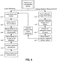
- optical radius measurement may be performed according to the technique described in U.S. Patent No. 5,080,482 .
- Such process includes obtaining a reflected image from the lens surface (416) and centering the image in the X-Y plane (418).
- the reflected image is focused (420) and the best Z-position (i.e., optical radius value) is determined (422).
- Blocking may include loading a block into a holder (402) and applying wax or other suitable material to the lens surface (404). The block is then positioned at the (x,y) coordinates of the apex (406). The block is then moved along the Z-axis to a fix distance(408) at which desired operations may be performed (410). The lens may be fixed to the block and removed (412). In this manner, the lens can be fixed to the block with great alignment precision between the lens apex that the block so that the opposing surface of the lens can be machined.
Landscapes
- Physics & Mathematics (AREA)
- General Physics & Mathematics (AREA)
- Chemical & Material Sciences (AREA)
- Analytical Chemistry (AREA)
- Length Measuring Devices By Optical Means (AREA)
Claims (15)
- Ein Verfahren zum Positionieren eines Linsenrohlings (8) auf einem Block (208), umfassend:das Positionieren des Linsenrohlings (8) bezüglich einer Laser-Wegmessvorrichtung (204) derart, dass eine konkave Oberfläche des Linsenrohlings (8) der Laser-Wegmessvorrichtung gegenüberliegt;das Messen einer Verschiebung zwischen der Laser-Wegmessvorrichtung (204) und der konkaven Oberfläche, um Positionen einer Reihe von Punkten auf der konkaven Oberfläche zu bestimmen;das Bestimmen einer Scheitelmittellinie und einer Scheitelposition des Linsenrohlings (8) auf der Basis der bestimmten Positionen der Punkte; unddas Anbringen des Blocks (208) am Linsenrohling (8) derart, dass die Scheitelmittellinie des Linsenrohlings (8) mit einer Achse des Blocks (208) ausgerichtet und die Scheitelposition in einem vorgegebenen Abstand von einem Bezugspunkt auf dem Block (208) fixiert ist.
- Das Verfahren nach Anspruch 1, wobei das Messen der Verschiebung das Messen einer ersten Reihe von Verschiebungen entlang einer ersten Achse senkrecht zur optischen Achse der Laser-Wegmessvorrichtung (204) und das Messen einer zweiten Reihe von Verschiebungen entlang einer zweiten Achse senkrecht zur ersten Achse und zur optischen Achse der Laser-Wegmessvorrichtung (204) umfasst.
- Das Verfahren nach Anspruch 2, wobei die erste Reihe von Verschiebungsmessungen (x, z)-Koordinaten entlang einer ersten Sekante der genannten Oberfläche in einer X-Z-Ebene und die zweite Reihe von Verschiebungsmessungen (y, z)-Koordinaten entlang einer zweiten Sekante der genannten Oberfläche in einer Y-Z-Ebene definieren.
- Das Verfahren nach Anspruch 3, wobei das Bestimmen der Scheitelposition das Bestimmen der (x, y, z)-Koordinaten des Scheitels der genannten konkaven Oberfläche umfasst.
- Das Verfahren nach Anspruch 1, weiter umfassend das Bestimmen von Krümmungsradien der genannten konkaven Oberfläche.
- Das Verfahren nach Anspruch 1, wobei der Linsenrohling (8) ein Kontaktlinsenrohling oder ein Interokularlinsenrohling ist.
- Das Verfahren nach Anspruch 1, wobei die Laser-Wegmessvorrichtung (204) ein konfokaler Laser ist.
- Das Verfahren nach Anspruch 7, wobei die Laser-Wegmessvorrichtung (204) Verschiebungen mit einer Genauigkeit von mindestens 0.0001 Millimeter misst.
- Eine Vorrichtung zum Positionieren eines Linsenrohlings (8) auf einem Block (208), umfassend:eine Plattform (212); undeinen Prozessor (200);gekennzeichnet durch:eine Laser-Wegmessvorrichtung (204),wobei die Plattform (212) dazu ausgebildet ist, den Linsenrohling (8) bezüglich der Laser-Wegmessvorrichtung (204) derart zu positionieren, dass eine konkave Oberfläche des Linsenrohlings (8) der Laser-Wegmessvorrichtung (204) gegenüberliegt, wobei die Laser-Wegmessvorrichtung (204) dazu ausgebildet ist, Verschiebungen zwischen der Laser-Wegmessvorrichtung (204) und der konkaven Oberfläche zu messen; undder Prozessort (200) dazu ausgebildet ist:die Positionen einer Reihe von Punkten auf der konkaven Oberfläche zu bestimmen,eine Scheitelmittellinie und eine Scheitelposition des Linsenrohlings auf der Basis der bestimmten Positionen der Punkte zu bestimmen, undden Block (208) zur Anbringung des Blocks (208) am Linsenrohling (8) derart zu positionieren, dass die Scheitelmittellinie des Linsenrohlings (8) mit einer Achse des Blocks (208) ausgerichtet und die Scheitelposition in einem vorgegebenen Abstand von einem Bezugspunkt auf dem Block (208) fixiert ist.
- Die Vorrichtung nach Anspruch 9, wobei der Prozessor (200) weiter dazu ausgebildet ist, die relative Position des Linsenrohlings (8) bezüglich der Laser-Wegmessvorrichtung (204) einzustellen, eine erste Reihe von Verschiebungen entlang einer ersten Achse senkrecht zur optischen Achse der Laser-Wegmessvorrichtung (204) aufzuzeichnen eine zweite Reihe von Verschiebungen entlang einer zweiten Achse senkrecht zur ersten Achse und zur optischen Achse der Laser-Wegmessvorrichtung (204) aufzuzeichnen.
- Die Vorrichtung nach Anspruch 10, wobei die erste Reihe von Verschiebungsmessungen (x, z)-Koordinaten entlang einer ersten Sekante der genannten Oberfläche in einer X-Z-Ebene und die zweite Reihe von Verschiebungsmessungen (y, z)-Koordinaten entlang einer zweiten Sekante der genannten Oberfläche in einer Y-Z-Ebene definieren.
- Die Vorrichtung nach Anspruch 11, wobei das Bestimmen der Scheitelposition das Bestimmen der (x, y, z)-Koordinaten des Scheitels der genannten konkaven Oberfläche umfasst.
- Die Vorrichtung nach Anspruch 9, weiter umfassend das Bestimmen von Krümmungsradien der genannten konkaven Oberfläche.
- Die Vorrichtung nach Anspruch 9, wobei die Laser-Wegmessvorrichtung (204) ein konfokaler Laser ist.
- Die Vorrichtung nach Anspruch 14, wobei die Laser-Wegmessvorrichtung (204) dazu ausgebildet ist, Verschiebungen mit einer Genauigkeit von mindestens 0.0001 Millimeter zu messen.
Applications Claiming Priority (2)
| Application Number | Priority Date | Filing Date | Title |
|---|---|---|---|
| US12/544,116 US8184301B2 (en) | 2009-08-19 | 2009-08-19 | Surface alignment and positioning method and apparatus |
| PCT/US2010/045591 WO2011022322A1 (en) | 2009-08-19 | 2010-08-16 | Surface alignment and positioning method and apparatus |
Publications (3)
| Publication Number | Publication Date |
|---|---|
| EP2467672A1 EP2467672A1 (de) | 2012-06-27 |
| EP2467672A4 EP2467672A4 (de) | 2017-11-15 |
| EP2467672B1 true EP2467672B1 (de) | 2022-03-23 |
Family
ID=43605138
Family Applications (1)
| Application Number | Title | Priority Date | Filing Date |
|---|---|---|---|
| EP10810437.3A Active EP2467672B1 (de) | 2009-08-19 | 2010-08-16 | Oberflächenausrichtungs- und positionierungsverfahren sowie vorrichtung dafür |
Country Status (3)
| Country | Link |
|---|---|
| US (1) | US8184301B2 (de) |
| EP (1) | EP2467672B1 (de) |
| WO (1) | WO2011022322A1 (de) |
Families Citing this family (6)
| Publication number | Priority date | Publication date | Assignee | Title |
|---|---|---|---|---|
| US9457194B2 (en) * | 2011-02-21 | 2016-10-04 | Advanced Neuromodulation Systems, Inc. | Method for fabricating an implantable lead for applying electrical pulses to tissue of a patient and system for fabrication thereof |
| US8570537B1 (en) | 2012-10-26 | 2013-10-29 | Nissan North America, Inc. | Method for bore chamfer measurement |
| CN103837093B (zh) * | 2012-11-20 | 2017-09-12 | 鸿富锦精密工业(深圳)有限公司 | 光谱共焦传感器校准系统及方法 |
| CN112247671B (zh) * | 2020-11-05 | 2022-04-19 | 深圳数马电子技术有限公司 | 一种柱体工件的分中方法以及装置 |
| CN115031679B (zh) * | 2022-08-09 | 2022-11-18 | 四川至臻光电有限公司 | 一种用于光学元件检测的调心方法、装置及系统 |
| CN116499437A (zh) * | 2023-05-25 | 2023-07-28 | 江苏兴达钢帘线股份有限公司 | 一种校直器工装的装配检测装置 |
Family Cites Families (24)
| Publication number | Priority date | Publication date | Assignee | Title |
|---|---|---|---|---|
| US4084458A (en) * | 1973-10-06 | 1978-04-18 | Global Vision (U.K.) Limited | Manufacture of contact lenses |
| DD274962A3 (de) * | 1976-10-14 | 1990-01-10 | Fritz Mahler | Verfahren zur messung des abstandes von linsenscheiteln zu werkzeugarbeitsflaechen |
| US4149801A (en) * | 1977-02-17 | 1979-04-17 | David Volk | Method and apparatus for measuring aspheric contact lens surfaces |
| GB8603391D0 (en) * | 1986-02-12 | 1986-03-19 | British Aerospace | Position sensor |
| US5080482A (en) * | 1990-05-29 | 1992-01-14 | Benz Research And Development Corporation | Lens alignment and positioning method and apparatus |
| IT1258488B (it) * | 1992-09-23 | 1996-02-26 | Renzo Mattioli | Apparecchio per l'analisi topografica di superfici anatomiche, in particolare della cornea |
| ES2132666T3 (es) * | 1994-05-28 | 1999-08-16 | Roke Manor Research | Perfeccionamientos relativos a un aparato para medir la curvatura de superficies. |
| TW277013B (de) * | 1994-07-29 | 1996-06-01 | Hitachi Shipbuilding Eng Co | |
| US5794498A (en) * | 1994-10-19 | 1998-08-18 | Taylor Hobson Limited | In-situ method and apparatus for blocking lenses |
| JP3335826B2 (ja) * | 1995-12-05 | 2002-10-21 | 株式会社日立製作所 | はんだバンプの測定装置 |
| US5760906A (en) * | 1995-12-27 | 1998-06-02 | Technology Research Association Of Medical And Welfare Apparatus | Shape measurement apparatus and method |
| DE19702287C2 (de) * | 1997-01-23 | 1999-02-11 | Wernicke & Co Gmbh | Verfahren zum Ermitteln des Facettenverlaufs auf dem Rand von formzubearbeitenden Brillengläsern und zum Steuern des Formbearbeitens entsprechend dem ermittelten Facettenverlauf |
| US6051844A (en) * | 1997-08-08 | 2000-04-18 | Au; Henry H. | Scanning system for rapid thermal cycle stress/curvature measurement |
| JP2001237596A (ja) * | 2000-02-24 | 2001-08-31 | Matsushita Electric Ind Co Ltd | 電子部品実装装置および電子部品実装方法 |
| KR100421427B1 (ko) * | 2001-01-11 | 2004-03-09 | 한국과학기술원 | 공초점원리의 단위변위센서를 이용한 초정밀 변위측정기및 다양한 변위측정방법 |
| JP4101543B2 (ja) * | 2002-03-26 | 2008-06-18 | 株式会社トーメー | 眼用レンズの厚み測定方法 |
| US20050140981A1 (en) * | 2002-04-18 | 2005-06-30 | Rudolf Waelti | Measurement of optical properties |
| WO2004098396A2 (en) * | 2003-05-01 | 2004-11-18 | The Cleveland Clinic Foundation | Method and apparatus for measuring a retinal sublayer characteristic |
| JP4794160B2 (ja) * | 2004-03-31 | 2011-10-19 | 日東電工株式会社 | 表面形状測定装置および表面形状測定方法 |
| WO2006065437A2 (en) * | 2004-11-12 | 2006-06-22 | Rvsi Inspection Llc | Laser triangulation method for measurement of highly reflective solder balls |
| WO2007018118A1 (ja) * | 2005-08-05 | 2007-02-15 | Mitaka Kohki Co., Ltd. | レンズにおける表裏面の光軸偏芯量の測定方法 |
| JP2007121122A (ja) * | 2005-10-28 | 2007-05-17 | Omron Corp | 変位センサ |
| JP4930052B2 (ja) * | 2006-02-15 | 2012-05-09 | 住友電気工業株式会社 | GaN基板の裏面の反り測定方法 |
| JP4885762B2 (ja) * | 2007-02-27 | 2012-02-29 | 株式会社ディスコ | チャックテーブルに保持された被加工物の計測装置およびレーザー加工機 |
-
2009
- 2009-08-19 US US12/544,116 patent/US8184301B2/en active Active
-
2010
- 2010-08-16 EP EP10810437.3A patent/EP2467672B1/de active Active
- 2010-08-16 WO PCT/US2010/045591 patent/WO2011022322A1/en not_active Ceased
Also Published As
| Publication number | Publication date |
|---|---|
| EP2467672A4 (de) | 2017-11-15 |
| WO2011022322A1 (en) | 2011-02-24 |
| EP2467672A1 (de) | 2012-06-27 |
| US20110043829A1 (en) | 2011-02-24 |
| US8184301B2 (en) | 2012-05-22 |
Similar Documents
| Publication | Publication Date | Title |
|---|---|---|
| US10612907B2 (en) | Device and method for measuring workpieces | |
| EP1719584B1 (de) | Verfahren für die automatische Kalibrierung der Werkzeuge in einer Drehmaschine benutzt für die Herstellung von insbesondere Brillenlinsen | |
| KR100869110B1 (ko) | 형상 측정 장치 및 방법, 및 피측정물의 제조 방법 | |
| EP2467672B1 (de) | Oberflächenausrichtungs- und positionierungsverfahren sowie vorrichtung dafür | |
| US8467042B2 (en) | Lens shape measuring apparatus and the method thereof, manufacturing method of spectacle lens, and manufacturing method of spectacles | |
| EP2399097B1 (de) | Verfahren zum berührungslosen messen der topografie | |
| EP1555561B1 (de) | Berührungsloses Messsystem für sphärische und asphärische Oberflächen und Methode zur Benutzung | |
| JP7259111B2 (ja) | 物体の少なくとも1つの寸法を測定する方法 | |
| CN102645202B (zh) | 大口径非球面工件轮廓的测量方法 | |
| CN101408412A (zh) | 三维形状测量方法 | |
| CN210773918U (zh) | 非接触式透镜中心厚度测量装置 | |
| CN109406105B (zh) | 虚像检测方法及检测系统 | |
| KR20110065365A (ko) | 비구면체 측정 방법 및 장치 | |
| Langehanenberg et al. | Smart and precise alignment of optical systems | |
| JP5853167B2 (ja) | レンズ測定装置、レンズ測定方法及びレンズ製造方法 | |
| CN104776804A (zh) | 基于非接触式微小距离测量的光学相机装调方法及装置 | |
| JP4311952B2 (ja) | 3次元座標測定方法 | |
| JP3317100B2 (ja) | 光コネクタ研磨面自動検査装置及び光コネクタ研磨面検査法 | |
| CN111288933A (zh) | 一种球面或旋转对称非球面光学元件自动定心方法 | |
| EP1033553A2 (de) | Verfahren und Apparat zur Messung einer aspherischen Form und Hestellungsverfahren eines optischen Elements unter ihrer Anwendung | |
| CN114659756A (zh) | 光学元件光学定心可视化在线检测装置及方法 | |
| JPH11281306A (ja) | 座標測定機の校正値検出方法及びこの校正値を用いた形状データ校正方法 | |
| JP2022026771A (ja) | 非接触真円度及び直径測定方法 | |
| JPH10221027A (ja) | ビデオ式非接触伸び計 | |
| CN114485533A (zh) | 一种二次曲面光学元件的轴心测量装置及方法 |
Legal Events
| Date | Code | Title | Description |
|---|---|---|---|
| PUAI | Public reference made under article 153(3) epc to a published international application that has entered the european phase |
Free format text: ORIGINAL CODE: 0009012 |
|
| 17P | Request for examination filed |
Effective date: 20120314 |
|
| AK | Designated contracting states |
Kind code of ref document: A1 Designated state(s): AL AT BE BG CH CY CZ DE DK EE ES FI FR GB GR HR HU IE IS IT LI LT LU LV MC MK MT NL NO PL PT RO SE SI SK SM TR |
|
| DAX | Request for extension of the european patent (deleted) | ||
| RA4 | Supplementary search report drawn up and despatched (corrected) |
Effective date: 20171017 |
|
| RIC1 | Information provided on ipc code assigned before grant |
Ipc: G01B 11/255 20060101AFI20171011BHEP Ipc: G01M 11/02 20060101ALN20171011BHEP |
|
| STAA | Information on the status of an ep patent application or granted ep patent |
Free format text: STATUS: EXAMINATION IS IN PROGRESS |
|
| 17Q | First examination report despatched |
Effective date: 20200511 |
|
| RIC1 | Information provided on ipc code assigned before grant |
Ipc: G01M 11/02 20060101ALN20210310BHEP Ipc: G01B 11/255 20060101AFI20210310BHEP |
|
| RIC1 | Information provided on ipc code assigned before grant |
Ipc: G01M 11/02 20060101ALN20210312BHEP Ipc: G01B 11/255 20060101AFI20210312BHEP |
|
| GRAP | Despatch of communication of intention to grant a patent |
Free format text: ORIGINAL CODE: EPIDOSNIGR1 |
|
| STAA | Information on the status of an ep patent application or granted ep patent |
Free format text: STATUS: GRANT OF PATENT IS INTENDED |
|
| RIC1 | Information provided on ipc code assigned before grant |
Ipc: G01M 11/02 20060101ALN20210408BHEP Ipc: G01B 11/255 20060101AFI20210408BHEP |
|
| INTG | Intention to grant announced |
Effective date: 20210430 |
|
| GRAJ | Information related to disapproval of communication of intention to grant by the applicant or resumption of examination proceedings by the epo deleted |
Free format text: ORIGINAL CODE: EPIDOSDIGR1 |
|
| STAA | Information on the status of an ep patent application or granted ep patent |
Free format text: STATUS: EXAMINATION IS IN PROGRESS |
|
| REG | Reference to a national code |
Ref country code: DE Ref legal event code: R079 Ref document number: 602010068132 Country of ref document: DE Free format text: PREVIOUS MAIN CLASS: G01B0011240000 Ipc: G01B0011255000 |
|
| INTC | Intention to grant announced (deleted) | ||
| GRAP | Despatch of communication of intention to grant a patent |
Free format text: ORIGINAL CODE: EPIDOSNIGR1 |
|
| STAA | Information on the status of an ep patent application or granted ep patent |
Free format text: STATUS: GRANT OF PATENT IS INTENDED |
|
| RIC1 | Information provided on ipc code assigned before grant |
Ipc: G01M 11/02 20060101ALN20210909BHEP Ipc: G01B 11/255 20060101AFI20210909BHEP |
|
| INTG | Intention to grant announced |
Effective date: 20211006 |
|
| GRAS | Grant fee paid |
Free format text: ORIGINAL CODE: EPIDOSNIGR3 |
|
| GRAA | (expected) grant |
Free format text: ORIGINAL CODE: 0009210 |
|
| STAA | Information on the status of an ep patent application or granted ep patent |
Free format text: STATUS: THE PATENT HAS BEEN GRANTED |
|
| AK | Designated contracting states |
Kind code of ref document: B1 Designated state(s): AL AT BE BG CH CY CZ DE DK EE ES FI FR GB GR HR HU IE IS IT LI LT LU LV MC MK MT NL NO PL PT RO SE SI SK SM TR |
|
| REG | Reference to a national code |
Ref country code: GB Ref legal event code: FG4D |
|
| REG | Reference to a national code |
Ref country code: CH Ref legal event code: EP |
|
| REG | Reference to a national code |
Ref country code: DE Ref legal event code: R096 Ref document number: 602010068132 Country of ref document: DE |
|
| REG | Reference to a national code |
Ref country code: IE Ref legal event code: FG4D |
|
| REG | Reference to a national code |
Ref country code: AT Ref legal event code: REF Ref document number: 1477724 Country of ref document: AT Kind code of ref document: T Effective date: 20220415 |
|
| REG | Reference to a national code |
Ref country code: LT Ref legal event code: MG9D |
|
| REG | Reference to a national code |
Ref country code: NL Ref legal event code: MP Effective date: 20220323 |
|
| PG25 | Lapsed in a contracting state [announced via postgrant information from national office to epo] |
Ref country code: SE Free format text: LAPSE BECAUSE OF FAILURE TO SUBMIT A TRANSLATION OF THE DESCRIPTION OR TO PAY THE FEE WITHIN THE PRESCRIBED TIME-LIMIT Effective date: 20220323 Ref country code: NO Free format text: LAPSE BECAUSE OF FAILURE TO SUBMIT A TRANSLATION OF THE DESCRIPTION OR TO PAY THE FEE WITHIN THE PRESCRIBED TIME-LIMIT Effective date: 20220623 Ref country code: LT Free format text: LAPSE BECAUSE OF FAILURE TO SUBMIT A TRANSLATION OF THE DESCRIPTION OR TO PAY THE FEE WITHIN THE PRESCRIBED TIME-LIMIT Effective date: 20220323 Ref country code: HR Free format text: LAPSE BECAUSE OF FAILURE TO SUBMIT A TRANSLATION OF THE DESCRIPTION OR TO PAY THE FEE WITHIN THE PRESCRIBED TIME-LIMIT Effective date: 20220323 Ref country code: BG Free format text: LAPSE BECAUSE OF FAILURE TO SUBMIT A TRANSLATION OF THE DESCRIPTION OR TO PAY THE FEE WITHIN THE PRESCRIBED TIME-LIMIT Effective date: 20220623 |
|
| REG | Reference to a national code |
Ref country code: AT Ref legal event code: MK05 Ref document number: 1477724 Country of ref document: AT Kind code of ref document: T Effective date: 20220323 |
|
| PG25 | Lapsed in a contracting state [announced via postgrant information from national office to epo] |
Ref country code: LV Free format text: LAPSE BECAUSE OF FAILURE TO SUBMIT A TRANSLATION OF THE DESCRIPTION OR TO PAY THE FEE WITHIN THE PRESCRIBED TIME-LIMIT Effective date: 20220323 Ref country code: GR Free format text: LAPSE BECAUSE OF FAILURE TO SUBMIT A TRANSLATION OF THE DESCRIPTION OR TO PAY THE FEE WITHIN THE PRESCRIBED TIME-LIMIT Effective date: 20220624 Ref country code: FI Free format text: LAPSE BECAUSE OF FAILURE TO SUBMIT A TRANSLATION OF THE DESCRIPTION OR TO PAY THE FEE WITHIN THE PRESCRIBED TIME-LIMIT Effective date: 20220323 |
|
| PG25 | Lapsed in a contracting state [announced via postgrant information from national office to epo] |
Ref country code: NL Free format text: LAPSE BECAUSE OF FAILURE TO SUBMIT A TRANSLATION OF THE DESCRIPTION OR TO PAY THE FEE WITHIN THE PRESCRIBED TIME-LIMIT Effective date: 20220323 |
|
| PG25 | Lapsed in a contracting state [announced via postgrant information from national office to epo] |
Ref country code: SM Free format text: LAPSE BECAUSE OF FAILURE TO SUBMIT A TRANSLATION OF THE DESCRIPTION OR TO PAY THE FEE WITHIN THE PRESCRIBED TIME-LIMIT Effective date: 20220323 Ref country code: SK Free format text: LAPSE BECAUSE OF FAILURE TO SUBMIT A TRANSLATION OF THE DESCRIPTION OR TO PAY THE FEE WITHIN THE PRESCRIBED TIME-LIMIT Effective date: 20220323 Ref country code: RO Free format text: LAPSE BECAUSE OF FAILURE TO SUBMIT A TRANSLATION OF THE DESCRIPTION OR TO PAY THE FEE WITHIN THE PRESCRIBED TIME-LIMIT Effective date: 20220323 Ref country code: PT Free format text: LAPSE BECAUSE OF FAILURE TO SUBMIT A TRANSLATION OF THE DESCRIPTION OR TO PAY THE FEE WITHIN THE PRESCRIBED TIME-LIMIT Effective date: 20220725 Ref country code: ES Free format text: LAPSE BECAUSE OF FAILURE TO SUBMIT A TRANSLATION OF THE DESCRIPTION OR TO PAY THE FEE WITHIN THE PRESCRIBED TIME-LIMIT Effective date: 20220323 Ref country code: EE Free format text: LAPSE BECAUSE OF FAILURE TO SUBMIT A TRANSLATION OF THE DESCRIPTION OR TO PAY THE FEE WITHIN THE PRESCRIBED TIME-LIMIT Effective date: 20220323 Ref country code: CZ Free format text: LAPSE BECAUSE OF FAILURE TO SUBMIT A TRANSLATION OF THE DESCRIPTION OR TO PAY THE FEE WITHIN THE PRESCRIBED TIME-LIMIT Effective date: 20220323 Ref country code: AT Free format text: LAPSE BECAUSE OF FAILURE TO SUBMIT A TRANSLATION OF THE DESCRIPTION OR TO PAY THE FEE WITHIN THE PRESCRIBED TIME-LIMIT Effective date: 20220323 |
|
| PG25 | Lapsed in a contracting state [announced via postgrant information from national office to epo] |
Ref country code: PL Free format text: LAPSE BECAUSE OF FAILURE TO SUBMIT A TRANSLATION OF THE DESCRIPTION OR TO PAY THE FEE WITHIN THE PRESCRIBED TIME-LIMIT Effective date: 20220323 Ref country code: IS Free format text: LAPSE BECAUSE OF FAILURE TO SUBMIT A TRANSLATION OF THE DESCRIPTION OR TO PAY THE FEE WITHIN THE PRESCRIBED TIME-LIMIT Effective date: 20220723 Ref country code: AL Free format text: LAPSE BECAUSE OF FAILURE TO SUBMIT A TRANSLATION OF THE DESCRIPTION OR TO PAY THE FEE WITHIN THE PRESCRIBED TIME-LIMIT Effective date: 20220323 |
|
| REG | Reference to a national code |
Ref country code: DE Ref legal event code: R097 Ref document number: 602010068132 Country of ref document: DE |
|
| PLBE | No opposition filed within time limit |
Free format text: ORIGINAL CODE: 0009261 |
|
| STAA | Information on the status of an ep patent application or granted ep patent |
Free format text: STATUS: NO OPPOSITION FILED WITHIN TIME LIMIT |
|
| PG25 | Lapsed in a contracting state [announced via postgrant information from national office to epo] |
Ref country code: DK Free format text: LAPSE BECAUSE OF FAILURE TO SUBMIT A TRANSLATION OF THE DESCRIPTION OR TO PAY THE FEE WITHIN THE PRESCRIBED TIME-LIMIT Effective date: 20220323 |
|
| 26N | No opposition filed |
Effective date: 20230102 |
|
| PG25 | Lapsed in a contracting state [announced via postgrant information from national office to epo] |
Ref country code: MC Free format text: LAPSE BECAUSE OF FAILURE TO SUBMIT A TRANSLATION OF THE DESCRIPTION OR TO PAY THE FEE WITHIN THE PRESCRIBED TIME-LIMIT Effective date: 20220323 |
|
| REG | Reference to a national code |
Ref country code: CH Ref legal event code: PL |
|
| PG25 | Lapsed in a contracting state [announced via postgrant information from national office to epo] |
Ref country code: LU Free format text: LAPSE BECAUSE OF NON-PAYMENT OF DUE FEES Effective date: 20220816 Ref country code: LI Free format text: LAPSE BECAUSE OF NON-PAYMENT OF DUE FEES Effective date: 20220831 Ref country code: CH Free format text: LAPSE BECAUSE OF NON-PAYMENT OF DUE FEES Effective date: 20220831 |
|
| REG | Reference to a national code |
Ref country code: BE Ref legal event code: MM Effective date: 20220831 |
|
| PG25 | Lapsed in a contracting state [announced via postgrant information from national office to epo] |
Ref country code: SI Free format text: LAPSE BECAUSE OF FAILURE TO SUBMIT A TRANSLATION OF THE DESCRIPTION OR TO PAY THE FEE WITHIN THE PRESCRIBED TIME-LIMIT Effective date: 20220323 |
|
| P01 | Opt-out of the competence of the unified patent court (upc) registered |
Effective date: 20230516 |
|
| PG25 | Lapsed in a contracting state [announced via postgrant information from national office to epo] |
Ref country code: IT Free format text: LAPSE BECAUSE OF FAILURE TO SUBMIT A TRANSLATION OF THE DESCRIPTION OR TO PAY THE FEE WITHIN THE PRESCRIBED TIME-LIMIT Effective date: 20220323 Ref country code: IE Free format text: LAPSE BECAUSE OF NON-PAYMENT OF DUE FEES Effective date: 20220816 |
|
| PG25 | Lapsed in a contracting state [announced via postgrant information from national office to epo] |
Ref country code: BE Free format text: LAPSE BECAUSE OF NON-PAYMENT OF DUE FEES Effective date: 20220831 |
|
| PG25 | Lapsed in a contracting state [announced via postgrant information from national office to epo] |
Ref country code: HU Free format text: LAPSE BECAUSE OF FAILURE TO SUBMIT A TRANSLATION OF THE DESCRIPTION OR TO PAY THE FEE WITHIN THE PRESCRIBED TIME-LIMIT; INVALID AB INITIO Effective date: 20100816 |
|
| PG25 | Lapsed in a contracting state [announced via postgrant information from national office to epo] |
Ref country code: CY Free format text: LAPSE BECAUSE OF FAILURE TO SUBMIT A TRANSLATION OF THE DESCRIPTION OR TO PAY THE FEE WITHIN THE PRESCRIBED TIME-LIMIT Effective date: 20220323 |
|
| PG25 | Lapsed in a contracting state [announced via postgrant information from national office to epo] |
Ref country code: MK Free format text: LAPSE BECAUSE OF FAILURE TO SUBMIT A TRANSLATION OF THE DESCRIPTION OR TO PAY THE FEE WITHIN THE PRESCRIBED TIME-LIMIT Effective date: 20220323 |
|
| PG25 | Lapsed in a contracting state [announced via postgrant information from national office to epo] |
Ref country code: TR Free format text: LAPSE BECAUSE OF FAILURE TO SUBMIT A TRANSLATION OF THE DESCRIPTION OR TO PAY THE FEE WITHIN THE PRESCRIBED TIME-LIMIT Effective date: 20220323 |
|
| PG25 | Lapsed in a contracting state [announced via postgrant information from national office to epo] |
Ref country code: MT Free format text: LAPSE BECAUSE OF FAILURE TO SUBMIT A TRANSLATION OF THE DESCRIPTION OR TO PAY THE FEE WITHIN THE PRESCRIBED TIME-LIMIT Effective date: 20220323 |
|
| PGFP | Annual fee paid to national office [announced via postgrant information from national office to epo] |
Ref country code: DE Payment date: 20250827 Year of fee payment: 16 |
|
| PGFP | Annual fee paid to national office [announced via postgrant information from national office to epo] |
Ref country code: GB Payment date: 20250826 Year of fee payment: 16 |
|
| PGFP | Annual fee paid to national office [announced via postgrant information from national office to epo] |
Ref country code: FR Payment date: 20250716 Year of fee payment: 16 |