EP2467693B1 - Procédé permettant de faire fonctionner un dispositif de simulation de collision, équipement additionnel destiné à un dispositif de simulation de collision, et dispositif de simulation de collision comportant ledit équipement additionnel - Google Patents
Procédé permettant de faire fonctionner un dispositif de simulation de collision, équipement additionnel destiné à un dispositif de simulation de collision, et dispositif de simulation de collision comportant ledit équipement additionnel Download PDFInfo
- Publication number
- EP2467693B1 EP2467693B1 EP10740149.9A EP10740149A EP2467693B1 EP 2467693 B1 EP2467693 B1 EP 2467693B1 EP 10740149 A EP10740149 A EP 10740149A EP 2467693 B1 EP2467693 B1 EP 2467693B1
- Authority
- EP
- European Patent Office
- Prior art keywords
- additional mass
- slide
- additional
- carriage
- crash simulation
- Prior art date
- Legal status (The legal status is an assumption and is not a legal conclusion. Google has not performed a legal analysis and makes no representation as to the accuracy of the status listed.)
- Not-in-force
Links
- 238000004088 simulation Methods 0.000 title claims description 73
- 238000000034 method Methods 0.000 title claims description 49
- 230000001133 acceleration Effects 0.000 claims description 96
- 238000013016 damping Methods 0.000 claims description 24
- 238000002474 experimental method Methods 0.000 description 10
- 230000002411 adverse Effects 0.000 description 1
- 238000010276 construction Methods 0.000 description 1
- 230000008878 coupling Effects 0.000 description 1
- 238000010168 coupling process Methods 0.000 description 1
- 238000005859 coupling reaction Methods 0.000 description 1
- 230000001419 dependent effect Effects 0.000 description 1
- 238000013507 mapping Methods 0.000 description 1
Images

Classifications
-
- G—PHYSICS
- G01—MEASURING; TESTING
- G01M—TESTING STATIC OR DYNAMIC BALANCE OF MACHINES OR STRUCTURES; TESTING OF STRUCTURES OR APPARATUS, NOT OTHERWISE PROVIDED FOR
- G01M17/00—Testing of vehicles
- G01M17/007—Wheeled or endless-tracked vehicles
-
- G—PHYSICS
- G01—MEASURING; TESTING
- G01M—TESTING STATIC OR DYNAMIC BALANCE OF MACHINES OR STRUCTURES; TESTING OF STRUCTURES OR APPARATUS, NOT OTHERWISE PROVIDED FOR
- G01M17/00—Testing of vehicles
- G01M17/007—Wheeled or endless-tracked vehicles
- G01M17/0078—Shock-testing of vehicles
-
- G—PHYSICS
- G01—MEASURING; TESTING
- G01M—TESTING STATIC OR DYNAMIC BALANCE OF MACHINES OR STRUCTURES; TESTING OF STRUCTURES OR APPARATUS, NOT OTHERWISE PROVIDED FOR
- G01M7/00—Vibration-testing of structures; Shock-testing of structures
- G01M7/08—Shock-testing
Definitions
- the present invention relates to a method for operating a crash simulation device for motor vehicles. Moreover, the present invention relates to an additional device for an acceleratable carriage of a crash simulation device and a crash simulation device with such an additional device.
- crash simulation devices for motor vehicles which have an acceleratable carriage, on which a vehicle or vehicle part and a movable dummy can be arranged, and an accelerating or driving device for driving or accelerating the carriage.
- the document DE 10 2005 042 260 discloses such a device.
- the crash simulation device In order to set the crash simulation device before the real test with the vehicle or vehicle part mounted on the carriage and the movable dummy arranged on the carriage such that the acceleration profile of the carriage tracks the acceleration course in a real collision as accurately as possible, before the above-mentioned real test Preliminary tests performed.
- the arrangement of the vehicle or vehicle part and the dummy on the acceleratable carriage is dispensed with in order to protect these costly and trouble-prone components.
- only an additional mass is attached to the acceleratable carriage, whose weight substantially corresponds to the total weight of the vehicle or vehicle part to be used later in combination with the dummy.
- the additional mass is fixed immovably to the carriage of the crash simulation device.
- the aforementioned preliminary test is carried out, in which the carriage with the additional mass attached thereto is accelerated by the acceleration or drive device of the crash simulation device.
- the acceleration profile of the carriage is detected in order to compare the detected acceleration profile with a desired acceleration profile of the carriage, the desired acceleration profile essentially corresponding to an acceleration profile during a real collision or impact of the motor vehicle. If the detected acceleration curve of the carriage deviates from the desired acceleration curve, the settings of the components of the crash simulation device which are decisive for the acceleration course of the carriage are first of all changed, in order subsequently to carry out a further preliminary test.
- the pulse exerted on the carriage by the acceleration device could be changed.
- a brake device or its settings optionally provided on the carriage in order to approximate the acceleration course to be detected to the set acceleration course.
- the settings of the crash simulation device are changed again, in turn, then perform a preliminary test, etc.
- the preliminary tests can be stopped in order to then perform a real attempt.
- the additional mass is removed from the preliminary tests of the carriage to then fix a vehicle or vehicle part immovably to the carriage of the crash simulation device, wherein further a movable dummy on the carriage and / or the vehicle or vehicle part is arranged.
- at least one real test is carried out with the settings made in the preliminary test or the preliminary tests of the components of the crash simulation device which are decisive for the acceleration course of the carriage.
- the known method for operating a crash simulation device for motor vehicles has proved to be advantageous in that the vehicle or vehicle part and in particular the costly dummy are spared in the preliminary tests for setting the crash simulation device, especially in the preliminary tests only an additional mass is used, the weight of the Total weight of the vehicle or vehicle part and the movable dummy corresponds.
- the disadvantage of the known procedure is that that the determined during the preliminary tests and set acceleration curve of the carriage is not or only insufficiently reproducible in the context of the real experiment. On the contrary, isolated deviations of the acceleration course recorded in the real test from the set acceleration course are detected, which prevent a realistic simulation of the real crash behavior of a motor vehicle.
- the crash simulation device set in the above-described manner has a relatively low repetition accuracy, so that the number of real tests increases due to an increased number of failed attempts, which ultimately leads to increased costs.
- the costs mentioned are due in particular to the damage of the costly, usually provided with a complex sensor dummies, which must be frequently replaced or replaced due to the large number of real tests.
- the present invention has the object to provide an additional device for a crash simulation device that can be used in the preliminary tests of the method according to the invention and leads to the aforementioned advantages. Furthermore, the present invention has the object to provide a crash simulation device with such an advantageous additional device.
- a crash simulation device which has an acceleratable carriage.
- the carriage is preferably designed such that vehicle parts and dummies can be easily arranged or attached thereto.
- a first additional mass is attached to the carriage in order subsequently to carry out a preliminary test with the crash simulation device.
- At least one movable second additional mass is furthermore arranged on the carriage before the preliminary test or the preliminary tests are carried out.
- a movable second additional mass in this case is an additional mass to understand, which is arranged in contrast to the first additional mass relative to the carriage movable on the carriage.
- the acceleration profile of the carriage is recorded to the detected acceleration curve subsequently or at the same time to compare with a desired acceleration course of the carriage, wherein the predetermined target acceleration curve substantially reflects the acceleration course during a real collision of a motor vehicle with an obstacle.
- the desired acceleration course of the carriage is defined in such a way that it is arranged in a corridor between a predetermined upper limit acceleration course and a predetermined lower limit acceleration course. If the comparison of the detected acceleration course deviates from the desired acceleration course, for example, if the detected acceleration curve is arranged partly above the upper limit acceleration course or partly below the lower limit acceleration course, the settings of the components of the crash simulation device which are decisive for the acceleration course of the carriage are initially changed.
- the impulse exerted by the accelerator device or drive device can be changed to the carriage.
- it is likewise conceivable to change the setting of another component of the crash simulation device which is decisive for the course of the acceleration of the carriage such as, for example, the adjustment of an optionally present braking device of the carriage, which is able to influence the acceleration course thereof.
- the suitable settings of the components of the crash simulation device that are relevant for the acceleration course of the carriage were found within the framework of the preliminary tests, which can be maintained after termination of the preliminary tests, in order also to develop a corresponding acceleration profile of the carriage Real try to reproduce.
- the first additional mass and preferably also the second additional mass is removed from the carriage to subsequently secure a vehicle or vehicle part to the carriage and to arrange at least one movable dummy on the carriage and / or the vehicle or vehicle part.
- the settings the decisive for the acceleration curve of the carriage components of the crash simulation device are optimized in a manner that significantly increases the repeatability in the context of real-life tests, so that the number of failed attempts can be drastically reduced in the Real Listes tiller.
- the material consumption in terms of the vehicle or vehicle part used and the costly moving dummy is significantly reduced not only in the context of preliminary tests, but also in the context of real-world trials.
- the overall cost of the method for operating the crash simulation device for motor vehicles can be greatly reduced.
- the second additional mass which was arranged movably on the carriage and / or additional mass in the course of the preliminary tests, is removed from the carriage before the real test is carried out so as not to adversely affect the previously mentioned repeatability in the real tests to influence.
- the second additional mass can be arranged directly on the carriage of the crash simulation device.
- the second additional mass could initially be movably arranged on the first additional mass before the first additional mass is fixed immovably to the carriage of the crash simulation device.
- the second additional mass which is or is arranged on the first additional mass, then together with the first additional mass arranged on the carriage and / or with this removed from the carriage , In this way, only the first additional mass must be attached to the carriage or removed from the carriage, whereby at the same time the second arranged on the carriage mass arranged on the carriage or removed from the carriage, so that the experimental setup for the preliminary tests produced relatively quickly can be.
- the second additional mass is arranged on the slide or the first additional mass in a particularly preferred embodiment of the method according to the invention. that the second additional mass is initially freely movable along a first path and then movable under resilient and / or damping, preferably resilient, support on the carriage or the first additional mass along a second path.
- the motion sequence of a vehicle occupant is thus simulated, which initially moves freely along a first path as a result of a collision and subsequently along an airbag and / or seat belt under springing and / or damping support moved a second distance.
- the second additional mass is further arranged on the carriage or the first additional mass such that the second additional mass following the second path dampens the carriage or the first additional mass is supported.
- the second additional mass completes a sequence of movements which, on the one hand, essentially corresponds to the movement sequence of a dummy used in the real test and, on the other hand, has a corresponding influence on the acceleration course of the slide by means of mass coupling.
- the acceleration profile of the carriage can be approximated in the pre-trial so accurately to the acceleration curve in a real collision of a motor vehicle with an obstacle that the real tests performed with the crash simulation device with the movable dummy on the slide can be repeated particularly accurately, the high repeatability of the Material input and the associated costs can reduce.
- an additional device is attached to the carriage or the first additional mass before the preliminary test or this additional device is already attached to the carriage or the first additional mass.
- This additional device has the aforementioned second additional mass, a guide device for guiding the second additional mass relative to the additional device and a spring and / or damping device, wherein the additional device is completely or partially removed from the carriage after performing the preliminary tests or before performing the real test.
- the additional device may in principle be formed in part of components on the carriage. However, it is preferred that the attachment be removed entirely from or attached to the carriage. In this way, the components of the additional device can be spared during the implementation of real-life tests, so that their life is increased.
- a second additional mass is used with a weight, wherein the weight of the second additional mass substantially corresponds to the weight of the dummy used in the real test.
- This embodiment comprises both the use of a second additional mass and a dummy whose weights are matched to each other, as well as the use of a second additional mass and a plurality of dummies, wherein the weight of the second additional mass then substantially equal to the total weight of the dummies.
- this embodiment includes the use of multiple second additional masses, of which each individual second additional mass essentially has the weight of one of the dummies used in the real test.
- a first additional mass is used with a weight, wherein the weight of the first additional mass substantially equal to the weight of the vehicle or vehicle part used in the real test, whereby the repeatability can be further increased in the real tests.
- dummies are used in which a sensor system for detecting the forces, accelerations and / or weights is assigned. which act on the dummies.
- the said sensors can be partially or completely received in the dummy. Thanks to the low number of real tests, which is achieved by the method according to the invention, such costly dummies can be used.
- the dummy is a person dummy, which is particularly preferably supportable in the previously described manner, namely with a safety belt and / or an airbag, on the vehicle or vehicle part.
- the second additional mass used in the preliminary tests is not associated with any sensors in order to keep costs low in the preliminary tests.
- the additional device according to the invention for an acceleratable slide of a crash simulation device can be used in the preliminary test or preliminary tests of the method according to the invention.
- the additional device which can be fastened to a carriage of a crash simulation device, comprises at least one additional mass movable along a guide device.
- the guide device may be guide rails on which the movable additional mass is guided.
- corresponding rollers may be provided on the movable additional mass, via which the additional movable mass is supported on the guide rails or another fixed part of the additional device.
- the additional mass is guided freely movably along a first path from the guide device.
- the additional device has a support portion which can be attached directly or indirectly to the carriage of the crash simulation device, and acting between the support portion and the additional mass spring and / or damping device, preferably spring means, so that the additional mass following the first path under resilient or / and damping, preferably resilient, support thereof is guided on the support portion along a second path from the guide means.
- a damping device is further provided, which acts between the support portion and the additional mass such that the additional mass is supported on the support portion damping after the second distance.
- the additional mass is arranged or guided exchangeably on the additional device in a further particularly advantageous embodiment of the additional device according to the invention.
- the crash simulation device according to the invention for a motor vehicle has an acceleratable carriage, wherein the auxiliary device according to the invention is attached to the carriage.
- the additional device completely or partially removable attached to the carriage. In this case, however, it is preferable if the additional device can be completely removed from the carriage in order to protect the components of the additional device against damage during the real tests in the context of the method described above.
- Fig. 1 shows a flowchart illustrating an embodiment of the method according to the invention for operating a crash simulation device 2 for motor vehicles.
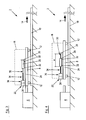
- a crash simulation device 2 is provided, which in Fig. 2 is shown schematically.
- the crash simulation device 2 has an acceleration or drive device 6.
- the crash simulation device 2 comprises a carriage 8, which is guided along a guide device, which is formed in the present example by guide rails 10, wherein the carriage 8 is supported in the illustrated embodiment via rollers 12 on the guide rails 10.
- the carriage 8 of the crash simulation device 2 can be accelerated in the direction 14 along the guide rails 10 with the aid of the accelerating device 6, it also being possible to speak in the direction 14 of the weft direction of the carriage 8.
- acceleration device 6 here is any drive in question, which is able to accelerate the carriage 8 in a way that an acceleration course of the carriage 8, which corresponds to the course of acceleration in a real collision of a motor vehicle with an obstacle substantially.
- a first additional mass 18 and a movable second additional mass 20 are arranged on the carriage 8 of the crash simulation device 2.
- the first additional mass 18 the sake of clarity in Fig. 3 is indicated only by dashed lines, it is attached to the carriage 8 so that it is firmly connected to the carriage 8 and thus can not be moved relative to the carriage 8.
- the first additional mass 18 has a weight that substantially corresponds to the weight of the vehicle or vehicle part used in the real-time test described later. It should be noted that the first additional mass can also be designed in several parts.
- the second additional mass 20 is formed as part of an additional device 22 for the acceleratable carriage 8 of the crash simulation device 2.
- the additional mass 20 in this case has a weight that substantially corresponds to the weight of the dummy used in the later-described real experiment.
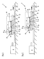
- This additional device 22 ( Fig. 3 ) initially has a base plate 24, by means of which the additional device 22 is detachably or detachably attached to the carriage 8. The base plate 24 is thus immovably fixed to the carriage 8. Alternatively, the additional device 22 could also be immovably fixed to the first additional mass 18 via the base plate 24.
- a first support portion 26 and one in the opposite Direction to the base plate 24 arranged second support portion 28 is provided, wherein the second support portion 28 is spaced in the opposite direction from the first support portion 26.
- a guide device 30 along which the aforementioned second additional mass 20 is guided and movable.
- the second additional mass 20 is guided on the one hand on the guide means 30 and supported on the other hand via rollers 32 on the upper side of the base plate 24.
- the second additional mass 20 is arranged movably relative to the carriage 8 on the carriage 8.
- a spring and / or damping device 34 is further provided, which is formed in the illustrated embodiment as a spring means.
- a damping device 36 is provided, wherein the operation of the spring and / or damping device 34 and the damping device 36 will be described in more detail below.
- method step 38 (FIG. Fig. 1 ) a preliminary test with the crash simulation device 2 and with reference to Fig. 3 described structure in which the carriage 8 is accelerated or shot by the accelerator 6 in the direction 14, wherein the individual phases of the preliminary test in the Fig. 4 to 7 are shown.
- the second additional mass 20 moves along the first path a along a second path b, as shown in FIG Fig. 5 is indicated.
- the second additional mass 20 is resiliently supported on the carriage 8 via the spring and / or damping device 34 and the second support section 28.
- the spring device 34 is elastically compressed by the moving second additional mass 20.
- the second additional mass 20 is damped by the damping device 36 on the second support portion 28 and thus supported on the carriage 8, so that the second additional mass 20 is first damped and then brought to a standstill relative to the carriage 8.
- the in Fig. 6 causes the compressed in the preceding phase spring means 34 that the additional mass 20 is again accelerated relative to the carriage 8 in the direction 14 until in a subsequent phase of the preliminary test, the in Fig. 7 is shown, the second additional mass 20 releases again from the spring means 34.
- the in Fig. 7 shown phase moves However, the second additional mass 20 turn freely along the first path a, but this time in the direction 14 relative to the carriage 8.
- braking devices are provided which control the movement slow or completely stop the second additional mass 20 in the direction 14 relative to the carriage 8.
- method step 40 determines the acceleration profile of the carriage 8 by means of suitable measuring instruments. Subsequently or at the same time, the detected acceleration profile is compared with a desired acceleration profile of the carriage 8. This is preferably done by specifying an upper limit acceleration course and a lower limit acceleration course, between which a corridor is formed, within which the desired acceleration course should lie. If the detected acceleration course deviates from the desired acceleration course, for example because it is arranged partially above the upper limit acceleration profile or partly below the lower limit acceleration profile, this is determined in method step 42 and a new preliminary test must be carried out, as described with reference to the arrow 44 in Fig. 1 is indicated.
- the settings of the components of the crash simulation device 2 that are decisive for the course of the acceleration of the carriage 8 are initially changed in order to achieve a modified acceleration profile in the second preliminary test, which more closely corresponds to the desired acceleration profile.
- the settings for the acceleration course of the carriage 8 relevant components of the crash simulation device 2 are such that the detected acceleration curve corresponds to the desired target acceleration curve of the carriage 8.
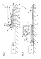
- the first additional mass 18 and the additional device 22, together with the second additional mass 20, are removed from the carriage 8, as is the case, for example Fig. 2 can be seen.
- a vehicle or vehicle part 48 is attached to the carriage 8, so that it is immovably connected to the carriage 8.
- a movable dummy 50 is arranged on the carriage 8 or the vehicle or vehicle part 48.
- the movable dummy 50 is preferably a person dummy, which is assigned a sensor system for detecting the forces, accelerations or / and speed acting on the dummy.
- the corresponding sensor may preferably be partially integrated in the dummy 50.
- the dummy 50 has a sensor system.
- the second additional mass 20 is arranged exchangeably on the additional device 22.
- an additional mass can be used in each case for the preliminary test, which essentially has the weight of the dummies 50 used in the later real test.
- the aforementioned additional device 22 may also be arranged only partially detachable on the carriage 8. However, it is preferred if the additional device 22 is designed to be completely removable from the carriage 8 in order to protect the individual components of the auxiliary device 22 from damage during the real tests.
Landscapes
- Physics & Mathematics (AREA)
- General Physics & Mathematics (AREA)
- Investigating Strength Of Materials By Application Of Mechanical Stress (AREA)
- Management, Administration, Business Operations System, And Electronic Commerce (AREA)
Claims (15)
- Procédé pour faire fonctionner une installation de simulation de collisions (2) pour des véhicules à moteur, comprenant les étapes de procédé suivantes :mise à disposition d'une installation de simulation de collisions (2) avec un chariot (8) pouvant être accéléré, fixation d'une première masse supplémentaire (18) sur le chariot (8), réalisation d'un essai préalable avec acquisition de l'évolution de l'accélération du chariot (8),comparaison de l'évolution de l'accélération acquise à une consigne d'évolution de l'accélération du chariot (8),réalisation d'un autre essai préalable avec un réglage modifié des composants de l'installation de simulation de collisions (2) déterminants pour l'évolution de l'accélération du chariot (8) si l'évolution de l'accélération acquise s'écarte de la consigne d'évolution de l'accélération,retrait de la première masse supplémentaire (18) du chariot (8) si l'évolution de l'accélération acquise correspond à la consigne d'évolution de l'accélération, fixation d'un véhicule ou d'une partie de véhicule (48) sur le chariot (8), disposition d'au moins un mannequin (50) mobile sur le chariot (8) et/ou sur le véhicule ou la partie de véhicule (48) etréalisation d'au moins un essai réel avec les réglages des composants de l'installation de simulation de collisions (2) déterminants pour l'évolution de l'accélération du chariot (8) effectués lors de l'essai préalable ou des essais préalables,caractérisé en ce qu'au moins une deuxième masse supplémentaire (20) est disposée sur le chariot (8) avant la réalisation de l'essai préalable ou des essais préalables.
- Procédé selon la revendication 1, caractérisé en ce que la deuxième masse supplémentaire (20) est enlevée du chariot (8) avant la réalisation de l'essai réel.
- Procédé selon l'une des revendications 1 ou 2, caractérisé en ce que la deuxième masse supplémentaire (20) est disposée indirectement sur le chariot (8) en cela que la deuxième masse supplémentaire (20) est disposée ou présente sur la première masse supplémentaire (18).
- Procédé selon la revendication 3, caractérisé en ce que la deuxième masse supplémentaire (20) est disposée sur le chariot (8) en même temps que la première masse supplémentaire (18) et/ou enlevée du chariot (8) avec celle-ci.
- Procédé selon l'une des revendications précédentes, caractérisé en ce que la deuxième masse supplémentaire (20) est disposée sur le chariot (8) ou sur la première masse supplémentaire (18) de telle manière que la deuxième masse supplémentaire (20) est tout d'abord librement mobile le long d'une première distance de trajet (a) puis mobile le long d'une deuxième distance de trajet (b) en s'appuyant de manière suspendue et/ou amortie, de préférence suspendue, sur le chariot (8) ou sur la première masse supplémentaire (18).
- Procédé selon la revendication 5, caractérisé en ce que la deuxième masse supplémentaire (20) est disposée sur le chariot (8) ou sur la première masse supplémentaire (18) de telle manière que la deuxième masse supplémentaire (20) s'appuie de façon amortie sur le chariot (8) ou sur la première masse supplémentaire (18) après la deuxième distance de trajet (b).
- Procédé selon l'une des revendications précédentes, caractérisé en ce qu'un dispositif supplémentaire (22) est fixé ou se fixe avant l'essai préalable sur le chariot (8) ou la première masse supplémentaire (18), lequel comporte la deuxième masse supplémentaire (20), un dispositif de guidage (30) pour le guidage de la deuxième masse supplémentaire (20) et un dispositif de suspension et/ou d'amortissement (34), ce dispositif supplémentaire (22) étant entièrement ou partiellement enlevé du chariot (8) avant la réalisation de l'essai réel.
- Procédé selon l'une des revendications précédentes, caractérisé en ce que l'on utilise une deuxième masse supplémentaire (20) dont le poids correspond sensiblement au poids du mannequin (50) dans l'essai réel, et/ou on utilise une première masse supplémentaire (18) dont le poids correspond sensiblement au poids du véhicule ou de la partie de véhicule (48) dans l'essai réel.
- Procédé selon l'une des revendications précédentes, caractérisé en ce que l'on utilise dans l'essai réel un mannequin (50) associé à des capteurs pour détecter les forces, les accélérations et/ou les vitesses agissant sur le mannequin (50), le mannequin (50) étant de préférence un mannequin à forme humaine et aucun capteur n'étant en particulier associé à la deuxième masse supplémentaire (20).
- Dispositif supplémentaire (22) pour un chariot (8) pouvant être accéléré dans une installation de simulation de collisions (2), qui peut être utilisé dans les essais préalables du procédé selon l'une des revendications 1 à 9, caractérisé en ce que le dispositif supplémentaire (22) pouvant être fixé à un chariot (8) d'une installation de simulation de collisions (2) présente au moins une masse supplémentaire (20) mobile le long d'un dispositif de guidage (30).
- Dispositif supplémentaire (22) selon la revendication 10, caractérisé en ce que la masse supplémentaire (20) est guidée de façon librement mobile par le dispositif de guidage (30) le long d'une première distance de trajet (a).
- Dispositif supplémentaire (22) selon la revendication 11, caractérisé en ce qu'il est prévu une section de support (28) qui peut être fixée directement ou indirectement sur le chariot (8) de l'installation de simulation de collisions (2) et un dispositif de suspension et/ou d'amortissement (34), de préférence un dispositif de suspension (34) agissant entre la section de support (28) et la masse supplémentaire (20), de sorte que la masse supplémentaire (20) est guidée après la première distance de trajet (a) par le dispositif de guidage (30) en étant soutenue de façon suspendue et/ou amortie, de préférence de façon suspendue, sur la section de support (28) le long d'une deuxième distance de trajet (b).
- Dispositif supplémentaire (22) selon la revendication 12, caractérisé en ce qu'il est prévu un dispositif d'amortissement (36) qui agit entre la section de support (28) et la masse supplémentaire (20) de telle manière que la masse supplémentaire (20) s'appuie de façon amortie sur la section de support (28) après la deuxième distance de trajet (b).
- Dispositif supplémentaire (22) selon l'une des revendications 10 à 13, caractérisé en ce que la masse supplémentaire (20) est disposée sur le dispositif supplémentaire (22) de façon à pouvoir être échangée.
- Installation de simulation de collisions (2) pour un véhicule à moteur avec un chariot (8) pouvant être accéléré, caractérisée en ce qu'est fixé sur le chariot (8) un dispositif supplémentaire (22) selon l'une des revendications 10 à 14, le dispositif supplémentaire (22) pouvant de préférence être entièrement ou partiellement enlevé du chariot (8).
Applications Claiming Priority (2)
| Application Number | Priority Date | Filing Date | Title |
|---|---|---|---|
| DE102009038455A DE102009038455A1 (de) | 2009-08-21 | 2009-08-21 | Verfahren zum Betrieb einer Crashsimulationseinrichtung, Zusatzvorrichtung für eine Crashsimulationseinrichtung und Crashsimulationseinrichtung mit einer solchen Zusatzvorrichtung |
| PCT/EP2010/004031 WO2011020524A1 (fr) | 2009-08-21 | 2010-07-03 | Procédé permettant de faire fonctionner un dispositif de simulation de collision, équipement additionnel destiné à un dispositif de simulation de collision, et dispositif de simulation de collision comportant ledit équipement additionnel |
Publications (2)
| Publication Number | Publication Date |
|---|---|
| EP2467693A1 EP2467693A1 (fr) | 2012-06-27 |
| EP2467693B1 true EP2467693B1 (fr) | 2013-06-05 |
Family
ID=42829575
Family Applications (1)
| Application Number | Title | Priority Date | Filing Date |
|---|---|---|---|
| EP10740149.9A Not-in-force EP2467693B1 (fr) | 2009-08-21 | 2010-07-03 | Procédé permettant de faire fonctionner un dispositif de simulation de collision, équipement additionnel destiné à un dispositif de simulation de collision, et dispositif de simulation de collision comportant ledit équipement additionnel |
Country Status (6)
| Country | Link |
|---|---|
| US (1) | US20120204630A1 (fr) |
| EP (1) | EP2467693B1 (fr) |
| KR (1) | KR20120090974A (fr) |
| CN (1) | CN102472688B (fr) |
| DE (1) | DE102009038455A1 (fr) |
| WO (1) | WO2011020524A1 (fr) |
Families Citing this family (14)
| Publication number | Priority date | Publication date | Assignee | Title |
|---|---|---|---|---|
| DE102011085791B4 (de) * | 2011-11-04 | 2015-04-02 | Illinois Tool Works Inc. | Prüfeinrichtung für Crash-Simulationsversuche |
| DE102012025714B3 (de) | 2012-04-24 | 2018-05-30 | Illinois Tool Works, Inc. | Prüfeinrichtung zur Kraftfahrzeug-Crashsimulation sowie Verfahren zum Betrieb einer Prüfeinrichtung |
| DE102012206744B4 (de) * | 2012-04-24 | 2014-10-09 | Illinois Tool Works, Inc. | Prüfeinrichtung zur Kraftfahrzeug-Crashsimulation sowie Verfahren zum Betrieb einer Prüfeinrichtung |
| CN103325293B (zh) * | 2013-05-29 | 2016-01-20 | 哈尔滨工业大学 | 一种利用飞轮储能的应用到物体碰撞时等效质量模拟装置 |
| DE102013013980B4 (de) | 2013-08-23 | 2018-03-29 | Iav Gmbh Ingenieurgesellschaft Auto Und Verkehr | Verfahren zum Betreiben einer Crashsimulationsanlage |
| US9976935B2 (en) * | 2016-06-07 | 2018-05-22 | Ford Global Technologies, Llc | Method and system for evaluating structural vehicle component performance |
| JP6702831B2 (ja) * | 2016-09-13 | 2020-06-03 | 三菱重工機械システム株式会社 | 自動車衝突模擬試験装置 |
| CN106441935A (zh) * | 2016-09-29 | 2017-02-22 | 百度在线网络技术(北京)有限公司 | 用于车辆碰撞测试的假人的移动设备和假人测试设备 |
| CN106769087B (zh) * | 2016-12-15 | 2019-02-15 | 浙江吉利汽车研究院有限公司 | 一种碰撞试验车辆调正装置 |
| CN110083949B (zh) * | 2019-04-30 | 2023-04-07 | 重庆长安汽车股份有限公司 | 一种前置传感器信号复现方法及系统 |
| CN111761559B (zh) * | 2020-06-24 | 2022-08-26 | 摩登汽车有限公司 | 集成可收纳式配重袋的工具箱及其使用方法 |
| CN113916559B (zh) * | 2021-12-09 | 2022-03-15 | 中国汽车技术研究中心有限公司 | 碰撞假人冲击响应性能限值的构建方法及电子设备 |
| WO2024085869A1 (fr) * | 2022-10-19 | 2024-04-25 | Seattle Safety, Llc | Fixation sous vide de feuille de couverture de panneau |
| CN115575141B (zh) * | 2022-12-09 | 2023-06-06 | 中国汽车技术研究中心有限公司 | 汽车碰撞假人胸部标定方法和设备 |
Family Cites Families (17)
| Publication number | Priority date | Publication date | Assignee | Title |
|---|---|---|---|---|
| US3430481A (en) * | 1966-11-16 | 1969-03-04 | Bliss Co | Dynamic test machine |
| US5485758A (en) * | 1993-12-27 | 1996-01-23 | Trw Vehicle Safety Systems Inc. | Method and apparatus for simulating vehicle side impacts |
| US5483845A (en) * | 1994-09-12 | 1996-01-16 | Morton International, Inc. | Apparatus and method for side impact testing |
| US5623094A (en) * | 1996-01-17 | 1997-04-22 | Mga Research Corporation | Sled testing system |
| US5783739A (en) * | 1996-08-20 | 1998-07-21 | Mga Research Corporation | Sled docking system |
| US5872321A (en) * | 1997-12-08 | 1999-02-16 | The United States Of America As Represented By The Secretary Of The Navy | Side impact injury test apparatus |
| DE29721927U1 (de) * | 1997-12-11 | 1998-05-14 | Trw Occupant Restraint Systems Gmbh, 73551 Alfdorf | Vorrichtung zum Testen von Fahrzeuginsassen-Rückhaltesystemen für einen Seitenaufprall |
| DE29910483U1 (de) * | 1999-06-15 | 1999-12-02 | TRW Occupant Restraint Systems GmbH & Co. KG, 73553 Alfdorf | Prüfstand für Fahrzeugteile |
| CN1280620C (zh) * | 2001-07-06 | 2006-10-18 | 本田技研工业株式会社 | 车辆碰撞试验装置 |
| FR2832217B1 (fr) * | 2001-11-13 | 2004-10-01 | Alstom | Dispositif pour la realisation d'essais mecaniques sur des structures |
| DE10222086A1 (de) * | 2002-05-17 | 2003-11-27 | Trw Repa Gmbh | Anlage und Verfahren zum Simulieren eines Fahrzeugunfalls |
| WO2005010478A1 (fr) * | 2003-07-23 | 2005-02-03 | Mts Systems Corporation | Element de force pour simulateur de collision de vehicule |
| AT8091U1 (de) * | 2004-06-09 | 2006-01-15 | Magna Steyr Fahrzeugtechnik Ag | Vorrichtung zur simulation einer seitenkollision eines kraftfahrzeuges |
| US7380436B2 (en) * | 2005-03-17 | 2008-06-03 | Ford Global Technologies, Llc | Rollover component test fixture and methodology |
| DE102005042260B4 (de) * | 2005-09-02 | 2009-12-03 | Iav Gmbh Ingenieurgesellschaft Auto Und Verkehr | Anlage zur Simulation eines Seitencrashs mit einer Schlittenanlage |
| US7610821B2 (en) * | 2006-07-19 | 2009-11-03 | Toyoda Gosei Co., Ltd. | Side impact dynamic intrusion simulator |
| DE102008011356A1 (de) * | 2008-02-27 | 2009-09-03 | Fachhochschule Kaiserslautern | Anordnung zur Simulation von Aufprallunfällen |
-
2009
- 2009-08-21 DE DE102009038455A patent/DE102009038455A1/de not_active Withdrawn
-
2010
- 2010-07-03 EP EP10740149.9A patent/EP2467693B1/fr not_active Not-in-force
- 2010-07-03 CN CN201080036713.3A patent/CN102472688B/zh not_active Expired - Fee Related
- 2010-07-03 WO PCT/EP2010/004031 patent/WO2011020524A1/fr not_active Ceased
- 2010-07-03 US US13/390,371 patent/US20120204630A1/en not_active Abandoned
- 2010-07-03 KR KR1020127006803A patent/KR20120090974A/ko not_active Withdrawn
Also Published As
| Publication number | Publication date |
|---|---|
| CN102472688B (zh) | 2015-01-14 |
| EP2467693A1 (fr) | 2012-06-27 |
| CN102472688A (zh) | 2012-05-23 |
| WO2011020524A1 (fr) | 2011-02-24 |
| DE102009038455A1 (de) | 2011-02-24 |
| KR20120090974A (ko) | 2012-08-17 |
| US20120204630A1 (en) | 2012-08-16 |
Similar Documents
| Publication | Publication Date | Title |
|---|---|---|
| EP2467693B1 (fr) | Procédé permettant de faire fonctionner un dispositif de simulation de collision, équipement additionnel destiné à un dispositif de simulation de collision, et dispositif de simulation de collision comportant ledit équipement additionnel | |
| EP1763662B1 (fr) | Dispositif de simulation d'une collision latérale d'un véhicule | |
| DE102015013401B3 (de) | Vorrichtung und Verfahren zur Kalibrierung und/oder Justage von Messeinrichtungen für dynamische Kräfte | |
| WO2009103384A1 (fr) | Dispositif pour déplacer des maquettes | |
| DE102008053992B3 (de) | Prüfstand für Fahrzeugkomponenten | |
| EP3298377B1 (fr) | Dispositif de pendule de test et procédé de fonctionnement d'un dispositif de pendule de test | |
| DE102013217792B3 (de) | Verfahren zum Testen eines Bauteils eines Fahrzeugs und Anlage für Fahrzeugbauteil-Kollisionsversuche | |
| WO2021239505A1 (fr) | Banc d'essai et installation d'essai pour tester un système de ceinture de sécurité et/ou pour tester des constituants d'un système de ceinture de sécurité, et procédé de fonctionnement d'un banc d'essai | |
| DE102019129721B3 (de) | Bremsvorrichtungssystem, Prüfpendelanordnung zur Durchführung von Halszertifizierungen sowie Verfahren zum Betrieb einer Prüfpendelanordnung | |
| DE102011103431B4 (de) | Verfahren zur Durchführung von Crash-Schlittenversuchen und Crash-Simulationsanlage | |
| EP1657538B1 (fr) | Dispositif pour la simulation de collision d'un véhicule | |
| DE102011089432A1 (de) | Vorrichtung mit einstellbarer Steifigkeit zum Aufnehmen einer Aufprallenergie | |
| DE102005042260B4 (de) | Anlage zur Simulation eines Seitencrashs mit einer Schlittenanlage | |
| EP1750112B1 (fr) | Procédé d'application de forces supplémentaires lors de l'exécution d'essais de collision et montage d'essai correspondant | |
| DE19739141C1 (de) | Einrichtung zum Nachstellen der dynamischen Intrusion von Fahrzeugteilen eines Kraftfahrzeuges bei einem Aufprall | |
| DE102007056572A1 (de) | Verfahren zur Durchführung von Crash-Schlitten-Versuchen, sowie Vorrichtung zum Durchführen des Verfahrens | |
| DE102004029426A1 (de) | Vorrichtung und Verfahren zur Simulierung einer Kollision, insbesondere eines Kraftfahrzeugs mit einem Gegenstand | |
| DE102005040134B3 (de) | Prüfkörperfangvorrichtung | |
| DE102010002667A1 (de) | Testanordnung zum Testen einer Kraftfahrzeugbaugruppe | |
| DE102017209837A1 (de) | Crashanlage mit entkoppelter Crashmesswand | |
| DE102007056573B4 (de) | Verfahren zur Durchführung von Crash-Schlitten-Versuchen mit vor dem Aufprall auftretender Gierbewegung | |
| DE10220613B4 (de) | Verfahren und Vorrichtung zur Durchführung von sogenannten Crashtests | |
| DE102017219083B4 (de) | Kollisionstestanordnung und Verfahren zum Durchführen eines Kollisionstests | |
| DE202015009480U1 (de) | Prüfpendelanordnung | |
| DE102013013980B4 (de) | Verfahren zum Betreiben einer Crashsimulationsanlage |
Legal Events
| Date | Code | Title | Description |
|---|---|---|---|
| PUAI | Public reference made under article 153(3) epc to a published international application that has entered the european phase |
Free format text: ORIGINAL CODE: 0009012 |
|
| 17P | Request for examination filed |
Effective date: 20120321 |
|
| AK | Designated contracting states |
Kind code of ref document: A1 Designated state(s): AL AT BE BG CH CY CZ DE DK EE ES FI FR GB GR HR HU IE IS IT LI LT LU LV MC MK MT NL NO PL PT RO SE SI SK SM TR |
|
| DAX | Request for extension of the european patent (deleted) | ||
| GRAP | Despatch of communication of intention to grant a patent |
Free format text: ORIGINAL CODE: EPIDOSNIGR1 |
|
| GRAS | Grant fee paid |
Free format text: ORIGINAL CODE: EPIDOSNIGR3 |
|
| GRAA | (expected) grant |
Free format text: ORIGINAL CODE: 0009210 |
|
| AK | Designated contracting states |
Kind code of ref document: B1 Designated state(s): AL AT BE BG CH CY CZ DE DK EE ES FI FR GB GR HR HU IE IS IT LI LT LU LV MC MK MT NL NO PL PT RO SE SI SK SM TR |
|
| REG | Reference to a national code |
Ref country code: GB Ref legal event code: FG4D Free format text: NOT ENGLISH |
|
| REG | Reference to a national code |
Ref country code: CH Ref legal event code: EP |
|
| REG | Reference to a national code |
Ref country code: AT Ref legal event code: REF Ref document number: 615934 Country of ref document: AT Kind code of ref document: T Effective date: 20130615 |
|
| REG | Reference to a national code |
Ref country code: IE Ref legal event code: FG4D Free format text: LANGUAGE OF EP DOCUMENT: GERMAN |
|
| REG | Reference to a national code |
Ref country code: DE Ref legal event code: R096 Ref document number: 502010003591 Country of ref document: DE Effective date: 20130725 |
|
| PG25 | Lapsed in a contracting state [announced via postgrant information from national office to epo] |
Ref country code: ES Free format text: LAPSE BECAUSE OF FAILURE TO SUBMIT A TRANSLATION OF THE DESCRIPTION OR TO PAY THE FEE WITHIN THE PRESCRIBED TIME-LIMIT Effective date: 20130916 Ref country code: SI Free format text: LAPSE BECAUSE OF FAILURE TO SUBMIT A TRANSLATION OF THE DESCRIPTION OR TO PAY THE FEE WITHIN THE PRESCRIBED TIME-LIMIT Effective date: 20130605 Ref country code: NO Free format text: LAPSE BECAUSE OF FAILURE TO SUBMIT A TRANSLATION OF THE DESCRIPTION OR TO PAY THE FEE WITHIN THE PRESCRIBED TIME-LIMIT Effective date: 20130905 Ref country code: SE Free format text: LAPSE BECAUSE OF FAILURE TO SUBMIT A TRANSLATION OF THE DESCRIPTION OR TO PAY THE FEE WITHIN THE PRESCRIBED TIME-LIMIT Effective date: 20130605 Ref country code: LT Free format text: LAPSE BECAUSE OF FAILURE TO SUBMIT A TRANSLATION OF THE DESCRIPTION OR TO PAY THE FEE WITHIN THE PRESCRIBED TIME-LIMIT Effective date: 20130605 Ref country code: FI Free format text: LAPSE BECAUSE OF FAILURE TO SUBMIT A TRANSLATION OF THE DESCRIPTION OR TO PAY THE FEE WITHIN THE PRESCRIBED TIME-LIMIT Effective date: 20130605 Ref country code: GR Free format text: LAPSE BECAUSE OF FAILURE TO SUBMIT A TRANSLATION OF THE DESCRIPTION OR TO PAY THE FEE WITHIN THE PRESCRIBED TIME-LIMIT Effective date: 20130906 |
|
| REG | Reference to a national code |
Ref country code: NL Ref legal event code: VDEP Effective date: 20130605 |
|
| REG | Reference to a national code |
Ref country code: LT Ref legal event code: MG4D |
|
| PG25 | Lapsed in a contracting state [announced via postgrant information from national office to epo] |
Ref country code: BG Free format text: LAPSE BECAUSE OF FAILURE TO SUBMIT A TRANSLATION OF THE DESCRIPTION OR TO PAY THE FEE WITHIN THE PRESCRIBED TIME-LIMIT Effective date: 20130905 Ref country code: HR Free format text: LAPSE BECAUSE OF FAILURE TO SUBMIT A TRANSLATION OF THE DESCRIPTION OR TO PAY THE FEE WITHIN THE PRESCRIBED TIME-LIMIT Effective date: 20130605 |
|
| PG25 | Lapsed in a contracting state [announced via postgrant information from national office to epo] |
Ref country code: LV Free format text: LAPSE BECAUSE OF FAILURE TO SUBMIT A TRANSLATION OF THE DESCRIPTION OR TO PAY THE FEE WITHIN THE PRESCRIBED TIME-LIMIT Effective date: 20130605 |
|
| BERE | Be: lapsed |
Owner name: GM GLOBAL TECHNOLOGY OPERATIONS LLC Effective date: 20130731 |
|
| PG25 | Lapsed in a contracting state [announced via postgrant information from national office to epo] |
Ref country code: EE Free format text: LAPSE BECAUSE OF FAILURE TO SUBMIT A TRANSLATION OF THE DESCRIPTION OR TO PAY THE FEE WITHIN THE PRESCRIBED TIME-LIMIT Effective date: 20130605 Ref country code: SK Free format text: LAPSE BECAUSE OF FAILURE TO SUBMIT A TRANSLATION OF THE DESCRIPTION OR TO PAY THE FEE WITHIN THE PRESCRIBED TIME-LIMIT Effective date: 20130605 Ref country code: IS Free format text: LAPSE BECAUSE OF FAILURE TO SUBMIT A TRANSLATION OF THE DESCRIPTION OR TO PAY THE FEE WITHIN THE PRESCRIBED TIME-LIMIT Effective date: 20131005 Ref country code: PT Free format text: LAPSE BECAUSE OF FAILURE TO SUBMIT A TRANSLATION OF THE DESCRIPTION OR TO PAY THE FEE WITHIN THE PRESCRIBED TIME-LIMIT Effective date: 20131007 Ref country code: CZ Free format text: LAPSE BECAUSE OF FAILURE TO SUBMIT A TRANSLATION OF THE DESCRIPTION OR TO PAY THE FEE WITHIN THE PRESCRIBED TIME-LIMIT Effective date: 20130605 |
|
| PG25 | Lapsed in a contracting state [announced via postgrant information from national office to epo] |
Ref country code: PL Free format text: LAPSE BECAUSE OF FAILURE TO SUBMIT A TRANSLATION OF THE DESCRIPTION OR TO PAY THE FEE WITHIN THE PRESCRIBED TIME-LIMIT Effective date: 20130605 Ref country code: NL Free format text: LAPSE BECAUSE OF FAILURE TO SUBMIT A TRANSLATION OF THE DESCRIPTION OR TO PAY THE FEE WITHIN THE PRESCRIBED TIME-LIMIT Effective date: 20130605 Ref country code: RO Free format text: LAPSE BECAUSE OF FAILURE TO SUBMIT A TRANSLATION OF THE DESCRIPTION OR TO PAY THE FEE WITHIN THE PRESCRIBED TIME-LIMIT Effective date: 20130605 |
|
| PG25 | Lapsed in a contracting state [announced via postgrant information from national office to epo] |
Ref country code: MC Free format text: LAPSE BECAUSE OF FAILURE TO SUBMIT A TRANSLATION OF THE DESCRIPTION OR TO PAY THE FEE WITHIN THE PRESCRIBED TIME-LIMIT Effective date: 20130605 |
|
| PLBE | No opposition filed within time limit |
Free format text: ORIGINAL CODE: 0009261 |
|
| STAA | Information on the status of an ep patent application or granted ep patent |
Free format text: STATUS: NO OPPOSITION FILED WITHIN TIME LIMIT |
|
| REG | Reference to a national code |
Ref country code: IE Ref legal event code: MM4A |
|
| PG25 | Lapsed in a contracting state [announced via postgrant information from national office to epo] |
Ref country code: DK Free format text: LAPSE BECAUSE OF FAILURE TO SUBMIT A TRANSLATION OF THE DESCRIPTION OR TO PAY THE FEE WITHIN THE PRESCRIBED TIME-LIMIT Effective date: 20130605 Ref country code: BE Free format text: LAPSE BECAUSE OF NON-PAYMENT OF DUE FEES Effective date: 20130731 |
|
| 26N | No opposition filed |
Effective date: 20140306 |
|
| PG25 | Lapsed in a contracting state [announced via postgrant information from national office to epo] |
Ref country code: IT Free format text: LAPSE BECAUSE OF FAILURE TO SUBMIT A TRANSLATION OF THE DESCRIPTION OR TO PAY THE FEE WITHIN THE PRESCRIBED TIME-LIMIT Effective date: 20130605 |
|
| REG | Reference to a national code |
Ref country code: DE Ref legal event code: R097 Ref document number: 502010003591 Country of ref document: DE Effective date: 20140306 |
|
| PG25 | Lapsed in a contracting state [announced via postgrant information from national office to epo] |
Ref country code: IE Free format text: LAPSE BECAUSE OF NON-PAYMENT OF DUE FEES Effective date: 20130703 |
|
| REG | Reference to a national code |
Ref country code: CH Ref legal event code: PL |
|
| PG25 | Lapsed in a contracting state [announced via postgrant information from national office to epo] |
Ref country code: LI Free format text: LAPSE BECAUSE OF NON-PAYMENT OF DUE FEES Effective date: 20140731 Ref country code: CH Free format text: LAPSE BECAUSE OF NON-PAYMENT OF DUE FEES Effective date: 20140731 |
|
| PG25 | Lapsed in a contracting state [announced via postgrant information from national office to epo] |
Ref country code: SM Free format text: LAPSE BECAUSE OF FAILURE TO SUBMIT A TRANSLATION OF THE DESCRIPTION OR TO PAY THE FEE WITHIN THE PRESCRIBED TIME-LIMIT Effective date: 20130605 |
|
| PG25 | Lapsed in a contracting state [announced via postgrant information from national office to epo] |
Ref country code: TR Free format text: LAPSE BECAUSE OF FAILURE TO SUBMIT A TRANSLATION OF THE DESCRIPTION OR TO PAY THE FEE WITHIN THE PRESCRIBED TIME-LIMIT Effective date: 20130605 Ref country code: MT Free format text: LAPSE BECAUSE OF FAILURE TO SUBMIT A TRANSLATION OF THE DESCRIPTION OR TO PAY THE FEE WITHIN THE PRESCRIBED TIME-LIMIT Effective date: 20130605 Ref country code: CY Free format text: LAPSE BECAUSE OF FAILURE TO SUBMIT A TRANSLATION OF THE DESCRIPTION OR TO PAY THE FEE WITHIN THE PRESCRIBED TIME-LIMIT Effective date: 20130605 |
|
| PG25 | Lapsed in a contracting state [announced via postgrant information from national office to epo] |
Ref country code: HU Free format text: LAPSE BECAUSE OF FAILURE TO SUBMIT A TRANSLATION OF THE DESCRIPTION OR TO PAY THE FEE WITHIN THE PRESCRIBED TIME-LIMIT; INVALID AB INITIO Effective date: 20100703 Ref country code: MK Free format text: LAPSE BECAUSE OF FAILURE TO SUBMIT A TRANSLATION OF THE DESCRIPTION OR TO PAY THE FEE WITHIN THE PRESCRIBED TIME-LIMIT Effective date: 20130605 Ref country code: LU Free format text: LAPSE BECAUSE OF NON-PAYMENT OF DUE FEES Effective date: 20130703 |
|
| REG | Reference to a national code |
Ref country code: FR Ref legal event code: PLFP Year of fee payment: 7 |
|
| PGFP | Annual fee paid to national office [announced via postgrant information from national office to epo] |
Ref country code: GB Payment date: 20160629 Year of fee payment: 7 |
|
| PGFP | Annual fee paid to national office [announced via postgrant information from national office to epo] |
Ref country code: FR Payment date: 20160613 Year of fee payment: 7 |
|
| REG | Reference to a national code |
Ref country code: AT Ref legal event code: MM01 Ref document number: 615934 Country of ref document: AT Kind code of ref document: T Effective date: 20150703 |
|
| PG25 | Lapsed in a contracting state [announced via postgrant information from national office to epo] |
Ref country code: AT Free format text: LAPSE BECAUSE OF NON-PAYMENT OF DUE FEES Effective date: 20150703 |
|
| GBPC | Gb: european patent ceased through non-payment of renewal fee |
Effective date: 20170703 |
|
| REG | Reference to a national code |
Ref country code: FR Ref legal event code: ST Effective date: 20180330 |
|
| PG25 | Lapsed in a contracting state [announced via postgrant information from national office to epo] |
Ref country code: GB Free format text: LAPSE BECAUSE OF NON-PAYMENT OF DUE FEES Effective date: 20170703 |
|
| PG25 | Lapsed in a contracting state [announced via postgrant information from national office to epo] |
Ref country code: FR Free format text: LAPSE BECAUSE OF NON-PAYMENT OF DUE FEES Effective date: 20170731 |
|
| PG25 | Lapsed in a contracting state [announced via postgrant information from national office to epo] |
Ref country code: AL Free format text: LAPSE BECAUSE OF FAILURE TO SUBMIT A TRANSLATION OF THE DESCRIPTION OR TO PAY THE FEE WITHIN THE PRESCRIBED TIME-LIMIT Effective date: 20130605 |
|
| PGFP | Annual fee paid to national office [announced via postgrant information from national office to epo] |
Ref country code: DE Payment date: 20180619 Year of fee payment: 9 |
|
| REG | Reference to a national code |
Ref country code: DE Ref legal event code: R119 Ref document number: 502010003591 Country of ref document: DE |
|
| PG25 | Lapsed in a contracting state [announced via postgrant information from national office to epo] |
Ref country code: DE Free format text: LAPSE BECAUSE OF NON-PAYMENT OF DUE FEES Effective date: 20200201 |