EP2468190A1 - Ultraschall-Sonde, Ultraschall-Monitoring-System sowie deren Verwendung - Google Patents
Ultraschall-Sonde, Ultraschall-Monitoring-System sowie deren Verwendung Download PDFInfo
- Publication number
- EP2468190A1 EP2468190A1 EP10016067A EP10016067A EP2468190A1 EP 2468190 A1 EP2468190 A1 EP 2468190A1 EP 10016067 A EP10016067 A EP 10016067A EP 10016067 A EP10016067 A EP 10016067A EP 2468190 A1 EP2468190 A1 EP 2468190A1
- Authority
- EP
- European Patent Office
- Prior art keywords
- housing
- ultrasonic
- ultrasonic probe
- ultrasound
- probe according
- Prior art date
- Legal status (The legal status is an assumption and is not a legal conclusion. Google has not performed a legal analysis and makes no representation as to the accuracy of the status listed.)
- Withdrawn
Links
- 239000000523 sample Substances 0.000 title claims abstract description 78
- 238000002604 ultrasonography Methods 0.000 title claims abstract description 35
- 238000012544 monitoring process Methods 0.000 title claims abstract description 18
- PEDCQBHIVMGVHV-UHFFFAOYSA-N Glycerine Chemical compound OCC(O)CO PEDCQBHIVMGVHV-UHFFFAOYSA-N 0.000 claims abstract description 8
- 239000007788 liquid Substances 0.000 claims abstract description 5
- XLYOFNOQVPJJNP-UHFFFAOYSA-N water Substances O XLYOFNOQVPJJNP-UHFFFAOYSA-N 0.000 claims abstract description 4
- 239000013078 crystal Substances 0.000 claims description 7
- 239000012528 membrane Substances 0.000 claims description 4
- 208000006011 Stroke Diseases 0.000 claims description 3
- 238000000502 dialysis Methods 0.000 claims description 3
- 150000001298 alcohols Chemical class 0.000 claims description 2
- 210000001367 artery Anatomy 0.000 claims description 2
- 239000000560 biocompatible material Substances 0.000 claims description 2
- 210000004556 brain Anatomy 0.000 claims description 2
- 239000011521 glass Substances 0.000 claims description 2
- 239000003921 oil Substances 0.000 claims description 2
- 239000000725 suspension Substances 0.000 claims description 2
- LFQSCWFLJHTTHZ-UHFFFAOYSA-N Ethanol Chemical compound CCO LFQSCWFLJHTTHZ-UHFFFAOYSA-N 0.000 abstract 1
- 230000008878 coupling Effects 0.000 description 2
- 238000010168 coupling process Methods 0.000 description 2
- 238000005859 coupling reaction Methods 0.000 description 2
- 230000036642 wellbeing Effects 0.000 description 2
- 230000005540 biological transmission Effects 0.000 description 1
- 230000017531 blood circulation Effects 0.000 description 1
- 230000002490 cerebral effect Effects 0.000 description 1
- 230000001419 dependent effect Effects 0.000 description 1
- 238000011161 development Methods 0.000 description 1
- 230000018109 developmental process Effects 0.000 description 1
- 239000003814 drug Substances 0.000 description 1
- 210000003743 erythrocyte Anatomy 0.000 description 1
- 230000005284 excitation Effects 0.000 description 1
- 235000011187 glycerol Nutrition 0.000 description 1
- 230000004886 head movement Effects 0.000 description 1
- 230000036541 health Effects 0.000 description 1
- 238000011835 investigation Methods 0.000 description 1
- 238000005457 optimization Methods 0.000 description 1
- 230000005855 radiation Effects 0.000 description 1
- 238000010845 search algorithm Methods 0.000 description 1
- 238000000527 sonication Methods 0.000 description 1
- 230000007704 transition Effects 0.000 description 1
- 230000002792 vascular Effects 0.000 description 1
Images



Classifications
-
- A—HUMAN NECESSITIES
- A61—MEDICAL OR VETERINARY SCIENCE; HYGIENE
- A61B—DIAGNOSIS; SURGERY; IDENTIFICATION
- A61B8/00—Diagnosis using ultrasonic, sonic or infrasonic waves
- A61B8/44—Constructional features of the ultrasonic, sonic or infrasonic diagnostic device
- A61B8/4444—Constructional features of the ultrasonic, sonic or infrasonic diagnostic device related to the probe
- A61B8/4461—Features of the scanning mechanism, e.g. for moving the transducer within the housing of the probe
-
- A—HUMAN NECESSITIES
- A61—MEDICAL OR VETERINARY SCIENCE; HYGIENE
- A61B—DIAGNOSIS; SURGERY; IDENTIFICATION
- A61B8/00—Diagnosis using ultrasonic, sonic or infrasonic waves
- A61B8/42—Details of probe positioning or probe attachment to the patient
- A61B8/4272—Details of probe positioning or probe attachment to the patient involving the acoustic interface between the transducer and the tissue
- A61B8/4281—Details of probe positioning or probe attachment to the patient involving the acoustic interface between the transducer and the tissue characterised by sound-transmitting media or devices for coupling the transducer to the tissue
-
- G—PHYSICS
- G01—MEASURING; TESTING
- G01S—RADIO DIRECTION-FINDING; RADIO NAVIGATION; DETERMINING DISTANCE OR VELOCITY BY USE OF RADIO WAVES; LOCATING OR PRESENCE-DETECTING BY USE OF THE REFLECTION OR RERADIATION OF RADIO WAVES; ANALOGOUS ARRANGEMENTS USING OTHER WAVES
- G01S15/00—Systems using the reflection or reradiation of acoustic waves, e.g. sonar systems
- G01S15/88—Sonar systems specially adapted for specific applications
- G01S15/89—Sonar systems specially adapted for specific applications for mapping or imaging
- G01S15/8906—Short-range imaging systems; Acoustic microscope systems using pulse-echo techniques
- G01S15/8934—Short-range imaging systems; Acoustic microscope systems using pulse-echo techniques using a dynamic transducer configuration
- G01S15/8936—Short-range imaging systems; Acoustic microscope systems using pulse-echo techniques using a dynamic transducer configuration using transducers mounted for mechanical movement in three dimensions
-
- G—PHYSICS
- G01—MEASURING; TESTING
- G01S—RADIO DIRECTION-FINDING; RADIO NAVIGATION; DETERMINING DISTANCE OR VELOCITY BY USE OF RADIO WAVES; LOCATING OR PRESENCE-DETECTING BY USE OF THE REFLECTION OR RERADIATION OF RADIO WAVES; ANALOGOUS ARRANGEMENTS USING OTHER WAVES
- G01S7/00—Details of systems according to groups G01S13/00, G01S15/00, G01S17/00
- G01S7/52—Details of systems according to groups G01S13/00, G01S15/00, G01S17/00 of systems according to group G01S15/00
- G01S7/52017—Details of systems according to groups G01S13/00, G01S15/00, G01S17/00 of systems according to group G01S15/00 particularly adapted to short-range imaging
- G01S7/52079—Constructional features
-
- G—PHYSICS
- G10—MUSICAL INSTRUMENTS; ACOUSTICS
- G10K—SOUND-PRODUCING DEVICES; METHODS OR DEVICES FOR PROTECTING AGAINST, OR FOR DAMPING, NOISE OR OTHER ACOUSTIC WAVES IN GENERAL; ACOUSTICS NOT OTHERWISE PROVIDED FOR
- G10K11/00—Methods or devices for transmitting, conducting or directing sound in general; Methods or devices for protecting against, or for damping, noise or other acoustic waves in general
- G10K11/18—Methods or devices for transmitting, conducting or directing sound
- G10K11/26—Sound-focusing or directing, e.g. scanning
- G10K11/35—Sound-focusing or directing, e.g. scanning using mechanical steering of transducers or their beams
- G10K11/352—Sound-focusing or directing, e.g. scanning using mechanical steering of transducers or their beams by moving the transducer
-
- A—HUMAN NECESSITIES
- A61—MEDICAL OR VETERINARY SCIENCE; HYGIENE
- A61B—DIAGNOSIS; SURGERY; IDENTIFICATION
- A61B8/00—Diagnosis using ultrasonic, sonic or infrasonic waves
- A61B8/06—Measuring blood flow
Definitions
- the invention relates to an ultrasonic probe containing a probe housing, in which at least one ultrasonic transducer is arranged in at least one transducer housing and at least two drive elements for the converter housing, wherein the probe housing at least partially with an ultrasound transmitting medium is filled. Furthermore, the invention relates to an ultrasonic monitoring system in which such an ultrasonic probe is included together with a probe control, an ultrasonic generator, a signal display and a holding device. Furthermore, the invention relates to the use of ultrasound probes for the monitoring of stroke patients, the monitoring of operations and the monitoring of dialysis shunts.
- ultrasound Doppler In vascular diagnostics, ultrasound Doppler is indispensable in today's medicine because the application is simple, non-invasive and continuously feasible.
- the principle is based on bringing an ultrasonic probe into contact with the tissue adjacent to the vessel via an acoustic coupling medium. There is a sonication of the vessel to be examined. The red blood cells in turn reflect the signal and cause a Doppler shift.
- the probe is usually operated at a frequency between 2 and 8 MHz.
- TCD transcranial Doppler
- a pulsed Doppler is used, i.
- the probe contains only one piezoelectric crystal, which is alternately connected as transmitter and receiver. By setting the receive time window, you can specify the depth from which to evaluate an echo.
- the transcranial Doppler has a wide range of applications, especially in longer-lasting investigations.
- the difficulty is to locate the vessels in depth and not to lose the signal through movement again.
- an ultrasound device which has a holding unit which can be fastened to the human head, on which the probe unit can be adjusted and then fixed in order to always hold the ultrasound probe in the selected, optimal position during possible head movement. Accordingly, a change in the position of the ultrasonic probe in the holding unit also takes place in this system. Again, therefore, the disadvantage occurs that the positioning is changed not only to the holding unit, but also to the human head and severely limits the well-being of the patient.
- an ultrasonic probe which has a probe housing in which at least one ultrasonic transducer is arranged in at least one transducer housing. Furthermore, at least two drive elements for the converter housing are provided.
- the probe housing is at least partially with an ultrasound transmitting medium filled.
- the ultrasonic probe according to the invention is characterized in that the at least one converter housing is in mechanical connection with the at least two drive elements and thus the at least one converter housing can be aligned in its spatial position relative to the probe housing.
- the at least one converter housing is mechanically connected at three points, each with a drive element.
- the positioning of the transducer housing relative to the probe housing can be adjusted via three different drive elements, which allows the greatest possible flexibility with respect to the orientation of the transducer housing.
- a second embodiment according to the invention provides that the at least one converter housing is fixed in a form-fitting or material-locking manner at a point on the probe housing. At two other points, the converter housing is mechanically connected to a respective drive element. The position of the converter housing can then be changed via these two drive elements.
- a further embodiment according to the invention provides that the at least one converter housing has a punch.
- This stamp is located in two bearings, wherein the stamp is mechanically connected to a respective drive element, so that by the drive element is a change in the position of the punch and thus the converter housing. It is also possible that the drive elements not on the stamp, but directly on the converter housing attack.
- the drive elements are preferably linear drives, cables and / or spring suspensions in question.
- the at least one ultrasonic transducer is preferably an ultrasound-generating element, particularly preferably a piezo-crystal.
- Particularly preferred here are water or other organic liquid media that transport the ultrasound. These include water, alcohols, glycerine and / or oils.
- the ultrasonic probe has an upper cover, at least partially transparent to ultrasound, for contacting the human body.
- This is preferably a lid or a membrane.
- an acoustic coupling gel is then applied to the body site to be examined in order to enable the transition between the ultrasound probe and the human body without air.
- a preferred variant provides that in the probe housing the area between the upper cover and the converter housing is filled with a medium which transmits the ultrasound.
- the rest of the area ie the area behind the ultrasonic transducer (viewed in the direction of the upper cover) is provided with a non-ultrasonic transmitting medium, such as air.
- the transducer housing has a so-called backing behind the ultrasound-generating element.
- This is an air gap, which prevents a radiation of ultrasonic waves to the rear, ie in the direction away from the human body, takes place.
- Such backing may e.g. be realized in that on the side facing away from the upper cover of the ultrasonic generating element at least one web is arranged, on which a cover plate is fixed, whereby air spaces can form between the webs.
- a further preferred embodiment provides that the converter housing on the upper cover facing side of the ultrasonic transducer has a disc with a conical recess for focusing the ultrasound.
- the ultrasonic probe has a lens which is arranged between the upper cover and converter housing.
- the lens may e.g. be glued on the converter housing.
- the components of the ultrasound probe in particular the probe housing, the transducer housing and the ultrasound transmitting medium, consist of biocompatible materials, thereby enabling the problem-free use in the health sector.
- the holding device is a helmet or a pair of glasses.
- the ultrasound generating element preferably generates an ultrasonic signal having a frequency in the range of 2 MHz to 16 MHz, preferably 2 MHz to 8 MHz.
- the ultrasound probes according to the invention are used for monitoring heart operations, operations on the arteries and operations on the brain.
- the ultrasound probe can also be used to monitor stroke patients and to monitor dialysis shunts.
- a probe housing 1 in which the ultrasonic transducer 2 is housed in a converter housing 3.
- drive elements 4 and 4 ' which are connected to the converter housing 3 via a mechanical connection in the form of a rod 6 and 6', are arranged in the probe housing 1 .
- the ultrasonic transducer 2 is connected via electrical contacts 20 with an ultrasonic base unit (not shown in the figure).
- a cover 8 for example in the form of a membrane, is arranged, which serves as a contact surface to the human body.
- FIGS. 2a ) and 2 B are substantially to the embodiment according to FIG. 1 ajar.
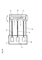
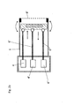
- three drive elements 4, 4 'and 4 "are arranged here, which are connected via mechanical connections 6, 6 'and 6 "to the converter housing 3, in which a piezoelectric crystal 2 is arranged FIGS. 2a) and 2 B ) differ from each other in that the ultrasonic probe according to Fig. 2a ) has a fixed cover 8, while the ultrasonic probe according to Fig. 2b ) has a membrane 8 'as a contact surface.
- Fig. 3 an ultrasonic probe is shown, the two drive elements 4 and 4 ', which are connected via two rods 6 and 6' to the converter housing 3.
- a tilting of the converter housing 3 is possible.
- a fixing element 21 is arranged, via which the converter housing 3 is fixedly connected to the upper part of the probe housing 1.
- Fig. 5 a further variant of the ultrasonic probe is shown, in which the converter housing 3 is connected by means of a punch 7.
- This stamp 7 passes through a bearing 22 and is at the other end with two drive elements 8 and 8 'in mechanical connection.
- a converter housing 3 is shown, in which an ultrasonic transducer 2 is integrated. Furthermore, the converter housing 3 has on the lower side a conical recess 10 for focusing the ultrasound.
- Fig. 7 an ultrasound monitoring system according to the invention is shown, which consists of the ultrasound probe 101, which interacts with a patient stands, the control unit 102 and the base unit 103 consists.
- the probe 101 has a piezoelectric crystal 105 and an actuator.
- the piezoelectric crystal 105 receives an excitation signal from the Doppler hardware, while on the other side the piezoelectric crystal 105 also passes signals to the Doppler hardware 110.
- This captured signal causes the Doppler hardware 110 to drive the control unit 102, which has a search algorithm 107 and calibration data for the probe 108. Based on these data, a check of the actuator 106 can take place.
- a software is also installed, with which an optimization of the transmission signal takes place.
Landscapes
- Engineering & Computer Science (AREA)
- Physics & Mathematics (AREA)
- Health & Medical Sciences (AREA)
- Life Sciences & Earth Sciences (AREA)
- Acoustics & Sound (AREA)
- Radar, Positioning & Navigation (AREA)
- Remote Sensing (AREA)
- Radiology & Medical Imaging (AREA)
- Molecular Biology (AREA)
- Biophysics (AREA)
- Nuclear Medicine, Radiotherapy & Molecular Imaging (AREA)
- Pathology (AREA)
- Computer Networks & Wireless Communication (AREA)
- Biomedical Technology (AREA)
- Heart & Thoracic Surgery (AREA)
- Medical Informatics (AREA)
- General Physics & Mathematics (AREA)
- Surgery (AREA)
- Animal Behavior & Ethology (AREA)
- General Health & Medical Sciences (AREA)
- Public Health (AREA)
- Veterinary Medicine (AREA)
- Multimedia (AREA)
- Ultra Sonic Daignosis Equipment (AREA)
Abstract
Die Erfindung betrifft eine Ultraschall-Sonde enthaltend ein Sonden-Gehäuse, in dem mindestens ein Ultraschall-Wandler in mindestens einem Wandler-Gehäuse angeordnet ist sowie mindestens zwei Antriebselemente für das Wandler-Gehäuse, wobei das Sonden-Gehäuse zumindest bereichsweise mit einem Ultraschall übertragenden Medium gefüllt ist. Weiterhin betrifft die Erfindung ein Ultraschall-Monitoring-System, in dem eine derartige Ultraschall-Sonde zusammen mit einer Sondensteuerung, einem Ultraschall-Generator, einer Signalanzeige sowie einer Haltevorrichtung enthalten ist. Weiterhin betrifft die Erfindung die Verwendung der Ultraschall-Sonden für das Monitoring von Schlaganfall-Patienten, das Monitoring bei Operationen sowie das Monitoring von Dialyse-Shunts.
Description
- Die Erfindung betrifft eine Ultraschall-Sonde enthaltend ein Sonden-Gehäuse, in dem mindestens ein Ultraschall-Wandler in mindestens einem Wandler-Gehäuse angeordnet ist sowie mindestens zwei Antriebselemente für das Wandler-Gehäuse, wobei das Sonden-Gehäuse zumindest bereichsweise mit einem Ultraschall übertragenden Medium gefüllt ist. Weiterhin betrifft die Erfindung ein Ultraschall-Monitoring-System, in dem eine derartige Ultraschall-Sonde zusammen mit einer Sondensteuerung, einem Ultraschall-Generator, einer Signalanzeige sowie einer Haltevorrichtung enthalten ist. Weiterhin betrifft die Erfindung die Verwendung der Ultraschall-Sonden für das Monitoring von Schlaganfall-Patienten, das Monitoring bei Operationen sowie das Monitoring von Dialyse-Shunts.
- In der Gefäßdiagnostik ist der Ultraschall-Doppler in der heutigen Medizin unverzichtbar, da die Anwendung einfach, nicht-invasiv sowie kontinuierlich durchführbar ist.
- Das Prinzip basiert darauf, dass eine Ultraschall-Sonde über ein akustisches Kopplungsmedium mit dem zum Gefäß benachbarten Gewebe in Kontakt gebracht wird. Es erfolgt eine Beschallung des zu untersuchenden Gefäßes. Die roten Blutkörperchen wiederum reflektieren das Signal und verursachen einen Doppler-Shift. Die Sonde wird in der Regel mit einer Frequenz zwischen 2 und 8 MHz betrieben.
- Seit 1982 wird der transkranielle Doppler (TCD) zur Blutflussdiagnostik der Hirngefäße eingesetzt. Dabei wird ein gepulster Doppler verwendet, d.h. die Sonde enthält nur einen Piezokristall, welcher abwechselnd als Sender und Empfänger geschaltet ist. Durch Einstellen des Zeitfensters für den Empfang lässt sich die Tiefe festlegen, aus der ein Echo ausgewertet werden soll.
- Der transkranielle Doppler hat ein breit gefächertes Anwendungsfeld, insbesondere auch in länger andauernden Untersuchungen. Die Schwierigkeit besteht allerdings darin, die Gefäße in der Tiefe zu orten und das Signal durch Bewegung nicht wieder zu verlieren.
- Im Stand der Technik wurden diese Probleme bislang durch den Einsatz von Fixiervorrichtungen gelöst, z.B. helmartige Fixiervorrichtungen, in die eine Doppler-Sonde integriert ist (
US 5,070,880 undUS 5,409,005 undUS 6,547,737 B2 ). Derartige Systeme haben allerdings den Nachteil, dass derartige Helme das Wohlbefinden des Patienten stark einschränken können. - Aus der
DE 298 23 361 U1 ist eine Ultraschall-Vorrichtung bekannt, die eine am menschlichen Kopf befestigbare Halteeinheit aufweist, an welcher die Sondeneinheit verstell- und daraufhin fixierbar ist, um bei möglicher Kopfbewegung die Ultraschallsonde stets in der gewählten, optimalen Position zu halten. Auch bei diesem System erfolgt demnach eine Änderung der Position der Ultraschall-Sonde in der Halteeinheit. Auch hier tritt demnach der Nachteil auf, dass die Positionierung nicht nur zur Halteeinheit, sondern auch zum menschlichen Kopf verändert wird und das Wohlbefinden des Patienten stark einschränkt. - Ausgehend hiervon war es Aufgabe der vorliegenden Erfindung, eine Ultraschall-Sonde bereitzustellen, die nach Einstellung einer optimalen Signalstärke dieses Signal auch bei Bewegung des zu untersuchenden Körperteils beibehalten kann.
- Diese Aufgabe wird durch die gattungsgemäße Ultraschall-Sonde mit den kennzeichnenden Merkmalen des Anspruchs 1 und das Ultraschall-Monitoring-System mit den Merkmalen des Anspruchs 15 gelöst. Die weiteren abhängigen Ansprüche zeigen vorteilhafte Weiterbildungen auf. In Anspruch 17 werden erfindungsgemäße Verwendungen angegeben.
- Erfindungsgemäß wird eine Ultraschall-Sonde bereitgestellt, die ein Sonden-Gehäuse aufweist, in dem mindestens ein Ultraschall-Wandler in mindestens einem Wandler-Gehäuse angeordnet ist. Weiterhin sind mindestens zwei Antriebselemente für das Wandler-Gehäuse vorgesehen. Das Sonden-Gehäuse ist dabei zumindest bereichsweise mit einem Ultraschall übertragenden Medium gefüllt.
- Die erfindungsgemäße Ultraschall-Sonde zeichnet sich dadurch aus, dass das mindestens eine Wandler-Gehäuse mit den mindestens zwei Antriebselementen in mechanischer Verbindung steht und damit das mindestens eine Wandler-Gehäuse in seiner räumlichen Position relativ zum Sonden-Gehäuse ausrichtbar ist.
- In einer ersten bevorzugten Ausführungsform ist dabei das mindestens eine Wandler-Gehäuse an drei Punkten mit jeweils einem Antriebselement mechanisch verbunden. Somit kann die Positionierung des Wandler-Gehäuses relativ zum Sonden-Gehäuse über drei verschiedene Antriebselemente eingestellt werden, was eine größtmögliche Flexibilität bezüglich der Ausrichtung des Wandler-Gehäuses ermöglicht.
- Eine zweite erfindungsgemäße Ausführungsform sieht vor, dass das mindestens eine Wandler-Gehäuse an einem Punkt am Sonden-Gehäuse form- oder stoffschlüssig fixiert ist. An zwei anderen Punkten ist das Wandler-Gehäuse mit jeweils einem Antriebselement mechanisch verbunden. Über diese beiden Antriebselemente kann dann die Position des Wandler-Gehäuses verändert werden.
- Eine weitere erfindungsgemäße Ausführungsform sieht vor, dass das mindestens eine Wandler-Gehäuse einen Stempel aufweist. Dieser Stempel befindet sich in zwei Lagerungen, wobei der Stempel mit jeweils einem Antriebselement mechanisch verbunden ist, so dass durch das Antriebselement eine Änderung der Position des Stempels und damit des Wandler-Gehäuses erfolgt. Ebenso ist es möglich, dass die Antriebselemente nicht am Stempel, sondern direkt am Wandler-Gehäuse angreifen.
- Als Antriebselemente kommen bevorzugt Linearantriebe, Seilzüge und/oder Federaufhängungen in Frage.
- Allen Varianten ist gemein, dass eine freie Ausrichtung des Wandler-Gehäuses in alle drei Raumrichtungen ermöglicht wird.
- Der mindestens eine Ultraschall-Wandler ist vorzugsweise ein ultraschallerzeugendes Element, besonders bevorzugt ein Piezo-Kristall.
- Es ist weiter bevorzugt, dass das Ultraschall-übertragende Medium ein flüssiges Medium mit einer akustischen Impedanz im Bereich von 0,6 bis 3,5 MegaRayl (1 Rayl = 1 kg/sm2) ist. Besonders bevorzugt sind hier Wasser bzw. andere organische flüssige Medien, die den Ultraschall transportieren. Hierzu zählen Wasser, Alkohole, Glycerin und/oder Öle.
- Vorzugsweise weist die Ultraschall-Sonde eine obere für Ultraschall zumindest teilweise durchlässige Abdeckung zum Inkontaktbringen mit dem menschlichen Körper auf. Hierbei handelt es sich bevorzugt um einen Deckel oder eine Membran. Beim Inkontaktbringen mit dem menschlichen Körper wird dann auf die zu untersuchende Körperstelle ein akustisches Kopplungsgel aufgetragen, um den Übergang zwischen Ultraschall-Sonde und menschlichem Körper luftfrei zu ermöglichen.
- Eine bevorzugte Variante sieht vor, dass im Sonden-Gehäuse der Bereich zwischen der oberen Abdeckung und dem Wandler-Gehäuse mit einem den Ultraschall übertragenden Medium gefüllt ist. Der restliche Bereich, d.h. der Bereich hinter dem Ultraschall-Wandler (betrachtet in Richtung der oberen Abdeckung), ist mit einem den Ultraschall nicht übertragenden Medium, z.B. Luft, versehen.
- Diesbezüglich ist es bevorzugt, dass das Wandler-Gehäuse hinter dem Ultraschall-erzeugenden Element ein sog. Backing aufweist. Hierbei handelt es sich um einen Luftspalt, der verhindert, dass eine Abstrahlung von Ultraschallwellen nach hinten, also in die vom menschlichen Körper abgewandte Richtung, erfolgt. Ein derartiges Backing kann z.B. dadurch realisiert werden, dass auf der der oberen Abdeckung abgewandten Seite des Ultraschall-erzeugenden Elementes mindestens ein Steg angeordnet ist, auf dem eine Abdeckplatte befestigt ist, wodurch sich zwischen den Stegen Lufträume bilden können.
- Eine weitere bevorzugte Ausführungsform sieht vor, dass das Wandler-Gehäuse auf der der oberen Abdeckung zugewandten Seite des Ultraschall-Wandlers eine Scheibe mit einer kegelförmigen Vertiefung zur Fokussierung des Ultraschalls aufweist.
- Eine weitere Variante sieht vor, dass die Ultraschall-Sonde eine Linse aufweist, die zwischen oberer Abdeckung und Wandler-Gehäuse angeordnet ist. So kann die Linse z.B. auf dem Wandler-Gehäuse aufgeklebt sein.
- Es ist weiter bevorzugt, dass die Komponenten der Ultraschall-Sonde, insbesondere das Sonden-Gehäuse, das Wandler-Gehäuse und das Ultraschall übertragende Medium, aus biokompatiblen Materialien bestehen, wodurch der problemlose Einsatz im Gesundheits-Sektor ermöglicht wird.
- Erfindungsgemäß wird ebenso ein Ultraschall-Monitoring-System bereitgestellt, das die folgenden Komponenten enthält:
- eine zuvor beschriebene Ultraschall-Sonde,
- eine Sondensteuerung,
- einen Ultraschall-Generator,
- eine Signalanzeige für das Monitoring des Ultraschall-Signals sowie
- eine Haltevorrichtung zur Fixierung der Ultraschall-Sonde am menschlichen Körper.
- Vorzugsweise ist die Haltevorrichtung ein Helm oder eine Brille.
- Das ultraschallerzeugende Element erzeugt vorzugsweise ein Ultraschallsignal mit einer Frequenz im Bereich von 2 MHz bis 16 MHz, bevorzugt von 2 MHz bis 8 MHz.
- Verwendung finden die erfindungsgemäßen Ultraschall-Sonden für das Monitoring bei Herzoperationen, Operationen an den Schlagadern sowie Operationen am Gehirn. Ebenso kann die Ultraschall-Sonde für das Monitoring von Schlaganfall-Patienten sowie für das Monitoring von Dialyse-Shunts eingesetzt werden.
- Anhand der nachfolgenden Figuren soll der erfindungsgemäße Gegenstand näher erläutert werden, ohne diesen auf die hier gezeigten speziellen Ausführungsformen einschränken zu wollen.
-
Fig. 1 zeigt eine erste erfindungsgemäße Ausführungsform der Ultraschall-Sonde. -
Fig. 2a ) und2b ) zeigen eine erfindungsgemäße Ausführungsform mit jeweils drei Antriebselementen. -
Fig. 3 zeigt eine erfindungsgemäße Variante der Ultraschall-Sonde mit zwei Antriebselementen. -
Fig. 4 zeigt eine erfindungsgemäße Ausführungsform mit zwei Antriebselementen sowie einem Fixierelement. -
Fig. 5 zeigt eine erfindungsgemäße Ausführungsform mit einem gelagerten Stempel. -
Fig. 6 zeigt ein Wandler-Gehäuse der erfindungsgemäßen Ultraschall-Sonde. - In
Fig. 1 ist ein Sonden-Gehäuse 1 dargestellt, in dem der Ultraschall-Wandler 2 in einem Wandler-Gehäuse 3 untergebracht ist. Weiterhin befindet sich in dem Sonden-Gehäuse ein den Ultraschall übertragendes Medium 5. Im Sonden-Gehäuse 1 sind zusätzlich Antriebselemente 4 und 4' angeordnet, die über eine mechanische Verbindung in Form einer Stange 6 und 6' mit dem Wandler-Gehäuse 3 verbunden sind. Der Ultraschall-Wandler 2 ist über elektrische Kontaktierungen 20 mit einer Ultraschall-Basiseinheit (in der Figur nicht dargestellt) verbunden. An dem anderen Ende der Ultraschall-Sonde ist eine Abdeckung 8, z.B. in Form einer Membran, angeordnet, die als Kontaktfläche zum menschlichen Körper dient. - Die
Figuren 2a ) und2b ) sind im Wesentlichen an die Ausführungsform gemäßFigur 1 angelehnt. Allerdings sind hier drei Antriebselemente 4, 4' und 4" angeordnet, die über mechanische Verbindungen 6, 6' und 6" mit dem Wandler-Gehäuse 3, in dem ein Piezokristall 2 angeordnet ist, verbunden sind. DieFiguren 2a) und2b ) unterscheiden sich dadurch voneinander, dass die Ultraschall-Sonde gemäßFig. 2a ) eine feste Abdeckung 8 aufweist, während die Ultraschall-Sonde gemäßFig. 2b ) eine Membran 8' als Kontaktfläche aufweist. - In
Fig. 3 ist eine Ultraschall-Sonde dargestellt, die zwei Antriebselemente 4 und 4' aufweist, die über zwei Stangen 6 und 6' mit dem Wandler-Gehäuse 3 verbunden sind. Durch diese Anordnung ist eine Verkippung des Wandler-Gehäuses 3 möglich. - In
Fig. 4 ist zusätzlich zu den beiden Antriebselementen ein Fixierelement 21 angeordnet, über das das Wandler-Gehäuse 3 fix mit dem oberen Teil des Sonden-Gehäuses 1 verbunden ist. - In
Fig. 5 ist eine weitere Variante der Ultraschall-Sonde dargestellt, in der das Wandler-Gehäuse 3 mittels eines Stempels 7 verbunden ist. Dieser Stempel 7 durchläuft ein Lager 22 und steht am anderen Ende mit zwei Antriebselementen 8 und 8' in mechanischer Verbindung. - In
Fig. 6 ist ein Wandler-Gehäuse 3 dargestellt, in das ein Ultraschall-Wandler 2 integriert ist. Weiterhin weist das Wandler-Gehäuse 3 auf der unteren Seite eine kegelförmige Vertiefung 10 zur Fokussierung des Ultraschalls auf. - In
Fig. 7 ist ein erfindungsgemäßes Ultraschall-Monitoring-System dargestellt, das aus der Ultraschall-Sonde 101, die in Wechselwirkung mit einem Patienten steht, der Steuerungseinheit 102 und der Basiseinheit 103 besteht. Die Sonde 101 weist einen Piezokristall 105 sowie einen Aktuator auf. Dabei erhält der Piezokristall 105 von der Doppler-Hardware ein Anregungssignal, während auf der anderen Seite der Piezokristall 105 ebenso Signale an die Doppler-Hardware 110 weitergibt. Dieses aufgenommene Signal veranlasst die Doppler-Hardware 110 die Steuerungseinheit 102 anzusteuern, die einen Suchalgorhythmus 107 und Kalibrationsdaten für die Sonde 108 aufweist. Anhand dieser Daten kann eine Kontrolle des Aktuators 106 erfolgen. In der Basiseinheit ist weiterhin eine Software installiert, mit der eine Optimierung des Sendesignals erfolgt.
Claims (17)
- Ultraschall-Sonde enthaltend ein Sonden-Gehäuse (1), in dem mindestens ein Ultraschall-Wandler (2) in mindestens einem Wandler-Gehäuse (3) angeordnet ist, sowie mindestens zwei Antriebselemente (4, 4', 4") für das Wandler-Gehäuse (3), wobei das Sonden-Gehäuse (1) zumindest bereichsweise mit einem Ultraschall übertragenden Medium (5) gefüllt ist,
dadurch gekennzeichnet, dass das mindestens eine Wandler-Gehäuse (3) mit den mindestens zwei Antriebselementen (4, 4', 4") in mechanischer Verbindung (6, 6') steht und damit das mindestens eine Wandler-Gehäuse (3) in seiner räumlichen Position relativ zum Sonden-Gehäuse (1) ausrichtbar ist. - Ultraschall-Sonde nach Anspruch 1,
dadurch gekennzeichnet, dass das mindestens eine Wandler-Gehäuse (3) an drei Punkten mit jeweils einem Antriebselement (4, 4', 4") mechanisch verbunden ist. - Ultraschall-Sonde nach Anspruch 1,
dadurch gekennzeichnet, dass das mindestens eine Wandler-Gehäuse (3) an einem Punkt am Sonden-Gehäuse (1) fixiert ist und an zwei Punkten mit jeweils einem Antriebselement (4, 4') mechanisch verbunden ist. - Ultraschall-Sonde nach Anspruch 1,
dadurch gekennzeichnet, dass das mindestens eine Wandler-Gehäuse (3) einen gelagerten Stempel (7) aufweist, wobei der Stempel (7) an zwei Punkten mit jeweils einem Antriebselement (8, 8') mechanisch verbunden ist. - Ultraschall-Sonde nach einem der vorhergehenden Ansprüche,
dadurch gekennzeichnet, dass die Antriebselemente (4, 4', 4", 8, 8') Linearantriebe, Seilzüge und/oder Federaufhängungen sind. - Ultraschall-Sonde nach einem der vorhergehenden Ansprüche,
dadurch gekennzeichnet, dass das Wandler-Gehäuse (3) in drei Raumrichtungen frei ausrichtbar ist. - Ultraschall-Sonde nach einem der vorhergehenden Ansprüche,
dadurch gekennzeichnet, dass das der mindestens eine Ultraschall-Wandler (2) ein ultraschallerzeugendes Element, insbesondere ein Piezo-Kristall ist. - Ultraschall-Sonde nach dem vorhergehenden Anspruch,
dadurch gekennzeichnet, dass das ultraschallerzeugende Element ein Ultraschallsignal mit einer Frequenz im Bereich von 2 MHz bis 16 MHz, insbesondere von 2 MHz bis 8 MHz erzeugt. - Ultraschall-Sonde nach einem der vorhergehenden Ansprüche,
dadurch gekennzeichnet, dass das Ultraschall übertragende Medium (5) ein flüssiges Medium mit einer akustischen Impedanz im Bereich von 0,6 bis 3,5 MegaRayl ist, insbesondere Wasser oder organische flüssige Medien, hier insbesondere Alkohole, Glycerin oder Öle. - Ultraschall-Sonde nach einem der vorhergehenden Ansprüche,
dadurch gekennzeichnet, dass die Ultraschall-Sonde eine obere für Ultraschall zumindest teilweise durchlässige Abdeckung (9) zum Inkontaktbringen mit dem menschlichen Körper aufweist, insbesondere ein Deckel oder eine Membran. - Ultraschall-Sonde nach einem der vorhergehenden Ansprüche,
dadurch gekennzeichnet, dass im Sonden-Gehäuse (1) der Bereich zwischen der oberen Abdeckung (9) und dem Wandler-Gehäuse (3) mit einem den Ultraschall übertragenden Medium (5) und der andere Bereich mit einem den Ultraschall nicht übertragenden Medium gefüllt. - Ultraschall-Sonde nach einem der vorhergehenden Ansprüche,
dadurch gekennzeichnet, dass das Wandler-Gehäuse (3) auf der auf der der oberen Abdeckung (9) zugewandten Seite des Ultraschall-Wandlers (2) eine Scheibe mit einer kegelförmigen Vertiefung (10) zur Fokussierung des Ultraschalls aufweist. - Ultraschall-Sonde nach einem der vorhergehenden Ansprüche,
dadurch gekennzeichnet, dass die Ultraschall-Sonde eine Linse (11) aufweist, die zwischen oberer Abdeckung (9) und Wandler-Gehäuse (3) angeordnet ist. - Ultraschall-Sonde nach einem der vorhergehenden Ansprüche,
dadurch gekennzeichnet, dass die Komponenten der Ultraschall-Sonde, insbesondere das Sonden-Gehäuse (1), das Wandler-Gehäuse (3) und das Ultraschall übertragende Medium (5) aus biokompatiblen Materialien bestehen. - Ultraschall-Monitoring-System enthaltend• eine Ultraschall-Sonde nach einem der vorhergehenden Ansprüche,• eine Sondensteuerung (12),• einen Ultraschall-Generator (13),• eine Signalanzeige (14) für das Monitoring des Ultraschall-Signals sowie• eine Haltevorrichtung zur Fixierung der Ultraschall-Sonde am menschlichen Körper.
- Ultraschall-Monitoring-System nach Anspruch 14, dadurch gekennzeichnet, dass die Haltevorrichtung ein Helm oder eine Brille ist.
- Verwendung der Ultraschall-Sonde nach einem der Ansprüche 1 bis 13 für das Monitoring bei Herzoperationen, Operationen an den Schlagadern sowie Operationen am Gehirn, für das Monitoring von Schlaganfall-Patienten sowie für Monitoring von Dialyse-Shunts.
Priority Applications (1)
| Application Number | Priority Date | Filing Date | Title |
|---|---|---|---|
| EP10016067A EP2468190A1 (de) | 2010-12-23 | 2010-12-23 | Ultraschall-Sonde, Ultraschall-Monitoring-System sowie deren Verwendung |
Applications Claiming Priority (1)
| Application Number | Priority Date | Filing Date | Title |
|---|---|---|---|
| EP10016067A EP2468190A1 (de) | 2010-12-23 | 2010-12-23 | Ultraschall-Sonde, Ultraschall-Monitoring-System sowie deren Verwendung |
Publications (1)
| Publication Number | Publication Date |
|---|---|
| EP2468190A1 true EP2468190A1 (de) | 2012-06-27 |
Family
ID=43901132
Family Applications (1)
| Application Number | Title | Priority Date | Filing Date |
|---|---|---|---|
| EP10016067A Withdrawn EP2468190A1 (de) | 2010-12-23 | 2010-12-23 | Ultraschall-Sonde, Ultraschall-Monitoring-System sowie deren Verwendung |
Country Status (1)
| Country | Link |
|---|---|
| EP (1) | EP2468190A1 (de) |
Cited By (3)
| Publication number | Priority date | Publication date | Assignee | Title |
|---|---|---|---|---|
| CN104739452A (zh) * | 2013-12-30 | 2015-07-01 | 深圳迈瑞生物医疗电子股份有限公司 | 一种超声成像装置及方法 |
| CN112037479A (zh) * | 2020-09-25 | 2020-12-04 | 华侨大学 | 一种锂电池热失控监测预警系统及方法 |
| CN115685215A (zh) * | 2022-11-22 | 2023-02-03 | 南方科技大学 | 空气耦合超声波成像装置和机器人 |
Citations (15)
| Publication number | Priority date | Publication date | Assignee | Title |
|---|---|---|---|---|
| US3425507A (en) * | 1966-12-22 | 1969-02-04 | Mobil Oil Corp | Sonic system for locating objects in the bottom of a borehole |
| US4637256A (en) * | 1983-06-23 | 1987-01-20 | Matsushita Electric Industrial Co., Ltd. | Ultrasonic probe having dual-motion transducer |
| US5070880A (en) | 1990-10-30 | 1991-12-10 | St. Louis University | Transcranial Doppler transducer housing stabilizer |
| US5409005A (en) | 1993-10-07 | 1995-04-25 | Medasonics, Inc. | Transcranial doppler probe wheel and track/bar fixation assembly |
| US5535751A (en) * | 1994-12-22 | 1996-07-16 | Morphometrix Technologies Inc. | Confocal ultrasonic imaging system |
| US5598845A (en) * | 1995-11-16 | 1997-02-04 | Stellartech Research Corporation | Ultrasound transducer device for continuous imaging of the heart and other body parts |
| US5647364A (en) * | 1995-02-15 | 1997-07-15 | Ultra-Scan Corporation | Ultrasonic biometric imaging and identity verification system |
| US5779639A (en) * | 1996-11-21 | 1998-07-14 | Hewlett-Packard Company | Ultrasound probe with offset angle tip |
| DE29823361U1 (de) | 1997-11-20 | 1999-06-24 | DWL Elektronische Systeme GmbH, 78354 Sipplingen | Ultraschallvorrichtung und Verwendung einer solchen Ultraschallvorrichtung |
| US20020042574A1 (en) * | 1998-11-18 | 2002-04-11 | Biosonix Ltd. | Dual ultrasonic transducer probe for blood flow measurment, and blood vessel diameter determination method |
| US20020103436A1 (en) * | 2000-01-14 | 2002-08-01 | Njemanze Philip Chidi | Intelligent transcranial doppler probe |
| US20050124889A1 (en) * | 2003-12-05 | 2005-06-09 | Aime Flesch | Array transducer for 3D tilting probes |
| EP2113201A2 (de) * | 2008-04-14 | 2009-11-04 | iVu Imaging Corporation | Bewegliches Ultraschallelement zur Verwendung in medizinischen Diagnosevorrichtungen |
| US20100063398A1 (en) * | 2008-09-10 | 2010-03-11 | Halmann Menachem Nahi | Ultrasound probe for guidance procedures |
| WO2010075553A1 (en) * | 2008-12-24 | 2010-07-01 | Guardsman Scientific, Inc. | Peripheral ultrasound device |
-
2010
- 2010-12-23 EP EP10016067A patent/EP2468190A1/de not_active Withdrawn
Patent Citations (16)
| Publication number | Priority date | Publication date | Assignee | Title |
|---|---|---|---|---|
| US3425507A (en) * | 1966-12-22 | 1969-02-04 | Mobil Oil Corp | Sonic system for locating objects in the bottom of a borehole |
| US4637256A (en) * | 1983-06-23 | 1987-01-20 | Matsushita Electric Industrial Co., Ltd. | Ultrasonic probe having dual-motion transducer |
| US5070880A (en) | 1990-10-30 | 1991-12-10 | St. Louis University | Transcranial Doppler transducer housing stabilizer |
| US5409005A (en) | 1993-10-07 | 1995-04-25 | Medasonics, Inc. | Transcranial doppler probe wheel and track/bar fixation assembly |
| US5535751A (en) * | 1994-12-22 | 1996-07-16 | Morphometrix Technologies Inc. | Confocal ultrasonic imaging system |
| US5647364A (en) * | 1995-02-15 | 1997-07-15 | Ultra-Scan Corporation | Ultrasonic biometric imaging and identity verification system |
| US5598845A (en) * | 1995-11-16 | 1997-02-04 | Stellartech Research Corporation | Ultrasound transducer device for continuous imaging of the heart and other body parts |
| US5779639A (en) * | 1996-11-21 | 1998-07-14 | Hewlett-Packard Company | Ultrasound probe with offset angle tip |
| DE29823361U1 (de) | 1997-11-20 | 1999-06-24 | DWL Elektronische Systeme GmbH, 78354 Sipplingen | Ultraschallvorrichtung und Verwendung einer solchen Ultraschallvorrichtung |
| US20020042574A1 (en) * | 1998-11-18 | 2002-04-11 | Biosonix Ltd. | Dual ultrasonic transducer probe for blood flow measurment, and blood vessel diameter determination method |
| US20020103436A1 (en) * | 2000-01-14 | 2002-08-01 | Njemanze Philip Chidi | Intelligent transcranial doppler probe |
| US6547737B2 (en) | 2000-01-14 | 2003-04-15 | Philip Chidi Njemanze | Intelligent transcranial doppler probe |
| US20050124889A1 (en) * | 2003-12-05 | 2005-06-09 | Aime Flesch | Array transducer for 3D tilting probes |
| EP2113201A2 (de) * | 2008-04-14 | 2009-11-04 | iVu Imaging Corporation | Bewegliches Ultraschallelement zur Verwendung in medizinischen Diagnosevorrichtungen |
| US20100063398A1 (en) * | 2008-09-10 | 2010-03-11 | Halmann Menachem Nahi | Ultrasound probe for guidance procedures |
| WO2010075553A1 (en) * | 2008-12-24 | 2010-07-01 | Guardsman Scientific, Inc. | Peripheral ultrasound device |
Cited By (7)
| Publication number | Priority date | Publication date | Assignee | Title |
|---|---|---|---|---|
| CN104739452A (zh) * | 2013-12-30 | 2015-07-01 | 深圳迈瑞生物医疗电子股份有限公司 | 一种超声成像装置及方法 |
| WO2015100906A1 (zh) * | 2013-12-30 | 2015-07-09 | 深圳迈瑞生物医疗电子股份有限公司 | 一种超声成像装置及方法 |
| CN104739452B (zh) * | 2013-12-30 | 2019-02-12 | 深圳迈瑞生物医疗电子股份有限公司 | 一种超声成像装置及方法 |
| US11231431B2 (en) | 2013-12-30 | 2022-01-25 | Shenzhen Mindray Bio-Medical Electronics Co., Ltd. | Ultrasound imaging device and imaging method thereof |
| US11754577B2 (en) | 2013-12-30 | 2023-09-12 | Shenzhen Mindray Bio-Medical Electronics Co., Ltd. | Ultrasound imaging device and imaging method thereof |
| CN112037479A (zh) * | 2020-09-25 | 2020-12-04 | 华侨大学 | 一种锂电池热失控监测预警系统及方法 |
| CN115685215A (zh) * | 2022-11-22 | 2023-02-03 | 南方科技大学 | 空气耦合超声波成像装置和机器人 |
Similar Documents
| Publication | Publication Date | Title |
|---|---|---|
| EP0631491B1 (de) | Vorrichtung zum orten und punktieren von blutgefässen | |
| DE4443947B4 (de) | Endoskop | |
| DE19840405B4 (de) | Vorrichtung zur Fixierung der weiblichen Brust bei medizintechnischen Anwendungen | |
| DE69625924T2 (de) | Ultraschallanordnung für die kontinuierliche bilderzeugung vom herz und andren körperteilen | |
| DE102006056993A1 (de) | Drehbares Wandlerarray zur volumetrischen Ultraschallbildgebung | |
| DE2529112A1 (de) | Ultraschall-applikator fuer die ultraschallabtastung von koerpern | |
| DE2619231A1 (de) | Verfahren und vorrichtung zur ultraschallpruefung | |
| DE112016005463T5 (de) | Handgehaltenes instrument für endoskopische chirurgie | |
| EP1749488A2 (de) | Stosswellentherapiegerät mit Bildgewinnung | |
| DE69812661T2 (de) | Vorrichtung zur befestigung an einem schädelknochen und bausatz welcher solch eine vorrichtung enthält | |
| DE3617032C2 (de) | Lithotripsiegerät mit extrakorporalem Stoßwellengenerator | |
| EP0343432A2 (de) | Vorrichtung zur räumlichen Ultraschall-Ortung von Konkrementen | |
| DE10305603B4 (de) | Einrichtung zum Erzeugen eines dreidimensionalen Ultraschallbildes | |
| DE102011083360A1 (de) | Instrument zur Pedikelpräparation mit Ultraschallsonde | |
| EP3412207A1 (de) | Mammographie-bildgebung | |
| EP2515763A1 (de) | Vorrichtung zur gewinnung von bilddaten von knöchernen strukturen, insbesondere zur diagnose von knochenfrakturen | |
| EP2271439B1 (de) | Multifrequenz-sende- und empfangseinheit für mediengebundene wellen | |
| DE3714747C2 (de) | ||
| DE102005048049B4 (de) | Vorrichtung zur bildgestützten Mammadiagnose und -therapie | |
| WO2000062091A1 (de) | Vorrichtung und verfahren für die 3d-echtzeitsonographie | |
| DE19936554C2 (de) | Vorrichtung zur Unterstützung der Elastographie | |
| WO2015044255A1 (de) | Ultraschallsystem mit dreidimensionaler volumendarstellung | |
| DE102010042012A1 (de) | Instrument mit Ultraschallsonde zur Pedikelpräparation | |
| DE19755974C2 (de) | Vorrichtung und Verfahren zur Gewinnung von 3D-Ultraschalldaten | |
| DE102006000838B4 (de) | Ultraschallvorrichtung für medizinische Anwendungen |
Legal Events
| Date | Code | Title | Description |
|---|---|---|---|
| AK | Designated contracting states |
Kind code of ref document: A1 Designated state(s): AL AT BE BG CH CY CZ DE DK EE ES FI FR GB GR HR HU IE IS IT LI LT LU LV MC MK MT NL NO PL PT RO RS SE SI SK SM TR |
|
| AX | Request for extension of the european patent |
Extension state: BA ME |
|
| PUAI | Public reference made under article 153(3) epc to a published international application that has entered the european phase |
Free format text: ORIGINAL CODE: 0009012 |
|
| STAA | Information on the status of an ep patent application or granted ep patent |
Free format text: STATUS: THE APPLICATION IS DEEMED TO BE WITHDRAWN |
|
| 18D | Application deemed to be withdrawn |
Effective date: 20130103 |