EP2468191B1 - Appareil de diagnostic par ultrasons pour la fourniture d'une carte d'indices d'intérêt - Google Patents
Appareil de diagnostic par ultrasons pour la fourniture d'une carte d'indices d'intérêt Download PDFInfo
- Publication number
- EP2468191B1 EP2468191B1 EP11195229.7A EP11195229A EP2468191B1 EP 2468191 B1 EP2468191 B1 EP 2468191B1 EP 11195229 A EP11195229 A EP 11195229A EP 2468191 B1 EP2468191 B1 EP 2468191B1
- Authority
- EP
- European Patent Office
- Prior art keywords
- map
- ultrasound
- ultrasound diagnosis
- diagnosis apparatus
- region
- Prior art date
- Legal status (The legal status is an assumption and is not a legal conclusion. Google has not performed a legal analysis and makes no representation as to the accuracy of the status listed.)
- Active
Links
Images


Classifications
-
- A—HUMAN NECESSITIES
- A61—MEDICAL OR VETERINARY SCIENCE; HYGIENE
- A61B—DIAGNOSIS; SURGERY; IDENTIFICATION
- A61B8/00—Diagnosis using ultrasonic, sonic or infrasonic waves
- A61B8/58—Testing, adjusting or calibrating the diagnostic device
-
- A—HUMAN NECESSITIES
- A61—MEDICAL OR VETERINARY SCIENCE; HYGIENE
- A61B—DIAGNOSIS; SURGERY; IDENTIFICATION
- A61B8/00—Diagnosis using ultrasonic, sonic or infrasonic waves
- A61B8/52—Devices using data or image processing specially adapted for diagnosis using ultrasonic, sonic or infrasonic waves
- A61B8/5215—Devices using data or image processing specially adapted for diagnosis using ultrasonic, sonic or infrasonic waves involving processing of medical diagnostic data
- A61B8/5223—Devices using data or image processing specially adapted for diagnosis using ultrasonic, sonic or infrasonic waves involving processing of medical diagnostic data for extracting a diagnostic or physiological parameter from medical diagnostic data
-
- A—HUMAN NECESSITIES
- A61—MEDICAL OR VETERINARY SCIENCE; HYGIENE
- A61B—DIAGNOSIS; SURGERY; IDENTIFICATION
- A61B8/00—Diagnosis using ultrasonic, sonic or infrasonic waves
- A61B8/54—Control of the diagnostic device
-
- G—PHYSICS
- G01—MEASURING; TESTING
- G01S—RADIO DIRECTION-FINDING; RADIO NAVIGATION; DETERMINING DISTANCE OR VELOCITY BY USE OF RADIO WAVES; LOCATING OR PRESENCE-DETECTING BY USE OF THE REFLECTION OR RERADIATION OF RADIO WAVES; ANALOGOUS ARRANGEMENTS USING OTHER WAVES
- G01S7/00—Details of systems according to groups G01S13/00, G01S15/00, G01S17/00
- G01S7/52—Details of systems according to groups G01S13/00, G01S15/00, G01S17/00 of systems according to group G01S15/00
- G01S7/52017—Details of systems according to groups G01S13/00, G01S15/00, G01S17/00 of systems according to group G01S15/00 particularly adapted to short-range imaging
- G01S7/5205—Means for monitoring or calibrating
-
- G—PHYSICS
- G01—MEASURING; TESTING
- G01S—RADIO DIRECTION-FINDING; RADIO NAVIGATION; DETERMINING DISTANCE OR VELOCITY BY USE OF RADIO WAVES; LOCATING OR PRESENCE-DETECTING BY USE OF THE REFLECTION OR RERADIATION OF RADIO WAVES; ANALOGOUS ARRANGEMENTS USING OTHER WAVES
- G01S7/00—Details of systems according to groups G01S13/00, G01S15/00, G01S17/00
- G01S7/52—Details of systems according to groups G01S13/00, G01S15/00, G01S17/00 of systems according to group G01S15/00
- G01S7/52017—Details of systems according to groups G01S13/00, G01S15/00, G01S17/00 of systems according to group G01S15/00 particularly adapted to short-range imaging
- G01S7/52053—Display arrangements
- G01S7/52057—Cathode ray tube displays
- G01S7/52071—Multicolour displays; using colour coding; Optimising colour or information content in displays, e.g. parametric imaging
-
- G—PHYSICS
- G16—INFORMATION AND COMMUNICATION TECHNOLOGY [ICT] SPECIALLY ADAPTED FOR SPECIFIC APPLICATION FIELDS
- G16H—HEALTHCARE INFORMATICS, i.e. INFORMATION AND COMMUNICATION TECHNOLOGY [ICT] SPECIALLY ADAPTED FOR THE HANDLING OR PROCESSING OF MEDICAL OR HEALTHCARE DATA
- G16H50/00—ICT specially adapted for medical diagnosis, medical simulation or medical data mining; ICT specially adapted for detecting, monitoring or modelling epidemics or pandemics
- G16H50/30—ICT specially adapted for medical diagnosis, medical simulation or medical data mining; ICT specially adapted for detecting, monitoring or modelling epidemics or pandemics for calculating health indices; for individual health risk assessment
-
- A—HUMAN NECESSITIES
- A61—MEDICAL OR VETERINARY SCIENCE; HYGIENE
- A61B—DIAGNOSIS; SURGERY; IDENTIFICATION
- A61B8/00—Diagnosis using ultrasonic, sonic or infrasonic waves
- A61B8/08—Clinical applications
- A61B8/0891—Clinical applications for diagnosis of blood vessels
-
- A—HUMAN NECESSITIES
- A61—MEDICAL OR VETERINARY SCIENCE; HYGIENE
- A61B—DIAGNOSIS; SURGERY; IDENTIFICATION
- A61B8/00—Diagnosis using ultrasonic, sonic or infrasonic waves
- A61B8/56—Details of data transmission or power supply
Definitions
- the present invention relates to an ultrasound diagnosis apparatus for providing a map of an interest index, and more particularly, to an ultrasound diagnosis apparatus for providing at least one of a mechanical index (MI) map, an acoustic pressure map, and a thermal index (TI) map according to various standards such as a depth value, a scan line, time, and the like, and an ultrasound diagnosis method.
- MI mechanical index
- TI thermal index
- Ultrasound diagnosis apparatuses transmit an ultrasound signal toward a predetermined part of the body from a body surface of an object and obtain a tomogram of soft-tissues or an image of blood flow by using information regarding the ultrasound signal reflected by tissues of the body.
- Ultrasound diagnosis apparatuses have various advantages, for example, a compact size, low cost, and real-time display. Also, ultrasound diagnosis apparatuses have excellent stability because there is no fear of radiation exposure, and thus, the ultrasound diagnosis apparatuses are widely used together with various other diagnosis apparatuses, such as computerized tomography scanners, magnetic resonance imaging (MRI) apparatuses, nuclear medicine diagnosis apparatuses, or the like.
- diagnosis apparatuses such as computerized tomography scanners, magnetic resonance imaging (MRI) apparatuses, nuclear medicine diagnosis apparatuses, or the like.
- the output (a transmission voltage, pressure, and energy) of an ultrasound diagnosis apparatus is limited by an international standard, for example, a mechanical index (MI), and is determined.
- MI is an index that represents quantified mechanical effects of ultrasound on a human body.
- the international standard also includes a thermal index (TI).
- TI thermal index
- MI and TI are less than 1.9 and less than 6.0, respectively.
- Ultrasound diagnosis apparatuses increase a transmission voltage of an ultrasound signal that is output from a pulser to more accurately diagnose an object. As the transmission voltage of the ultrasound signal is increased, image sensitivity improves, while an MI or acoustic pressure may be increased.
- a high MI means that an ultrasound diagnosis apparatus has a greater effect on a human body. Also, if the MI (or acoustic pressure) is increased over a predetermined level, the use of the corresponding ultrasound diagnosis apparatus is restricted by an international standard.
- a transmission voltage of an ultrasound diagnosis apparatus needs to be accurately controlled to sufficiently increase the transmission voltage and to maintain an MI, acoustic pressure, and a TI, which are interest indexes, having values less than a threshold value.
- the US 6 413 218 B1 describes preferred embodiments providing a medical diagnostic ultrasound imaging system and method for determining an acoustic output parameter of a transmitted ultrasonic beam.
- the ultrasound system determines an acoustic output parameter of a transmitted ultrasonic beam in a user-selected region.
- the ultrasound system achieves a specified acoustic output parameter of a transmitted ultrasonic beam in a selected region by automatically adjusting an operating parameter of the ultrasound imaging system.
- a region is selected in the ultrasound image that does not contain a peak acoustic output parameter of a transmitted ultrasonic beam. The system then determines an acoustic output parameter of the transmitted ultrasonic beam in that region and provides an indication of the determined acoustic output parameter.
- an ultrasonic probe driving unit can apply a stepwise varying drive voltage to the ultrasonic probe.
- the drive voltage of the driving unit is so selectively set by a setting unit as to allow the output level of the ultrasonic wave to be in a range below, but nearest to, an upper limit. It is, therefore, possible to obtain maximal image quality in a range in which safety is secured.
- the present invention provides a method used to increase image quality and satisfy an international mechanical index (MI) standard by providing an MI according to a depth of interest in the form of a map and allowing a user to easily confirm the MI visually in order to control configurable values such as transmission output, and an ultrasound diagnosis apparatus using the method.
- MI international mechanical index
- the present invention also provides a method used to increase image quality and allow a user to conveniently control configurable values of the ultrasound diagnosis apparatus by visually providing an acoustic pressure map or a thermal index (TI) map in addition to the MI map, and an ultrasound diagnosis apparatus using the method.
- TI thermal index
- an ultrasound diagnosis apparatus including: a calculating unit for calculating a mechanical index (MI) corresponding to a depth value in a direction in which ultrasound travels from an ultrasound output part of a transmission transducer, a thermal index (TI) corresponding to the depth value and a scan line, and a thermal dose by accumulating the TI according the depth value, the scan line, and time; a visualization unit for generating an MI map in which a relationship between the calculated MI and the depth value is visualized in the form of a graph, a three dimensional TI map by sterically representing the calculated TI corresponding to the depth value and the scan line in a form of mesh, and a thermal dose map based on the accumulated the TI by at least one form of colors, a contour, and a mesh; a display unit for displaying at least one selected from a group consisting of the MI map TI map, and the thermal dose map; a receiving unit for receiving for receiving an user input for selection a particular attenu
- the calculating unit may select a plurality of the depth values, calculates MIs respectively corresponding to the plurality of depth values, and interpolates non-calculated MIs corresponding to depth values in a direction in which ultrasound travels by using MIs corresponding to the calculated depth values.
- the calculating unit may further calculate an acoustic pressure value corresponding to depth values in a direction in which ultrasound travels from the ultrasound output part of the transmission transducer; the visualization unit further generates an acoustic pressure map in which a relationship between the calculated acoustic pressure value and the depth value is visualized in the form of a graph; and the display unit selectively displays the MI map or the acoustic pressure map.
- the ultrasound diagnosis apparatus may further include an alarm unit for outputting an alarm signal when the calculated MI or the calculated acoustic pressure value exceeds a predetermined range.
- the MI map or the TI map may be a two-dimensional or three-dimensional map.
- the attenuation coefficient may be selected based on characteristics of tissues of an object.
- the receiving unit may obtain information regarding a contrast agent injected into an object, and the visualization unit generates an acoustic pressure map including a threshold value due to a vibration characteristic of the contrast agent injected into the object.
- the threshold value may include at least one selected from the group consisting of a linear vibration threshold value, a non-linear vibration threshold value, and a breaking vibration threshold value.
- the controller may controll a transmission voltage based on a threshold value due to a vibration characteristic of the contrast agent injected into the object.
- the display unit may output an ultrasound image of blood vessel tissues including a contrast agent with respect to the first region, and outputs an ultrasound image of general tissues with respect to the second region.
- a "user” used throughout the specification may include doctors, nurses, medical laboratory technologists, and the like, but the present invention is not limited thereto.
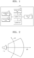
- FIG. 1 is a block diagram illustrating a configuration of an ultrasound diagnosis apparatus 100 according to an embodiment of the present invention.
- the ultrasound diagnosis apparatus 100 includes a receiving unit 110, a calculating unit 120, a visualization unit 130, a display unit 140, may include a controller 160, and an alarm unit 150.
- the components illustrated in FIG. 1 are not indispensable components.
- the ultrasound diagnosis apparatus 100 may include a greater number of components or a less number of components.
- the receiving unit 110 may receive a selection of an attenuation coefficient.
- the selection to the attenuation coefficient may be performed by a user or by the ultrasound diagnosis apparatus 100.
- the attenuation coefficient may be a coefficient representing a degree to which an amplitude is decreased when ultrasound spreads in a medium.
- an attenuation coefficient of water is substantially close to 0, and attenuation coefficients of blood, soft tissues of a human body, and fat are 0.2, 0.5, and 0.6, respectively.
- a user or the ultrasound diagnosis apparatus 100 may select an attenuation coefficient based on characteristics of tissues of an object. For example, when main tissues of an object through which ultrasound passes is a soft tissue, a user may select 0.5 as an attenuation coefficient.
- the receiving unit 110 may obtain information regarding a contrast agent injected into an object.
- the contrast agent is a substance which is used in an imaging process to make it easier to see tissues and blood vessels of the body.
- Examples of the contrast agent of the current embodiment may include an ultrasound contrast agent, micro-bubbles, and the like.
- the contrast agent of the current embodiment may have a size equal to or smaller than a red blood cell.
- the contrast agent may have different vibration characteristics according to manufacturers or products.
- a contrast agent of a manufacturer A shows a linear vibration characteristic at an acoustic pressure of about 50 kPa and a non-linear vibration characteristic at an acoustic pressure of about 100 kPa, and is broken at an acoustic pressure of more than 150 kPa.
- a contrast agent of a manufacturer B may be broken at an acoustic pressure of more than 130 kPa.
- the receiving unit 110 may receive a selection of a first region which is a region of interest (ROI) in an ultrasound diagnosis region of an object. That is, a user may set a certain region of the ultrasound diagnosis region of the displayed object as an ROI.
- ROI region of interest
- the ROI of the current embodiment may be a part in which blood vessels are well-developed.
- the ROI may be a part including a tumor.
- a second region other than the ROI of the ultrasound diagnosis region of the object may be an ultrasound diagnosis region with regard to general tissues where blood vessels are not well-developed.
- the general tissues refer to normal tissues not including a tumor. Examples of the general tissues may include parenchyma and a normal blood vessel.
- the calculating unit 120 may calculate an MI with respect to a depth value in an axis direction in which the ultrasound diagnosis apparatus 100 transmits ultrasound.
- the f awf denotes an acoustic-working frequency of the ultrasound diagnosis apparatus 100.
- the depth value ZMI is obtained according to IEC 62369, which is an international standard of image diagnosis equipment.
- an MI in each operation mode is calculated by the following Formula 2 and Formula 3.
- the calculating unit 120 may calculate MIs with respect to a depth value along a beam direction axis according to the above-defined Formulas.
- the calculating unit 120 may continuously calculate an MI with respect to all depth values, or alternatively, the calculating unit 120 may select some depth values and calculate MIs with respect to only the selected depth values, and the non-calculated MIs may be interpolated using the calculated MIs.
- the calculating unit 120 may calculate acoustic pressure or a thermal index (TI). Methods of calculating acoustic pressure and a TI would have been obvious to one of ordinary skill in the art and thus a detailed description thereof is not provided.
- a TI may include a Soft tissue TI (TIs), a Bone TI (TIb), and a Cranial bone TI (TIc). Accordingly, the calculating unit 120 may individually calculate the TIs, the TIb, and the TIc, or alternatively, may calculate only the TI by selecting a representative TI among the TIs, the TIb, and the TIc.
- TIs Soft tissue TI
- TIb Bone TI
- TIc Cranial bone TI
- the calculating unit 120 may calculate a thermal dose.
- the thermal dose refers to a value obtained by accumulating temperature effects of locations according to time. Accordingly, the calculating unit 120 may accumulate the thermal dose while tracking a varying location by using a motion tracking method.
- the calculating unit 120 may calculate the MI in consideration of the attenuation coefficient selected by a user or the ultrasound diagnosis apparatus 100.
- the visualization unit 130 may generate an MI map in which a relationship between the calculated MI and a depth value is visualized in the form of a graph, which will be described in detail with reference to FIG. 3 .
- a maximum MI value of LDTPs may be visualized based on the following Formula 4.
- I spta ,3, sc STOC MAX active_LDTPs MI LDTP , V LDTP
- MI@ ⁇ x> denotes a value obtained by calculating
- the visualization unit 130 may selectively perform visualization of acoustic pressure and/or visualization of a TI corresponding to a depth value.
- the visualization unit 130 may visualize an MI map, an acoustic pressure map, and a TI map in the form of a two-dimensional or a three-dimensional graph.
- the visualization unit 130 may generate a thermal dose map in which the calculated thermal dose is visualized in the form of a graph.
- the visualization unit 130 may generate a thermal dose map by colors or in the form of a contour or a mesh by accumulating a TI value according to a depth value, a scan line, and time for a predetermined period of time.
- the visualization unit 130 may generate an acoustic pressure map including a threshold value according to a vibration characteristic of a contrast agent injected into an object.
- the threshold value may include at least one of a linear vibration threshold value, a non-linear vibration threshold value, and a breaking vibration threshold value.
- the threshold value may be represented by a line, a region, or color in the acoustic pressure map.
- the visualization unit 130 may represent a linear vibration section, a non-linear vibration section, and a breaking vibration section in green, yellow, and red colors, respectively.
- the display unit 140 may display a result of a map visualized in the form of a graph by the visualization unit 130.
- the display unit 140 may selectively display one or two of three interest index maps, that is, MI, acoustic pressure, TI maps, or may display all the interest index maps.
- the display unit 140 may be configured as a monitor of a general ultrasound diagnosis apparatus or a user interface, as required.
- the display unit 140 may display an interest index, that is, an MI, acoustic pressure, or a TI, together with an ultrasound image on a certain region.
- an interest index that is, an MI, acoustic pressure, or a TI
- an ultrasound image and an interest index may be individually displayed on a screen.
- the display unit 140 may provide an enlarged image with respect to a certain part of the ultrasound image or a certain part of the interest index.
- the display unit 140 may selectively display at least one of a TIs map, a TIb map, and a TIc map. Also, the display unit 140 may selectively display the TI map and the thermal dose map.
- the display unit 140 may display three-dimensional maps with respect to an MI, acoustic pressure, and a TI, or may display at least one of a contour map, a gray map, a mesh map, and a color map.
- the display unit 140 may output an ultrasound image of blood vessel tissues including the contrast agent with respect to the first region, which is an ROI, and may output an ultrasound image of general tissues with respect to the second region.
- the alarm unit 150 may output an alarm signal when the calculated MI or acoustic pressure value exceeds a predetermined value. For example, when the MI is close to 1.9, which is an international standard, the alarm unit 150 may output the alarm signal. In this case, a user may protect an object by controlling a transmission output.
- the alarm unit 150 may output an alarm signal even when the calculated MI or acoustic pressure value is less than a predetermined scope.
- the alarm unit 150 may output the alarm signal.
- a user may increase a transmission output to obtain a high-definition ultrasound image.
- the alarm signal may include at least one of an image signal, a vibration signal, and a voice signal. That is, according to the current embodiment of the present invention, the alarm unit 150 may visually inform that an interest index deviates from a predetermined scope through an image signal including a certain shape, a certain color, an alert message, or the like. Alternatively, the interest index may generate a vibration signal when an interest index deviates from a predetermined scope. Alternatively, the alarm unit 150 may output a voice signal including an alert message, an alert bell, or the like.
- the alarm unit 150 may apply a color map to an interest index map so as to visually show the meaning of an alert clearly according to a degree to which an interest index is close to a predetermined reference value. For example, as the interest index approaches a reference value, the alarm unit 150 may apply a red color to a map, and as interest index deviates the reference value, the alarm unit 150 may apply a blue color to a map.
- the controller 160 may set an acceptable range of an interest index. For example, the controller 160 may set the acceptable range of the interest index based on a user's input or may set an acceptable range automatically according to an international standard. The controller 160 may set the acceptable range of the interest index to be lower than an international standard with respect to a certain object based on a diagnosis breakdown and medical information.
- the controller 160 may control a transmission voltage by controlling an ultrasound output part (not shown). For example, the controller 160 may control the transmission voltage based on an attenuation coefficient selected by a user or the ultrasound diagnosis apparatus 100.
- the controller 160 may control the transmission voltage based on a threshold value according to a vibration characteristic of a contrast agent injected into the object. Since most of the ultrasound contrast agent is broken after a breaking vibration threshold value, the controller 160 may control the transmission voltage so as not to break the contrast agent and to maintain a non-linear vibration characteristic.
- the controller 160 controls a transmission voltage of the first region to a first transmission voltage so as to maintain an MI or an acoustic pressure value in the first region, which is an ROI, within a predetermined threshold range.
- the controller 160 may control a transmission voltage of the first region to the first transmission voltage at which a contrast agent is not broken and a non-linear vibration characteristic is maintained so as to maintain a low MI environment.
- the controller 160 controls a transmission voltage of the second region other than the ROI to be below the first transmission voltage. Since the second region is a region out of a user's interest, image sensitivity of the second region does not need to be high. Accordingly, in order to prevent a contrast agent from being broken, the transmission voltage of the second region may be set to be lower than that of the first region.
- controller 160 may control overall operations of the receiving unit 110, the calculating unit 120, the visualization unit 130, the display unit 140, and the alarm unit 150.
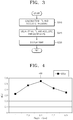
- FIG. 2 is a conceptual diagram illustrating a reference axis for calculating an interest index and displaying a map of the interest index according to an embodiment of the present invention.
- a direction in which ultrasound is transmitted from a transmission transducer 210 of the ultrasound diagnosis apparatus 100 and travels may be an axis of a depth value 230.
- the transmission transducer 210 may be included in a probe.
- the axis of the depth value 230 may start from a boundary surface of an object to be diagnosed using the ultrasound diagnosis apparatus 100 and may correspond to a direction in which the depth value 230 increases inward a soft tissue.
- the probe may transmit an ultrasound beam, which is generated due to transmitted pulse signals that are properly input to be delayed, to an object along a scan line 220.
- the ultrasound diagnosis apparatus 100 may form a two- or three-dimensional map based on interest index values corresponding to the depth value 230 and the scan line 200.
- the probe may be at least one of 1 dimension (1D), 1.5D, and 2D (matrix) probes.
- FIG. 3 is a flowchart illustrating a method of operating the ultrasound diagnosis apparatus 100, according to an embodiment of the present invention.
- the ultrasound diagnosis apparatus 100 may calculate interest indexes, that is, an MI, a TI, and an acoustic pressure, corresponding to depth values in a direction in which ultrasound travels from an ultrasound output part of the transmission transducer 210 (S310).
- the ultrasound diagnosis apparatus 100 may calculate only the MI, and may selectively calculate the acoustic pressure and the TI.
- the MI may be calculated by Formulas 1 to 5 as described above. Also, methods of calculating the acoustic pressure and the TI would have been obvious to one of ordinary skill in the art and thus a detailed description thereof is not provided.
- the ultrasound diagnosis apparatus 100 may select a plurality of depth values and directly calculate the MI by applying the above-defined Formulas 1 to 4 only to the selected depth values, for example, 1, 2.3, 3.1, 4.2, 5.5, and the like.
- the ultrasound diagnosis apparatus 100 may apply a proper interpolation method, for example, a linear interpolation method or an interpolation method according to Formula 5, to the MI corresponding to non-calculated depth values in a direction in which non-calculated ultrasound travels.
- an interpolation method may also be applied to calculate a TI and acoustic pressure.
- a user or the ultrasound diagnosis apparatus 100 may select an attenuation coefficient based on characteristics of tissues of an object.
- the tissues of an object includes blood, soft tissue, and fat that are mixed with one another, and thus, a user or the ultrasound diagnosis apparatus 100 may select an attenuation coefficient by analyzing main components of tissues of the object.
- the ultrasound diagnosis apparatus 100 may calculate an MI in consideration of the selected attenuation coefficient.
- a relationship between the MI and the attenuation coefficient may be obtained with reference to Formula 1.
- Pr.3 denotes a value obtained by calculating acoustic pressure Pr measured in a water tank filled with water at an attenuation rate of 0.3 dB.
- the ultrasound diagnosis apparatus 100 may further increase a transmission voltage, thereby increasing the sensitivity of an ultrasound image.
- the ultrasound diagnosis apparatus 100 may calculate a thermal dose.
- a thermal dose display does not simply display a varying temperature value and displays TI values by colors or in the form of a contour or a mesh by accumulating the TI value according to a depth value, a scan line, and time for a predetermined period of time, and thus, changes in temperature of an object due to ultrasound may be effectively seen.
- the ultrasound diagnosis apparatus 100 may generate an interest index map in which a relationship between a depth value and the calculated interest index (that is, the MI, the acoustic pressure, the TI, and the thermal dose) that is visualized in the form of a graph (S320).
- the MI may vary according to the depth value.
- the ultrasound diagnosis apparatus 100 since the ultrasound diagnosis apparatus 100 uses a focus beam, the MI may have a maximum value at a depth value being focused. Also, even in an acoustic pressure map, a similar result to the MI map illustrated in FIG. 4 may be obtained. Although a TI map may have a similar shape to the MI map or the acoustic pressure map, a TI may have a maximum value at a depth value lower than the depth value being focused.
- the ultrasound diagnosis apparatus 100 may generate an interest index map as a 1D, 2D, or 3D map.
- the ultrasound diagnosis apparatus 100 may generate the interest index map as a 2D map by calculating interest indexes corresponding to the depth value 230 and the scan line 220.
- the ultrasound diagnosis apparatus 100 may generate a 3D map by representing the interest indexes corresponding to the depth value 230 and the scan line 220 sterically in the form of a mesh.
- the ultrasound diagnosis apparatus 100 may represent the interest index map that varies according to time (frame) without being fixed during ultrasound scanning. That is, the ultrasound diagnosis apparatus 100 may generate a 3D map by calculating interest indexes according to the depth value 230, the scan line 220, and time.
- the ultrasound diagnosis apparatus 100 may represent interest indexes of three directions of axial (a depth value), lateral (a scan line), and elevation in the form of a 3D map.
- the ultrasound diagnosis apparatus 100 may represent an interest index map as various maps, for example, a contour map, a gray map, a mesh map, a color map, or the like. For example, as illustrated in FIG. 5A , the ultrasound diagnosis apparatus 100 may generate a 2D map as a gray scale with respect to the depth value 230 and the scan line 220. Also, as illustrated in FIG. 5B , the ultrasound diagnosis apparatus 100 may generate a 2D map in the form of a contour.
- the ultrasound diagnosis apparatus 100 may display the interest index maps, that is, the MI, acoustic pressure, and TI maps, by using the display unit 140 (S330).
- the display unit 140 may display TIs, TIb, and TIc maps as one TI map.
- the display unit 140 may designate different colors to the TIs, TIb, and TIc maps or represent lines with different thicknesses for easy distinction.
- the display unit 140 may display a certain TI map that is arbitrarily selected by a user among the TIs, TIb, and TIc maps.
- the ultrasound diagnosis apparatus 100 may not easily determine whether an object being diagnosed is a soft tissue, a bone, or a cranial bone, and thus, the maximum map among the TIs, TIb, and TIc maps may be selected as a representative TI map and displayed.
- the ultrasound diagnosis apparatus 100 may represent an interest index map in various ways, for example, in the form of a 1D, 2D, or 3D map. Accordingly, a user may easily see a degree to which interest indexes are distributed, and may visually check whether each interest index exceeds an acceptable reference value based on map information and may also check regions where the interest indexes exceed the acceptable reference value.
- the ultrasound diagnosis apparatus 100 may combine two or more maps among a contour map, a gray map, a mesh map, and a color map that are generated with respect to an interest index and may display the combined map.
- the ultrasound diagnosis apparatus 100 may display a threshold value according to a vibration characteristic of a contrast agent together with an acoustic pressure map.
- the ultrasound diagnosis apparatus 100 may display the threshold value of the contrast agent on the acoustic pressure map according to a depth value.
- the contrast agent linearly vibrates between 0 and a linear vibration threshold value and non-linearly vibrates between the linear vibration threshold value and a non-linear vibration threshold value.
- the contrast agent non-linearly vibrates after the non-linear vibration threshold value, and at the same time, a rate at which the contrast agent is broken starts to be increased after the non-linear vibration threshold value, and thus, most of the contrast agent is broken after a breaking vibration threshold value.
- a user may control a transmission voltage so as not to break the contrast agent and to maintain a non-linear vibration characteristic by checking the threshold value according to the vibration characteristic of the contrast agent provided by the ultrasound diagnosis apparatus 100.
- the threshold value may be represented by colors or lines.
- FIG. 7 is a view illustrating an MI map in an ROI according to an embodiment of the present invention.
- a user may set a first region 710, which is an ROI, in an ultrasound diagnosis image.
- a first region 710 which is an ROI
- the user may set a part including the tumor as the first region 710, which is the ROI, in order to determine whether the tumor is a benign or malignant tumor.
- the ultrasound diagnosis apparatus 100 may differently control MIs or acoustic pressures of the first region 710 and a second region 720 other than the ROI in the ultrasound diagnosis image.
- the ultrasound diagnosis apparatus 100 may obtain an ultrasound image from the first region 710 by stimulating and vibrating the used contrast agent, and may obtain an ultrasound image from the second region 720 by using an MI or acoustic pressure having a degree at which the contrast agent is rarely broken. That is, the ultrasound diagnosis apparatus 100 may set a transmission voltage of the second region 720 to be lower than that of the first region 710.
- an ultrasound image may be obtained from the second region 720 other than the first region 710, which is an ROI, by using an MI or acoustic pressure having a degree at which the contrast agent is rarely broken, and thus, a rate at which the contrast agent is broken may be significantly decreased.
- FIG. 7A illustrates an MI of an ROI according to a depth value. Since the ultrasound diagnosis apparatus 100 uses a focus beam, when the focus beam is focused on the ROI, an MI in the first region 710, which is the ROI, may be a maximum.
- FIG. 7B illustrates an MI of an ROI according to a scan line.
- an MI of a scan line in the first region 710 may be higher that in the second region 720.
- ultrasound image sensitivity in the ROI may be strategically increased.
- the ultrasound diagnosis apparatus 100 may output an ultrasound image of blood vessel tissues including a contrast agent with respect to the first region 710 and may output an ultrasound image of general tissues with respect to the second region 720.
- Embodiments of the present invention include a computer-readable recording medium including program commands for executing operations implemented through various computers.
- the computer-readable recording medium can store program commands, data files, data structures, or combinations thereof.
- the program commands recorded in the computer-readable recording medium may be specially designed and configured for the present invention or be known to those skilled in the field of computer software.
- Examples of a computer-readable recording medium include magnetic media such as hard disks, floppy disks, and magnetic tapes, optical media such as CD-ROMs and DVDs, magneto-optical media such as floptical disks, or hardware devices such as ROMs, RAMs, and flash memories, which are specially configured to store and execute program commands.
- Examples of the program commands include a machine language code created by a compiler and a high-level language code executable by a computer using an interpreter and the like.
- the above-described hardware apparatus may be configured to operate as at least one software module in order to perform operations of the present invention.
- an interest index for example, an MI, acoustic pressure, a TI, and the like, according to depths of a ultrasound diagnosis part may be provided to a user or a health professional in the form of a map, and thus, the user or the health professional may visually check whether the interest index exceeds an international acceptable reference value and may check regions where the interest index exceeds the acceptable reference value.
- a user may control a transmission output so as to maintain an international acceptable reference value of an interest index and to maximize image quality.
- an ultrasound diagnosis apparatus using a contrast agent or micro-bubbles information capable of performing a precision adjustment regarding using of the contrast agent or the micro-bubbles may be provided to a user. Accordingly, the user may adjust acoustic pressure so as to maximize the quality of an ultrasound image without breaking the micro-bubbles.
Landscapes
- Health & Medical Sciences (AREA)
- Engineering & Computer Science (AREA)
- Life Sciences & Earth Sciences (AREA)
- Medical Informatics (AREA)
- Public Health (AREA)
- Physics & Mathematics (AREA)
- General Health & Medical Sciences (AREA)
- Biomedical Technology (AREA)
- Pathology (AREA)
- Molecular Biology (AREA)
- Surgery (AREA)
- Veterinary Medicine (AREA)
- Animal Behavior & Ethology (AREA)
- Heart & Thoracic Surgery (AREA)
- Radiology & Medical Imaging (AREA)
- Nuclear Medicine, Radiotherapy & Molecular Imaging (AREA)
- Biophysics (AREA)
- Remote Sensing (AREA)
- Radar, Positioning & Navigation (AREA)
- General Physics & Mathematics (AREA)
- Computer Networks & Wireless Communication (AREA)
- Databases & Information Systems (AREA)
- Data Mining & Analysis (AREA)
- Primary Health Care (AREA)
- Epidemiology (AREA)
- Physiology (AREA)
- Computer Vision & Pattern Recognition (AREA)
- Ultra Sonic Daignosis Equipment (AREA)
Claims (9)
- Appareil de diagnostic par ultrasons (100) comprenant :une unité de calcul (120) pour calculer un indice mécanique (MI) correspondant à une valeur de profondeur (230) dans une direction dans laquelle les ultrasons se propagent depuis une partie de sortie ultrasonique d'un transducteur de transmission, un indice thermique (TI) correspondant à la valeur de profondeur et une ligne de balayage, et une dose thermique en accumulant le TI en fonction de la valeur de profondeur, de la ligne de balayage et du temps;une unité de visualisation (130) pour générer une carte MI dans laquelle une relation entre le MI calculé et la valeur de profondeur (230) est visualisée sous la forme d'un graphique, une carte TI tridimensionnelle en représentant le TI calculé correspondant à la valeur de la profondeur et la ligne de balayage stériquement sous forme de maillage, et une carte de dose thermique basée sur le TI accumulé par au moins une forme de couleurs, un contour et un maillage ;une unité d'affichage (140) pour afficher au moins un élément sélectionné parmi un groupe comprenant la carte MI, la carte TI, et la carte de dose thermique ;une unité de réception (110) pour recevoir une entrée utilisateur pour une sélection d'un coefficient d'atténuation particulier ; etune commande (160) pour contrôler une tension de transmission sur la base du coefficient d'atténuation sélectionné par l'entrée utilisateur,dans lequel l'unité de calcul (120) est en outre configurée pour calculer le MI en considération du coefficient d'atténuation sélectionné,dans lequel l'unité de réception (110) est en outre configurée pour recevoir une sélection d'une première région (710) qui est une région d'intérêt (ROI) dans une région de diagnostic ultrasonore de l'objet, etdans lequel la commande (160) est en outre configurée pour contrôler une tension de transmission de la première région à une première tension de transmission afin de maintenir la valeur de MI ou de pression acoustique dans la première région (710) dans une plage de seuil prédéterminée, et pour contrôler une tension de transmission d'une seconde région (720) de sorte qu'une tension de transmission de la seconde région (720) autre que la ROI dans la région de diagnostic ultrasonore de l'objet soit inférieure à la première tension de transmission.
- Appareil de diagnostic par ultrasons (100) selon la revendication 1, dans lequel l'unité de calcul (120) est en outre configurée pour calculer
une valeur de pression acoustique correspondant à des valeurs de profondeur (230) dans une direction dans laquelle les ultrasons se propagent depuis la partie de sortie ultrasonique du transducteur de transmission ; l'unité de visualisation (130) est en outre configurée pour générer une carte de pression acoustique dans laquelle une relation entre la valeur de pression acoustique calculée et la valeur de profondeur (230) est visualisée sous la forme d'un graphique ; et l'unité d'affichage (140) est configurée pour afficher sélectivement la carte MI ou la carte de pression acoustique. - Appareil de diagnostic par ultrasons (100) selon la revendication 2, comprenant en outre une unité d'alarme (150) pour émettre un signal d'alarme lorsque le MI calculé ou la valeur de pression acoustique calculé dépasse une plage prédéterminée.
- Appareil de diagnostic par ultrasons (100) selon la revendication 1, dans lequel la carte MI est une carte bidimensionnelle ou tridimensionnelle.
- Appareil de diagnostic par ultrasons (100) selon la revendication 1, dans lequel le coefficient d'atténuation est sélectionné en fonction des caractéristiques des tissus d'un objet.
- Appareil de diagnostic par ultrasons (100) selon la revendication 2, dans lequel l'unité de réception (110) est en outre configurée pour obtenir des informations concernant un agent de contraste injecté dans un objet, et l'unité de visualisation (130) est en outre configurée pour générer une carte de pression acoustique comprenant une valeur de seuil due à une caractéristique de vibration de l'agent de contraste injecté dans l'objet.
- Appareil de diagnostic par ultrasons (100) selon la revendication 6, dans lequel la valeur de seuil comprend au moins un élément choisi dans le groupe consistant en une valeur de seuil de vibration linéaire, une valeur de seuil de vibration non-linéaire, et une valeur de seuil de vibration de rupture.
- Appareil de diagnostic par ultrasons (100) selon la revendication 6, dans lequel la commande (160) est en outre configurée pour contrôler une tension de transmission sur la base d'une valeur de seuil due à une caractéristique de vibration de l'agent de contraste injecté dans l'objet.
- Appareil de diagnostic par ultrasons (100) selon la revendication 1, dans lequel l'unité d'affichage (140) est en outre configurée pour émettre une image ultrasonique de tissus de vaisseaux sanguins comprenant un agent de contraste par rapport à la première région (710), et une image ultrasonique de tissus généraux par rapport à la seconde région (720).
Priority Applications (1)
| Application Number | Priority Date | Filing Date | Title |
|---|---|---|---|
| EP11195229.7A EP2468191B1 (fr) | 2010-12-22 | 2011-12-22 | Appareil de diagnostic par ultrasons pour la fourniture d'une carte d'indices d'intérêt |
Applications Claiming Priority (4)
| Application Number | Priority Date | Filing Date | Title |
|---|---|---|---|
| KR20100132633 | 2010-12-22 | ||
| EP11163085 | 2011-04-19 | ||
| KR1020110125211A KR101313222B1 (ko) | 2010-12-22 | 2011-11-28 | 관심 지표의 맵을 제공하는 초음파 장치의 동작 방법 및 상기 방법을 이용한 초음파 진단 장치 |
| EP11195229.7A EP2468191B1 (fr) | 2010-12-22 | 2011-12-22 | Appareil de diagnostic par ultrasons pour la fourniture d'une carte d'indices d'intérêt |
Publications (2)
| Publication Number | Publication Date |
|---|---|
| EP2468191A1 EP2468191A1 (fr) | 2012-06-27 |
| EP2468191B1 true EP2468191B1 (fr) | 2019-01-30 |
Family
ID=45346376
Family Applications (1)
| Application Number | Title | Priority Date | Filing Date |
|---|---|---|---|
| EP11195229.7A Active EP2468191B1 (fr) | 2010-12-22 | 2011-12-22 | Appareil de diagnostic par ultrasons pour la fourniture d'une carte d'indices d'intérêt |
Country Status (1)
| Country | Link |
|---|---|
| EP (1) | EP2468191B1 (fr) |
Cited By (1)
| Publication number | Priority date | Publication date | Assignee | Title |
|---|---|---|---|---|
| US20250272845A1 (en) * | 2022-11-04 | 2025-08-28 | Exact Therapeutics As | Method for reconfiguring ultrasound |
Families Citing this family (4)
| Publication number | Priority date | Publication date | Assignee | Title |
|---|---|---|---|---|
| US10667790B2 (en) | 2012-03-26 | 2020-06-02 | Teratech Corporation | Tablet ultrasound system |
| US9877699B2 (en) | 2012-03-26 | 2018-01-30 | Teratech Corporation | Tablet ultrasound system |
| SI3049117T1 (sl) | 2013-09-27 | 2022-11-30 | Exact Therapeutics As | Dostava zdravil, posredovana z ultrazvokom |
| CN113509209B (zh) * | 2021-08-11 | 2024-04-16 | 首都医科大学附属北京同仁医院 | 一种眼科超声成像方法及装置 |
Citations (2)
| Publication number | Priority date | Publication date | Assignee | Title |
|---|---|---|---|---|
| US20090036772A1 (en) * | 2006-01-26 | 2009-02-05 | The University Of Toledo | High frame rate imaging system |
| JP2009142474A (ja) * | 2007-12-14 | 2009-07-02 | Ge Medical Systems Global Technology Co Llc | 超音波撮像装置 |
Family Cites Families (3)
| Publication number | Priority date | Publication date | Assignee | Title |
|---|---|---|---|---|
| US5509413A (en) * | 1993-08-11 | 1996-04-23 | Kabushiki Kaisha Toshiba | Ultrasonic diagnostic apparatus |
| US6413218B1 (en) * | 2000-02-10 | 2002-07-02 | Acuson Corporation | Medical diagnostic ultrasound imaging system and method for determining an acoustic output parameter of a transmitted ultrasonic beam |
| US20060030779A1 (en) * | 2004-08-09 | 2006-02-09 | Siemens Medical Solutions Usa, Inc. | Intensity level control for contrast agent imaging |
-
2011
- 2011-12-22 EP EP11195229.7A patent/EP2468191B1/fr active Active
Patent Citations (2)
| Publication number | Priority date | Publication date | Assignee | Title |
|---|---|---|---|---|
| US20090036772A1 (en) * | 2006-01-26 | 2009-02-05 | The University Of Toledo | High frame rate imaging system |
| JP2009142474A (ja) * | 2007-12-14 | 2009-07-02 | Ge Medical Systems Global Technology Co Llc | 超音波撮像装置 |
Cited By (2)
| Publication number | Priority date | Publication date | Assignee | Title |
|---|---|---|---|---|
| US20250272845A1 (en) * | 2022-11-04 | 2025-08-28 | Exact Therapeutics As | Method for reconfiguring ultrasound |
| US12511755B2 (en) * | 2022-11-04 | 2025-12-30 | Exact Therapeutics As | Method for reconfiguring ultrasound |
Also Published As
| Publication number | Publication date |
|---|---|
| EP2468191A1 (fr) | 2012-06-27 |
Similar Documents
| Publication | Publication Date | Title |
|---|---|---|
| US9629610B2 (en) | Method of operating ultrasound diagnosis apparatus for providing map of interest index and ultrasound diagnosis apparatus using the method | |
| KR101313222B1 (ko) | 관심 지표의 맵을 제공하는 초음파 장치의 동작 방법 및 상기 방법을 이용한 초음파 진단 장치 | |
| EP3530195B1 (fr) | Appareil d'analyse et procédé d'analyse | |
| EP2371290B1 (fr) | Appareil de diagnostic à ultrasons, appareil de traitement d'images à ultrasons et appareil d'imagerie pour le diagnostic médical | |
| JP5735718B2 (ja) | 超音波診断装置、及び弾性評価方法 | |
| KR102268668B1 (ko) | 대상체에 대한 복수의 상이한 영상들을 디스플레이하는 방법 및 장치 | |
| EP2030570A2 (fr) | Appareil de diagnostic à ultrasons, appareil de traitement d'images et procédé de traitement d'images | |
| EP2394580A1 (fr) | Appareil de diagnostic à ultrasons, appareil de traitement d'images à ultrasons et appareil d'imagerie pour le diagnostic médical | |
| JP7237079B2 (ja) | マルチパラメトリック組織の剛性の定量化 | |
| EP2468191B1 (fr) | Appareil de diagnostic par ultrasons pour la fourniture d'une carte d'indices d'intérêt | |
| US20150379700A1 (en) | Ultrasound image displaying apparatus and method for displaying ultrasound image | |
| CN102387747A (zh) | 超声波诊断装置以及血流动态的分布像的构成方法 | |
| JP5213019B2 (ja) | 超音波撮像装置 | |
| US12089995B2 (en) | Ultrasound medical imaging with optimized speed of sound based on fat fraction | |
| JP7330705B2 (ja) | 画像解析装置 | |
| US12274582B2 (en) | Ultrasound elastography method and system | |
| EP2052686A1 (fr) | Appareil de diagnostic ultrasonique et son programme de contrôle | |
| JP2011110211A (ja) | 医用画像表示装置及び血流動態の分布像構成方法 | |
| EP3364881B1 (fr) | Appareil d'imagerie par ultrasons et son procédé de commande | |
| US20180049720A1 (en) | Ultrasound beamforming system and method | |
| EP2599442B1 (fr) | Procédé et appareil pour la correction d'images ultrasonores au moyen d'une carte à index d'intérêt | |
| US20050075566A1 (en) | Ultrasonice diagnosing apparatus | |
| JP2005111258A (ja) | 超音波診断装置 | |
| JP5534649B2 (ja) | 超音波診断装置 | |
| JPH0751268A (ja) | 超音波診断装置 |
Legal Events
| Date | Code | Title | Description |
|---|---|---|---|
| AK | Designated contracting states |
Kind code of ref document: A1 Designated state(s): AL AT BE BG CH CY CZ DE DK EE ES FI FR GB GR HR HU IE IS IT LI LT LU LV MC MK MT NL NO PL PT RO RS SE SI SK SM TR |
|
| AX | Request for extension of the european patent |
Extension state: BA ME |
|
| PUAI | Public reference made under article 153(3) epc to a published international application that has entered the european phase |
Free format text: ORIGINAL CODE: 0009012 |
|
| 17P | Request for examination filed |
Effective date: 20121219 |
|
| 17Q | First examination report despatched |
Effective date: 20160915 |
|
| STAA | Information on the status of an ep patent application or granted ep patent |
Free format text: STATUS: EXAMINATION IS IN PROGRESS |
|
| GRAP | Despatch of communication of intention to grant a patent |
Free format text: ORIGINAL CODE: EPIDOSNIGR1 |
|
| STAA | Information on the status of an ep patent application or granted ep patent |
Free format text: STATUS: GRANT OF PATENT IS INTENDED |
|
| INTG | Intention to grant announced |
Effective date: 20180608 |
|
| GRAS | Grant fee paid |
Free format text: ORIGINAL CODE: EPIDOSNIGR3 |
|
| GRAA | (expected) grant |
Free format text: ORIGINAL CODE: 0009210 |
|
| STAA | Information on the status of an ep patent application or granted ep patent |
Free format text: STATUS: THE PATENT HAS BEEN GRANTED |
|
| AK | Designated contracting states |
Kind code of ref document: B1 Designated state(s): AL AT BE BG CH CY CZ DE DK EE ES FI FR GB GR HR HU IE IS IT LI LT LU LV MC MK MT NL NO PL PT RO RS SE SI SK SM TR |
|
| REG | Reference to a national code |
Ref country code: GB Ref legal event code: FG4D |
|
| REG | Reference to a national code |
Ref country code: CH Ref legal event code: EP |
|
| REG | Reference to a national code |
Ref country code: AT Ref legal event code: REF Ref document number: 1092597 Country of ref document: AT Kind code of ref document: T Effective date: 20190215 |
|
| REG | Reference to a national code |
Ref country code: IE Ref legal event code: FG4D |
|
| REG | Reference to a national code |
Ref country code: DE Ref legal event code: R096 Ref document number: 602011056069 Country of ref document: DE |
|
| REG | Reference to a national code |
Ref country code: NL Ref legal event code: FP |
|
| REG | Reference to a national code |
Ref country code: LT Ref legal event code: MG4D |
|
| PG25 | Lapsed in a contracting state [announced via postgrant information from national office to epo] |
Ref country code: PL Free format text: LAPSE BECAUSE OF FAILURE TO SUBMIT A TRANSLATION OF THE DESCRIPTION OR TO PAY THE FEE WITHIN THE PRESCRIBED TIME-LIMIT Effective date: 20190130 Ref country code: NO Free format text: LAPSE BECAUSE OF FAILURE TO SUBMIT A TRANSLATION OF THE DESCRIPTION OR TO PAY THE FEE WITHIN THE PRESCRIBED TIME-LIMIT Effective date: 20190430 Ref country code: ES Free format text: LAPSE BECAUSE OF FAILURE TO SUBMIT A TRANSLATION OF THE DESCRIPTION OR TO PAY THE FEE WITHIN THE PRESCRIBED TIME-LIMIT Effective date: 20190130 Ref country code: PT Free format text: LAPSE BECAUSE OF FAILURE TO SUBMIT A TRANSLATION OF THE DESCRIPTION OR TO PAY THE FEE WITHIN THE PRESCRIBED TIME-LIMIT Effective date: 20190530 Ref country code: LT Free format text: LAPSE BECAUSE OF FAILURE TO SUBMIT A TRANSLATION OF THE DESCRIPTION OR TO PAY THE FEE WITHIN THE PRESCRIBED TIME-LIMIT Effective date: 20190130 Ref country code: SE Free format text: LAPSE BECAUSE OF FAILURE TO SUBMIT A TRANSLATION OF THE DESCRIPTION OR TO PAY THE FEE WITHIN THE PRESCRIBED TIME-LIMIT Effective date: 20190130 Ref country code: FI Free format text: LAPSE BECAUSE OF FAILURE TO SUBMIT A TRANSLATION OF THE DESCRIPTION OR TO PAY THE FEE WITHIN THE PRESCRIBED TIME-LIMIT Effective date: 20190130 |
|
| REG | Reference to a national code |
Ref country code: AT Ref legal event code: MK05 Ref document number: 1092597 Country of ref document: AT Kind code of ref document: T Effective date: 20190130 |
|
| PG25 | Lapsed in a contracting state [announced via postgrant information from national office to epo] |
Ref country code: BG Free format text: LAPSE BECAUSE OF FAILURE TO SUBMIT A TRANSLATION OF THE DESCRIPTION OR TO PAY THE FEE WITHIN THE PRESCRIBED TIME-LIMIT Effective date: 20190430 Ref country code: HR Free format text: LAPSE BECAUSE OF FAILURE TO SUBMIT A TRANSLATION OF THE DESCRIPTION OR TO PAY THE FEE WITHIN THE PRESCRIBED TIME-LIMIT Effective date: 20190130 Ref country code: GR Free format text: LAPSE BECAUSE OF FAILURE TO SUBMIT A TRANSLATION OF THE DESCRIPTION OR TO PAY THE FEE WITHIN THE PRESCRIBED TIME-LIMIT Effective date: 20190501 Ref country code: IS Free format text: LAPSE BECAUSE OF FAILURE TO SUBMIT A TRANSLATION OF THE DESCRIPTION OR TO PAY THE FEE WITHIN THE PRESCRIBED TIME-LIMIT Effective date: 20190530 Ref country code: LV Free format text: LAPSE BECAUSE OF FAILURE TO SUBMIT A TRANSLATION OF THE DESCRIPTION OR TO PAY THE FEE WITHIN THE PRESCRIBED TIME-LIMIT Effective date: 20190130 Ref country code: RS Free format text: LAPSE BECAUSE OF FAILURE TO SUBMIT A TRANSLATION OF THE DESCRIPTION OR TO PAY THE FEE WITHIN THE PRESCRIBED TIME-LIMIT Effective date: 20190130 |
|
| PG25 | Lapsed in a contracting state [announced via postgrant information from national office to epo] |
Ref country code: DK Free format text: LAPSE BECAUSE OF FAILURE TO SUBMIT A TRANSLATION OF THE DESCRIPTION OR TO PAY THE FEE WITHIN THE PRESCRIBED TIME-LIMIT Effective date: 20190130 Ref country code: SK Free format text: LAPSE BECAUSE OF FAILURE TO SUBMIT A TRANSLATION OF THE DESCRIPTION OR TO PAY THE FEE WITHIN THE PRESCRIBED TIME-LIMIT Effective date: 20190130 Ref country code: AL Free format text: LAPSE BECAUSE OF FAILURE TO SUBMIT A TRANSLATION OF THE DESCRIPTION OR TO PAY THE FEE WITHIN THE PRESCRIBED TIME-LIMIT Effective date: 20190130 Ref country code: CZ Free format text: LAPSE BECAUSE OF FAILURE TO SUBMIT A TRANSLATION OF THE DESCRIPTION OR TO PAY THE FEE WITHIN THE PRESCRIBED TIME-LIMIT Effective date: 20190130 Ref country code: RO Free format text: LAPSE BECAUSE OF FAILURE TO SUBMIT A TRANSLATION OF THE DESCRIPTION OR TO PAY THE FEE WITHIN THE PRESCRIBED TIME-LIMIT Effective date: 20190130 Ref country code: EE Free format text: LAPSE BECAUSE OF FAILURE TO SUBMIT A TRANSLATION OF THE DESCRIPTION OR TO PAY THE FEE WITHIN THE PRESCRIBED TIME-LIMIT Effective date: 20190130 |
|
| REG | Reference to a national code |
Ref country code: DE Ref legal event code: R097 Ref document number: 602011056069 Country of ref document: DE |
|
| PG25 | Lapsed in a contracting state [announced via postgrant information from national office to epo] |
Ref country code: SM Free format text: LAPSE BECAUSE OF FAILURE TO SUBMIT A TRANSLATION OF THE DESCRIPTION OR TO PAY THE FEE WITHIN THE PRESCRIBED TIME-LIMIT Effective date: 20190130 |
|
| PLBE | No opposition filed within time limit |
Free format text: ORIGINAL CODE: 0009261 |
|
| STAA | Information on the status of an ep patent application or granted ep patent |
Free format text: STATUS: NO OPPOSITION FILED WITHIN TIME LIMIT |
|
| PG25 | Lapsed in a contracting state [announced via postgrant information from national office to epo] |
Ref country code: AT Free format text: LAPSE BECAUSE OF FAILURE TO SUBMIT A TRANSLATION OF THE DESCRIPTION OR TO PAY THE FEE WITHIN THE PRESCRIBED TIME-LIMIT Effective date: 20190130 |
|
| 26N | No opposition filed |
Effective date: 20191031 |
|
| PGFP | Annual fee paid to national office [announced via postgrant information from national office to epo] |
Ref country code: NL Payment date: 20191106 Year of fee payment: 9 |
|
| PG25 | Lapsed in a contracting state [announced via postgrant information from national office to epo] |
Ref country code: SI Free format text: LAPSE BECAUSE OF FAILURE TO SUBMIT A TRANSLATION OF THE DESCRIPTION OR TO PAY THE FEE WITHIN THE PRESCRIBED TIME-LIMIT Effective date: 20190130 |
|
| PG25 | Lapsed in a contracting state [announced via postgrant information from national office to epo] |
Ref country code: TR Free format text: LAPSE BECAUSE OF FAILURE TO SUBMIT A TRANSLATION OF THE DESCRIPTION OR TO PAY THE FEE WITHIN THE PRESCRIBED TIME-LIMIT Effective date: 20190130 |
|
| REG | Reference to a national code |
Ref country code: CH Ref legal event code: PL |
|
| REG | Reference to a national code |
Ref country code: BE Ref legal event code: MM Effective date: 20191231 |
|
| PG25 | Lapsed in a contracting state [announced via postgrant information from national office to epo] |
Ref country code: MC Free format text: LAPSE BECAUSE OF FAILURE TO SUBMIT A TRANSLATION OF THE DESCRIPTION OR TO PAY THE FEE WITHIN THE PRESCRIBED TIME-LIMIT Effective date: 20190130 |
|
| GBPC | Gb: european patent ceased through non-payment of renewal fee |
Effective date: 20191222 |
|
| PG25 | Lapsed in a contracting state [announced via postgrant information from national office to epo] |
Ref country code: GB Free format text: LAPSE BECAUSE OF NON-PAYMENT OF DUE FEES Effective date: 20191222 Ref country code: LU Free format text: LAPSE BECAUSE OF NON-PAYMENT OF DUE FEES Effective date: 20191222 Ref country code: IE Free format text: LAPSE BECAUSE OF NON-PAYMENT OF DUE FEES Effective date: 20191222 |
|
| PG25 | Lapsed in a contracting state [announced via postgrant information from national office to epo] |
Ref country code: LI Free format text: LAPSE BECAUSE OF NON-PAYMENT OF DUE FEES Effective date: 20191231 Ref country code: BE Free format text: LAPSE BECAUSE OF NON-PAYMENT OF DUE FEES Effective date: 20191231 Ref country code: CH Free format text: LAPSE BECAUSE OF NON-PAYMENT OF DUE FEES Effective date: 20191231 |
|
| PG25 | Lapsed in a contracting state [announced via postgrant information from national office to epo] |
Ref country code: CY Free format text: LAPSE BECAUSE OF FAILURE TO SUBMIT A TRANSLATION OF THE DESCRIPTION OR TO PAY THE FEE WITHIN THE PRESCRIBED TIME-LIMIT Effective date: 20190130 |
|
| PG25 | Lapsed in a contracting state [announced via postgrant information from national office to epo] |
Ref country code: HU Free format text: LAPSE BECAUSE OF FAILURE TO SUBMIT A TRANSLATION OF THE DESCRIPTION OR TO PAY THE FEE WITHIN THE PRESCRIBED TIME-LIMIT; INVALID AB INITIO Effective date: 20111222 Ref country code: MT Free format text: LAPSE BECAUSE OF FAILURE TO SUBMIT A TRANSLATION OF THE DESCRIPTION OR TO PAY THE FEE WITHIN THE PRESCRIBED TIME-LIMIT Effective date: 20190130 |
|
| REG | Reference to a national code |
Ref country code: NL Ref legal event code: MM Effective date: 20210101 |
|
| PG25 | Lapsed in a contracting state [announced via postgrant information from national office to epo] |
Ref country code: NL Free format text: LAPSE BECAUSE OF NON-PAYMENT OF DUE FEES Effective date: 20210101 |
|
| PG25 | Lapsed in a contracting state [announced via postgrant information from national office to epo] |
Ref country code: MK Free format text: LAPSE BECAUSE OF FAILURE TO SUBMIT A TRANSLATION OF THE DESCRIPTION OR TO PAY THE FEE WITHIN THE PRESCRIBED TIME-LIMIT Effective date: 20190130 |
|
| PGFP | Annual fee paid to national office [announced via postgrant information from national office to epo] |
Ref country code: DE Payment date: 20251105 Year of fee payment: 15 |
|
| PGFP | Annual fee paid to national office [announced via postgrant information from national office to epo] |
Ref country code: IT Payment date: 20251106 Year of fee payment: 15 |
|
| PGFP | Annual fee paid to national office [announced via postgrant information from national office to epo] |
Ref country code: FR Payment date: 20251111 Year of fee payment: 15 |