EP2468367B1 - Butée d'une fixation de ski - Google Patents
Butée d'une fixation de ski Download PDFInfo
- Publication number
- EP2468367B1 EP2468367B1 EP12158326.4A EP12158326A EP2468367B1 EP 2468367 B1 EP2468367 B1 EP 2468367B1 EP 12158326 A EP12158326 A EP 12158326A EP 2468367 B1 EP2468367 B1 EP 2468367B1
- Authority
- EP
- European Patent Office
- Prior art keywords
- sole
- ski
- housing
- boot
- unit according
- Prior art date
- Legal status (The legal status is an assumption and is not a legal conclusion. Google has not performed a legal analysis and makes no representation as to the accuracy of the status listed.)
- Revoked
Links
Images


Classifications
-
- A—HUMAN NECESSITIES
- A63—SPORTS; GAMES; AMUSEMENTS
- A63C—SKATES; SKIS; ROLLER SKATES; DESIGN OR LAYOUT OF COURTS, RINKS OR THE LIKE
- A63C9/00—Ski bindings
- A63C9/08—Ski bindings yieldable or self-releasing in the event of an accident, i.e. safety bindings
- A63C9/085—Ski bindings yieldable or self-releasing in the event of an accident, i.e. safety bindings with sole hold-downs, e.g. swingable
- A63C9/08507—Ski bindings yieldable or self-releasing in the event of an accident, i.e. safety bindings with sole hold-downs, e.g. swingable with a plurality of mobile jaws
- A63C9/08521—Ski bindings yieldable or self-releasing in the event of an accident, i.e. safety bindings with sole hold-downs, e.g. swingable with a plurality of mobile jaws pivoting about a vertical axis, e.g. side release
-
- A—HUMAN NECESSITIES
- A63—SPORTS; GAMES; AMUSEMENTS
- A63C—SKATES; SKIS; ROLLER SKATES; DESIGN OR LAYOUT OF COURTS, RINKS OR THE LIKE
- A63C9/00—Ski bindings
- A63C9/08—Ski bindings yieldable or self-releasing in the event of an accident, i.e. safety bindings
- A63C9/085—Ski bindings yieldable or self-releasing in the event of an accident, i.e. safety bindings with sole hold-downs, e.g. swingable
- A63C9/08535—Ski bindings yieldable or self-releasing in the event of an accident, i.e. safety bindings with sole hold-downs, e.g. swingable with a mobile body or base or single jaw
- A63C9/08542—Ski bindings yieldable or self-releasing in the event of an accident, i.e. safety bindings with sole hold-downs, e.g. swingable with a mobile body or base or single jaw pivoting about a transversal axis
-
- A—HUMAN NECESSITIES
- A63—SPORTS; GAMES; AMUSEMENTS
- A63C—SKATES; SKIS; ROLLER SKATES; DESIGN OR LAYOUT OF COURTS, RINKS OR THE LIKE
- A63C9/00—Ski bindings
- A63C9/08—Ski bindings yieldable or self-releasing in the event of an accident, i.e. safety bindings
- A63C9/085—Ski bindings yieldable or self-releasing in the event of an accident, i.e. safety bindings with sole hold-downs, e.g. swingable
- A63C9/08557—Details of the release mechanism
- A63C9/08585—Details of the release mechanism using transverse biasing element
-
- A—HUMAN NECESSITIES
- A63—SPORTS; GAMES; AMUSEMENTS
- A63C—SKATES; SKIS; ROLLER SKATES; DESIGN OR LAYOUT OF COURTS, RINKS OR THE LIKE
- A63C9/00—Ski bindings
- A63C9/001—Anti-friction devices
-
- A—HUMAN NECESSITIES
- A63—SPORTS; GAMES; AMUSEMENTS
- A63C—SKATES; SKIS; ROLLER SKATES; DESIGN OR LAYOUT OF COURTS, RINKS OR THE LIKE
- A63C9/00—Ski bindings
- A63C9/08—Ski bindings yieldable or self-releasing in the event of an accident, i.e. safety bindings
- A63C9/085—Ski bindings yieldable or self-releasing in the event of an accident, i.e. safety bindings with sole hold-downs, e.g. swingable
- A63C9/08592—Structure or making
Definitions
- the invention relates to a shoe holder assembly of a ski binding, with on a housing to housing-side vertical axes pivotable sole holders, which overlap an edge region of a housing-side end of an inserted into the shoe holder assembly ski boot sole from side to side and up and interact with a arranged in the housing spring arrangement, which tensions the sole holders in their chucking positions and allows a triggering of the ski boot sole in the sideways direction against a triggering resistance.
- the sole holder on a support member which is resiliently supported in the direction of the ski vertical axis and in the ski direction.
- the support member is supported in Skiquerides such that it receives an increasing range of motion in the vertical direction in sideways movements.
- the end of the ski boot sole used in the shoe holder assembly thus receives an additional mobility in the vertical direction during a sideways movement, so that the ski boot sole can be triggered both in the upward and in the sideways direction.
- the object of the invention is therefore to ensure a further increase in safety for the skier in a shoe holder assembly of the type specified.
- a two-piece, plate-like base 1 is arranged, the rear part in the ski longitudinal direction 1 '' formed on its upper side bearing blocks 2 with bearing eyes 3, the purpose of which is explained below.
- the front in the ski longitudinal direction part 1 'of the base part 1 has two spaced apart in the transverse direction Skischerlegizen forked projections 4, which can be positively inserted into corresponding recesses in the part 1'', such that the parts 1' and 1 '' with each other without relative mobility are positively connected transversely to the extensions 4.
- the part 1 'of the base part is fastened on the top of the ski with screws 5, which passes through the provided vertical holes on the extensions 4. Then the part 1 '' in the longitudinal direction of the extensions 4 is pushed onto the same and fastened with screws 6 on the ski.
- the parts 1 'and 1''of the base part 1 are formed such that the part 1' on the ski-holding screws 5 directly under the bearing blocks 2 and the bearing eyes 3 of the part 1 '' are arranged, if the Base part 1 is mounted on the ski. Since the part 1 '' cooperates positively with the extensions 4 and is immovably held transversely to the longitudinal axes of the extensions 4, forces acting on the bearing eyes 3 in the upward direction are ablated directly on the screws 5 and thus on the ski.
- the screws 6 serve essentially only to prevent a separation of the parts 1 'and 1''from each other.
- Shoe holder unit shown has a housing 7 with an inner body 7 'and a shell-like outer body 7''.
- the bearing lugs 8 'of the inner body 7' take a position axially between the bearing eyes 3 of the part 1 '' of the base part 1, while the bearing eyes 8 "of the outer body 7 '' are each provided on the opposite outer sides of the bearing eyes 3.
- the housing 7 in the Fig. 4 and 5 seeks to pivot clockwise while a trained on the bottom of the inner body 7 'stage 13 against shoulders on the bearing blocks 2 of the part 1''of the base part 1 biases so that the housing 7 in a through the step 13 and the shoulders of the bearing blocks 2 predetermined end position is brought.
- the abutments 10 and 11 each have the shape of a downwardly or upwardly open cup with conical inner circumference, which widens conically towards the opening of the respective cup.
- a tube spring 14 is arranged with the taper of the inner peripheries of the cup-shaped abutment 10 and 11 barrel-shaped outer circumference, wherein the tube spring 14 each protrudes slightly into the cup-shaped abutment 10 and 11.
- This tube spring 14 acts as a relatively stiff compression spring when the housing 7 in the Fig. 4 and 5 applied with a torque counterclockwise becomes. The housing 7 can therefore tilt counterclockwise only when exposed to a large torque.
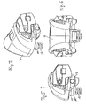
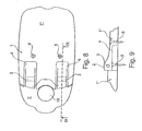
- pivotable sole holder 16 On the side edges of the housing 7 15 pivotable sole holder 16 are arranged around lateral housing high axes. These sole holders 16 serve, on the one hand, to engage with abutment rollers 18 arranged on them by means of axes of rotation 17 on lateral edges of a sole of a ski boot in order to lock the sole in the sideways direction of the ski. On the other hand, the sole holders 16 are intended to overlap the upper side of the sole edge with overlapping surfaces 19 extended in the transverse direction of the sole holders 16 from above, in order to lock the respective ski boot sole vertically on the ski upper side. As in particular from Fig.
- the overlapping surfaces 19 have the shape of a downwardly directed blunt wedge with a wedge tip extending in the transverse direction of the respective sole holder 16.
- the sole holders 16 abut against a line-shaped contact zone extending in the sole transverse direction, which is located in the immediate vicinity of the vertical contact zone of the contact roller 18 arranged on the respective sole holder 16.
- the sole holders 16 are formed with respect to their vertical pivot axes 15 as a double arm, wherein the housing-side arm the cross section of an inner body 7 'of the housing 7, the inner body 7' transversely overlapping channel 20 overlaps.
- piston 21 are slidably disposed, between which a helical compression spring 22 is clamped.
- the helical compression spring 22 on the one hand at the bottom of in Fig. 1 the left piston 21 and on the other hand supported on an abutment 23 adjustably arranged in the right piston 21.
- This plate-like abutment 23 has a threaded bore into which the external thread of an adjusting screw 24 is screwed, which in turn with an annular disc-shaped flange on the bottom of in Fig. 1 right piston 21 is supported and has a for a screwing tool through a hole in the piston head accessible Phillips head, so that the abutment disc 23 can be moved by rotation of the adjusting screw 24 by changing the voltage of the helical compression spring 22.
- the assembly of the shoe holder assembly described above on a ski can be carried out as follows: First, the front part 'of the base part 1 is mounted on the ski. Thereafter, the rear part 1 '' of the base part 1 parallel to Skioberseite be pushed onto the extensions 4 of the part 1 'and secured by means of screws 6 on the ski. Now, through the sole holder 16, the piston 21 and the helical compression spring 22, etc.
- the tilting axis 9 can be inserted into the aforementioned bearing eyes , wherein prior to assembly of the tilting axis 9, the helical compression spring 12 is inserted into the tube spring 14 and is inserted together with the tube spring 14 between the abutments 10 and 11.
- the shoe holder assembly according to the invention is ready to use mounted on the ski, it must only be set to the desired release force on the adjusting screw 24.
- the shoe-holder assembly operates (in a generally known manner) as follows:
- the ski boot is inserted with a sole end, typically with the front sole end between the sole holders 16, such that the tops of the lateral sole edges are overlapped by the overlapping surfaces 19 of the sole holders 16.
- the ski boot or its sole is locked with the other sole end to an associated heel-side sole holder unit or the like on the ski. If now strong forces act in the sideways direction on the inserted between the sole holders 16 sole end, the rear in the direction of force sole holder 16 opens under pivoting about its pivot axis 15, wherein the respective sole holder 16 associated piston 21 is displaced against the force of the helical compression spring 22.
- the sole can be released vertically upwards by the housing 7 pivots counter to the force of the helical compression spring 12 and in particular the tube spring 14 counterclockwise.
- the tops of the sole edges are no longer overlapped by the overlapping surfaces 19, and the ski boot is released in the upward direction of the ski.
- this vertical release is facilitated by the upward sloping upwardly inclined surfaces 19 ', where the front sole end can slip upwards out of the binding.
- the aforementioned pivoting of the housing 7 is also initiated when the ski boot sole should be urged parallel to the ski upper side in the ski longitudinal direction with great force against the housing 7. This can be done, for example, in an "untypical" backward fall of a skier.
- two-part base part 1 may also be a one-piece base part 1 may be provided, in particular a retractable in a ski in the ski longitudinal direction rail system base part which is positively and / or non-positively fixable on the rail system.
Landscapes
- Footwear And Its Accessory, Manufacturing Method And Apparatuses (AREA)
Claims (15)
- Ensemble de maintien de chaussure d'une fixation de ski, comportant des éléments de maintien de semelle (16) pouvant pivoter sur un boîtier (7) autour d'axes verticaux (15) côté boîtier, lesquels éléments de maintien de semelle entourent ou chevauchent latéralement et à partir du haut une zone de rebord d'une semelle de chaussure de ski placée dans l'ensemble et coopèrent avec un agencement à ressort (22) agencé dans le boîtier (7), lequel agencement à ressort serre les éléments de maintien de semelle (16) dans leurs positions de serrage et permet une libération de la semelle de chaussure de ski dans une direction latérale à l'encontre d'une résistance à la libération,
dans lequel les éléments de maintien de semelle (16) chevauchent respectivement à partir du haut la partie supérieure du bord de semelle avec des surfaces de chevauchement (19) s'étendant dans une direction transversale des éléments de maintien de semelle, afin de bloquer la semelle de chaussure de ski respective verticalement sur le côté supérieur du ski,
caractérisé en ce que :a) les surfaces de chevauchement (19) sont inclinées dans la direction transversale du ski, les surfaces de chevauchement (19) montant jusqu'au centre du ski,b) ou les surfaces de chevauchement (19) forment une surface inclinée (19') dirigée vers le haut jusqu'à l'extrémité libre des éléments de maintien de semelle (16). - Ensemble de maintien de chaussure selon la revendication 1, caractérisé en ce que les éléments de maintien de semelle (16) peuvent être placés sur des bords latéraux de la semelle de chaussure de ski avec des galets d'application (18) agencés sur eux au moyen d'axes de rotation (17) afin de bloquer la semelle dans la direction latérale.
- Ensemble de maintien de chaussure selon l'une des revendications précédentes, caractérisé en ce que les éléments de maintien de semelle (16) rappellent le bord de semelle latéralement et à partir du haut sur des zones de contact linéaires, dont les axes longitudinaux sont étendus dans ou directement adjacents à un plan transversal vertical.
- Ensemble de maintien de chaussure selon l'une des revendications précédentes, caractérisé en ce que les surfaces de chevauchement (19) sont inclinées dans la direction transversale du ski, dans lequel les surfaces de chevauchement (19) ont la forme d'un cône tronqué dirigé vers le bas avec une pointe de cône s'étendant dans la direction transversale de l'élément de maintien de semelle (16) respectif.
- Ensemble de maintien de chaussure selon l'une des revendications précédentes, caractérisé en ce que les éléments de maintien de semelle (16) sont configurés sous la forme d'un levier à deux bras par rapport à leurs axes verticaux (15), dans lequel le bras côté boîtier chevauche la section transversale d'un canal traversant le boîtier (7) dans la direction transversale et agencé dans le boîtier (7), dans lequel des pistons (21) sont agencés de manière mobile à l'intérieur du canal, pistons entre lesquels est serré un ressort de pression de vis (22).
- Ensemble de maintien de chaussure selon l'une des revendications précédentes, caractérisé en ce que le boîtier (7) est agencé sur une plaque de support agencée ou pouvant être fixée sur un ski de manière à pouvoir pivoter pour des manoeuvres de ski.
- Ensemble de maintien de chaussure selon l'une des revendications précédentes, caractérisé en ce que le boîtier peut pivoter autour d'un axe transversal (9) qui est agencé dans ou au-dessous d'un plan de contact de la semelle de chaussure de ski à proximité immédiate du bord transversal côté boîtier de la semelle de chaussure de ski placée dans l'ensemble.
- Ensemble de maintien de chaussure selon la revendication précédente, caractérisé en ce que le boîtier (7) peut pivoter autour de l'axe transversal (9) à l'encontre d'une force élastique (12, 14).
- Ensemble de maintien de chaussure selon l'une des revendications précédentes, caractérisé en ce que le boîtier (7) est articulé autour d'un axe transversal (9) de manière à pouvoir pivoter sur une pièce de base (1) agencée ou pouvant être fixée sur la partie supérieure du ski ou de la plaque de support, laquelle pièce de base est directement assemblée au ski ou à la plaque de support sous l'axe transversal (9) ou est fixée sur le ski ou la plaque de support avec des vis (5).
- Ensemble de maintien de chaussure selon la revendication précédente, caractérisé en ce que la pièce de base (1) comporte une partie avant (1') avec au moins une extension (4) s'étendant dans une direction longitudinale de la pièce de base, sur laquelle la partie arrière (1") de la pièce de base (1) peut être repoussée par complémentarité de formes et avec un jeu pratiquement nul transversalement à la direction longitudinale de l'extension, et en ce que des paliers d'appui (2) agencés sur la partie arrière (1") sont positionnés directement sur des vis de fixation (5) de la partie avant (1') pour supporter le boîtier (7) de manière pivotante lorsque la partie arrière (1") est en position repoussée.
- Ensemble de maintien de chaussure selon l'une des revendications précédentes, caractérisé en ce que le boîtier (7) est supporté sur la pièce de base (1) de manière élastique à une certaine distance radiale de l'axe transversal (9).
- Ensemble de maintien de chaussure selon la revendication précédente, caractérisé en ce que le support élastique comporte un ressort de pression de vis (12) qui est serré entre une butée côté boîtier et une butée côté pièce de base (10, 11), dans lequel le tube-ressort (14) est de préférence constitué d'une matière plastique élastiquement déformable.
- Ensemble de maintien de chaussure selon l'une des deux revendications précédentes, caractérisé en ce que le support élastique comporte un tube-ressort (14) qui est agencé entre un palier côté boîtier et un palier côté pièce de base (10, 11).
- Ensemble de maintien de chaussure selon l'une des deux revendications précédentes, caractérisé en ce que le ressort de pression de vis (12) est placé dans un tube-ressort (14) coaxial à celui-ci, dans lequel le tube-ressort (14) est de préférence constitué d'une matière plastique élastiquement déformable.
- Ensemble de maintien de chaussure selon l'une des deux revendications précédentes, caractérisé en ce que le tube-ressort (14) présente une périphérie extérieure convexe en forme de barillet et fait ainsi saillie vers l'intérieur axialement dans des butées en forme de cuvette (10, 11), dont les parois circonférentielles intérieures incluent les tubes-ressorts (14) pratiquement sans jeu radial et présentent une conicité adaptée à la forme en barillet.
Applications Claiming Priority (2)
| Application Number | Priority Date | Filing Date | Title |
|---|---|---|---|
| DE102008050884A DE102008050884A1 (de) | 2008-10-09 | 2008-10-09 | Schuhhalteraggregat einer Skibindung |
| EP09171434A EP2174695B1 (fr) | 2008-10-09 | 2009-09-28 | Butée d'une fixation de ski dont le boitier est articulé autour d'un axe transversal |
Related Parent Applications (2)
| Application Number | Title | Priority Date | Filing Date |
|---|---|---|---|
| EP09171434A Division EP2174695B1 (fr) | 2008-10-09 | 2009-09-28 | Butée d'une fixation de ski dont le boitier est articulé autour d'un axe transversal |
| EP09171434.5 Division | 2009-09-28 |
Publications (2)
| Publication Number | Publication Date |
|---|---|
| EP2468367A1 EP2468367A1 (fr) | 2012-06-27 |
| EP2468367B1 true EP2468367B1 (fr) | 2014-09-17 |
Family
ID=41478513
Family Applications (2)
| Application Number | Title | Priority Date | Filing Date |
|---|---|---|---|
| EP12158326.4A Revoked EP2468367B1 (fr) | 2008-10-09 | 2009-09-28 | Butée d'une fixation de ski |
| EP09171434A Active EP2174695B1 (fr) | 2008-10-09 | 2009-09-28 | Butée d'une fixation de ski dont le boitier est articulé autour d'un axe transversal |
Family Applications After (1)
| Application Number | Title | Priority Date | Filing Date |
|---|---|---|---|
| EP09171434A Active EP2174695B1 (fr) | 2008-10-09 | 2009-09-28 | Butée d'une fixation de ski dont le boitier est articulé autour d'un axe transversal |
Country Status (3)
| Country | Link |
|---|---|
| EP (2) | EP2468367B1 (fr) |
| AT (1) | ATE548088T1 (fr) |
| DE (1) | DE102008050884A1 (fr) |
Families Citing this family (6)
| Publication number | Priority date | Publication date | Assignee | Title |
|---|---|---|---|---|
| EP2329864B1 (fr) * | 2009-09-30 | 2014-02-19 | MARKER Deutschland GmbH | Fixation de ski dotée d'une structure en cage |
| FR2966747B1 (fr) * | 2010-10-29 | 2013-01-11 | Salomon Sas | Fixation de securite pour la pratique du ski. |
| EP2574378B1 (fr) | 2011-09-19 | 2016-09-14 | Salomon S.A.S. | Fixation d'une chaussure sur une planche de glisse |
| AT515560B1 (de) * | 2014-03-28 | 2016-02-15 | Tyrolia Technology Gmbh | Vorderbacken |
| DE102018125546A1 (de) * | 2018-10-15 | 2020-04-16 | Marker Deutschland Gmbh | Vorderbacken |
| FR3107652B1 (fr) | 2020-02-27 | 2022-01-28 | Salomon Sas | Butée avant de fixation pour planche de glisse |
Family Cites Families (8)
| Publication number | Priority date | Publication date | Assignee | Title |
|---|---|---|---|---|
| AT343522B (de) * | 1975-12-24 | 1978-06-12 | Hausleithner Andreas | Kabellose sicherheitsschibindung |
| US4298213A (en) * | 1978-01-23 | 1981-11-03 | Vereinigte Baubeschlagfabriken Gretsch & Co. Gmbh | Ski safety binding of the diagonal release type |
| DE3129965A1 (de) * | 1981-07-29 | 1983-02-17 | Geze Gmbh, 7250 Leonberg | Sicherheitsskibindung |
| DE3905445A1 (de) | 1989-02-22 | 1990-08-23 | Marker Deutschland Gmbh | Vorderbacken fuer sicherheitsskibindungen |
| FR2712202B1 (fr) * | 1993-11-10 | 1995-12-29 | Salomon Sa | Elément dde fixation de ski alpin. |
| AT402796B (de) * | 1995-02-01 | 1997-08-25 | Fritschi Apparatebau | Schibindung |
| CH693129A5 (de) * | 1998-11-16 | 2003-03-14 | Look Fixations Sa | Sicherheitsskibindung. |
| DE102006039989B4 (de) | 2006-08-25 | 2015-10-08 | Marker Deutschland Gmbh | Schuhhalteraggregat einer Skibindung |
-
2008
- 2008-10-09 DE DE102008050884A patent/DE102008050884A1/de not_active Withdrawn
-
2009
- 2009-09-28 EP EP12158326.4A patent/EP2468367B1/fr not_active Revoked
- 2009-09-28 AT AT09171434T patent/ATE548088T1/de active
- 2009-09-28 EP EP09171434A patent/EP2174695B1/fr active Active
Also Published As
| Publication number | Publication date |
|---|---|
| DE102008050884A1 (de) | 2010-04-15 |
| EP2174695A1 (fr) | 2010-04-14 |
| EP2174695B1 (fr) | 2012-03-07 |
| EP2468367A1 (fr) | 2012-06-27 |
| ATE548088T1 (de) | 2012-03-15 |
Similar Documents
| Publication | Publication Date | Title |
|---|---|---|
| EP2468367B1 (fr) | Butée d'une fixation de ski | |
| EP3702005B1 (fr) | Talonnière | |
| EP2611673B1 (fr) | Colonne de direction pour un véhicule automobile | |
| DE3310739C2 (fr) | ||
| EP3345659B1 (fr) | Talonnière automatique pour une fixation de ski | |
| DE2227500A1 (de) | Skibindung | |
| EP1428559B1 (fr) | Fixation déclenchable | |
| DE2221105B2 (de) | Sicherheits-Skibindung | |
| DE3031611A1 (de) | Backen einer skibindung | |
| EP1342874A2 (fr) | Charnière de meuble avec dispositif de réglage | |
| EP3117881B1 (fr) | Machoire avant d'une fixation de ski de surete | |
| EP0061590B1 (fr) | Frein de ski | |
| DE69002220T2 (de) | Sicherheitsbindung mit einer Platte. | |
| AT502930B1 (de) | Verbindungsvorrichtung zwischen einem schuh und einem brettartigen sportgerät, insbesondere schibindung | |
| DE3151222C2 (de) | Vorderbacken für eine Sicherheits-Skibindung | |
| EP0408855B1 (fr) | Mâchoire avant | |
| EP2851108B1 (fr) | Mâchoire avant pour une fixation de ski | |
| DE4010923A1 (de) | Sicherheitsskibindung mit einer verschwenkbaren sohlenplatte | |
| AT519786B1 (de) | Sicherheitsskibindung | |
| DE19725252C2 (de) | Laufsportartikel, insbesondere Inline-Skate | |
| DE102015105190B4 (de) | Seitenauslöse- und Andruckfedereinrichtung | |
| EP4417276B1 (fr) | Mâchoire avant et fixation de sécurité de ski dotée d'une mâchoire avant | |
| DE3123432C1 (de) | Sicherheitsskibindung | |
| EP0438659B1 (fr) | Fixation déclenchable | |
| DE3403113A1 (de) | Sicherheitsbindung fuer ski zum halten mit seitlicher ausloesemoeglichkeit eines endes eines skistiefels gegenueber einem ski |
Legal Events
| Date | Code | Title | Description |
|---|---|---|---|
| 17P | Request for examination filed |
Effective date: 20120306 |
|
| AC | Divisional application: reference to earlier application |
Ref document number: 2174695 Country of ref document: EP Kind code of ref document: P |
|
| AK | Designated contracting states |
Kind code of ref document: A1 Designated state(s): AT BE BG CH CY CZ DE DK EE ES FI FR GB GR HR HU IE IS IT LI LT LU LV MC MK MT NL NO PL PT RO SE SI SK SM TR |
|
| PUAI | Public reference made under article 153(3) epc to a published international application that has entered the european phase |
Free format text: ORIGINAL CODE: 0009012 |
|
| GRAP | Despatch of communication of intention to grant a patent |
Free format text: ORIGINAL CODE: EPIDOSNIGR1 |
|
| RIC1 | Information provided on ipc code assigned before grant |
Ipc: A63C 9/085 20120101ALI20140430BHEP Ipc: A63C 9/00 20120101ALI20140430BHEP Ipc: A63C 9/08 20120101AFI20140430BHEP |
|
| INTG | Intention to grant announced |
Effective date: 20140527 |
|
| GRAS | Grant fee paid |
Free format text: ORIGINAL CODE: EPIDOSNIGR3 |
|
| GRAA | (expected) grant |
Free format text: ORIGINAL CODE: 0009210 |
|
| AC | Divisional application: reference to earlier application |
Ref document number: 2174695 Country of ref document: EP Kind code of ref document: P |
|
| AK | Designated contracting states |
Kind code of ref document: B1 Designated state(s): AT BE BG CH CY CZ DE DK EE ES FI FR GB GR HR HU IE IS IT LI LT LU LV MC MK MT NL NO PL PT RO SE SI SK SM TR |
|
| REG | Reference to a national code |
Ref country code: GB Ref legal event code: FG4D Free format text: NOT ENGLISH |
|
| REG | Reference to a national code |
Ref country code: CH Ref legal event code: NV Representative=s name: RIEDERER HASLER AND PARTNER PATENTANWAELTE AG, LI Ref country code: CH Ref legal event code: EP |
|
| REG | Reference to a national code |
Ref country code: IE Ref legal event code: FG4D Free format text: LANGUAGE OF EP DOCUMENT: GERMAN |
|
| REG | Reference to a national code |
Ref country code: AT Ref legal event code: REF Ref document number: 687405 Country of ref document: AT Kind code of ref document: T Effective date: 20141015 |
|
| REG | Reference to a national code |
Ref country code: DE Ref legal event code: R096 Ref document number: 502009009993 Country of ref document: DE Effective date: 20141030 |
|
| PG25 | Lapsed in a contracting state [announced via postgrant information from national office to epo] |
Ref country code: NO Free format text: LAPSE BECAUSE OF FAILURE TO SUBMIT A TRANSLATION OF THE DESCRIPTION OR TO PAY THE FEE WITHIN THE PRESCRIBED TIME-LIMIT Effective date: 20141217 Ref country code: GR Free format text: LAPSE BECAUSE OF FAILURE TO SUBMIT A TRANSLATION OF THE DESCRIPTION OR TO PAY THE FEE WITHIN THE PRESCRIBED TIME-LIMIT Effective date: 20141218 Ref country code: LT Free format text: LAPSE BECAUSE OF FAILURE TO SUBMIT A TRANSLATION OF THE DESCRIPTION OR TO PAY THE FEE WITHIN THE PRESCRIBED TIME-LIMIT Effective date: 20140917 Ref country code: FI Free format text: LAPSE BECAUSE OF FAILURE TO SUBMIT A TRANSLATION OF THE DESCRIPTION OR TO PAY THE FEE WITHIN THE PRESCRIBED TIME-LIMIT Effective date: 20140917 Ref country code: SE Free format text: LAPSE BECAUSE OF FAILURE TO SUBMIT A TRANSLATION OF THE DESCRIPTION OR TO PAY THE FEE WITHIN THE PRESCRIBED TIME-LIMIT Effective date: 20140917 |
|
| REG | Reference to a national code |
Ref country code: NL Ref legal event code: VDEP Effective date: 20140917 |
|
| REG | Reference to a national code |
Ref country code: LT Ref legal event code: MG4D |
|
| PG25 | Lapsed in a contracting state [announced via postgrant information from national office to epo] |
Ref country code: CY Free format text: LAPSE BECAUSE OF FAILURE TO SUBMIT A TRANSLATION OF THE DESCRIPTION OR TO PAY THE FEE WITHIN THE PRESCRIBED TIME-LIMIT Effective date: 20140917 Ref country code: HR Free format text: LAPSE BECAUSE OF FAILURE TO SUBMIT A TRANSLATION OF THE DESCRIPTION OR TO PAY THE FEE WITHIN THE PRESCRIBED TIME-LIMIT Effective date: 20140917 Ref country code: LV Free format text: LAPSE BECAUSE OF FAILURE TO SUBMIT A TRANSLATION OF THE DESCRIPTION OR TO PAY THE FEE WITHIN THE PRESCRIBED TIME-LIMIT Effective date: 20140917 |
|
| PG25 | Lapsed in a contracting state [announced via postgrant information from national office to epo] |
Ref country code: NL Free format text: LAPSE BECAUSE OF FAILURE TO SUBMIT A TRANSLATION OF THE DESCRIPTION OR TO PAY THE FEE WITHIN THE PRESCRIBED TIME-LIMIT Effective date: 20140917 |
|
| PG25 | Lapsed in a contracting state [announced via postgrant information from national office to epo] |
Ref country code: SK Free format text: LAPSE BECAUSE OF FAILURE TO SUBMIT A TRANSLATION OF THE DESCRIPTION OR TO PAY THE FEE WITHIN THE PRESCRIBED TIME-LIMIT Effective date: 20140917 Ref country code: RO Free format text: LAPSE BECAUSE OF FAILURE TO SUBMIT A TRANSLATION OF THE DESCRIPTION OR TO PAY THE FEE WITHIN THE PRESCRIBED TIME-LIMIT Effective date: 20140917 Ref country code: ES Free format text: LAPSE BECAUSE OF FAILURE TO SUBMIT A TRANSLATION OF THE DESCRIPTION OR TO PAY THE FEE WITHIN THE PRESCRIBED TIME-LIMIT Effective date: 20140917 Ref country code: IS Free format text: LAPSE BECAUSE OF FAILURE TO SUBMIT A TRANSLATION OF THE DESCRIPTION OR TO PAY THE FEE WITHIN THE PRESCRIBED TIME-LIMIT Effective date: 20150117 Ref country code: CZ Free format text: LAPSE BECAUSE OF FAILURE TO SUBMIT A TRANSLATION OF THE DESCRIPTION OR TO PAY THE FEE WITHIN THE PRESCRIBED TIME-LIMIT Effective date: 20140917 Ref country code: EE Free format text: LAPSE BECAUSE OF FAILURE TO SUBMIT A TRANSLATION OF THE DESCRIPTION OR TO PAY THE FEE WITHIN THE PRESCRIBED TIME-LIMIT Effective date: 20140917 Ref country code: PT Free format text: LAPSE BECAUSE OF FAILURE TO SUBMIT A TRANSLATION OF THE DESCRIPTION OR TO PAY THE FEE WITHIN THE PRESCRIBED TIME-LIMIT Effective date: 20150119 |
|
| PG25 | Lapsed in a contracting state [announced via postgrant information from national office to epo] |
Ref country code: PL Free format text: LAPSE BECAUSE OF FAILURE TO SUBMIT A TRANSLATION OF THE DESCRIPTION OR TO PAY THE FEE WITHIN THE PRESCRIBED TIME-LIMIT Effective date: 20140917 |
|
| REG | Reference to a national code |
Ref country code: DE Ref legal event code: R026 Ref document number: 502009009993 Country of ref document: DE |
|
| PLBI | Opposition filed |
Free format text: ORIGINAL CODE: 0009260 |
|
| PG25 | Lapsed in a contracting state [announced via postgrant information from national office to epo] |
Ref country code: MC Free format text: LAPSE BECAUSE OF FAILURE TO SUBMIT A TRANSLATION OF THE DESCRIPTION OR TO PAY THE FEE WITHIN THE PRESCRIBED TIME-LIMIT Effective date: 20140917 Ref country code: BE Free format text: LAPSE BECAUSE OF NON-PAYMENT OF DUE FEES Effective date: 20140930 |
|
| REG | Reference to a national code |
Ref country code: IE Ref legal event code: MM4A |
|
| 26 | Opposition filed |
Opponent name: TYROLIA TECHNOLOGY GMBH Effective date: 20150615 |
|
| PLAX | Notice of opposition and request to file observation + time limit sent |
Free format text: ORIGINAL CODE: EPIDOSNOBS2 |
|
| PG25 | Lapsed in a contracting state [announced via postgrant information from national office to epo] |
Ref country code: DK Free format text: LAPSE BECAUSE OF FAILURE TO SUBMIT A TRANSLATION OF THE DESCRIPTION OR TO PAY THE FEE WITHIN THE PRESCRIBED TIME-LIMIT Effective date: 20140917 |
|
| GBPC | Gb: european patent ceased through non-payment of renewal fee |
Effective date: 20141217 |
|
| PG25 | Lapsed in a contracting state [announced via postgrant information from national office to epo] |
Ref country code: IE Free format text: LAPSE BECAUSE OF NON-PAYMENT OF DUE FEES Effective date: 20140928 Ref country code: IT Free format text: LAPSE BECAUSE OF FAILURE TO SUBMIT A TRANSLATION OF THE DESCRIPTION OR TO PAY THE FEE WITHIN THE PRESCRIBED TIME-LIMIT Effective date: 20140917 |
|
| REG | Reference to a national code |
Ref country code: FR Ref legal event code: PLFP Year of fee payment: 7 |
|
| PG25 | Lapsed in a contracting state [announced via postgrant information from national office to epo] |
Ref country code: GB Free format text: LAPSE BECAUSE OF NON-PAYMENT OF DUE FEES Effective date: 20141217 |
|
| PLBB | Reply of patent proprietor to notice(s) of opposition received |
Free format text: ORIGINAL CODE: EPIDOSNOBS3 |
|
| PG25 | Lapsed in a contracting state [announced via postgrant information from national office to epo] |
Ref country code: SI Free format text: LAPSE BECAUSE OF FAILURE TO SUBMIT A TRANSLATION OF THE DESCRIPTION OR TO PAY THE FEE WITHIN THE PRESCRIBED TIME-LIMIT Effective date: 20140917 |
|
| PLAB | Opposition data, opponent's data or that of the opponent's representative modified |
Free format text: ORIGINAL CODE: 0009299OPPO |
|
| R26 | Opposition filed (corrected) |
Opponent name: TYROLIA TECHNOLOGY GMBH Effective date: 20150615 |
|
| PG25 | Lapsed in a contracting state [announced via postgrant information from national office to epo] |
Ref country code: SM Free format text: LAPSE BECAUSE OF FAILURE TO SUBMIT A TRANSLATION OF THE DESCRIPTION OR TO PAY THE FEE WITHIN THE PRESCRIBED TIME-LIMIT Effective date: 20140917 |
|
| PG25 | Lapsed in a contracting state [announced via postgrant information from national office to epo] |
Ref country code: MT Free format text: LAPSE BECAUSE OF FAILURE TO SUBMIT A TRANSLATION OF THE DESCRIPTION OR TO PAY THE FEE WITHIN THE PRESCRIBED TIME-LIMIT Effective date: 20140917 Ref country code: BG Free format text: LAPSE BECAUSE OF FAILURE TO SUBMIT A TRANSLATION OF THE DESCRIPTION OR TO PAY THE FEE WITHIN THE PRESCRIBED TIME-LIMIT Effective date: 20140917 |
|
| PG25 | Lapsed in a contracting state [announced via postgrant information from national office to epo] |
Ref country code: TR Free format text: LAPSE BECAUSE OF FAILURE TO SUBMIT A TRANSLATION OF THE DESCRIPTION OR TO PAY THE FEE WITHIN THE PRESCRIBED TIME-LIMIT Effective date: 20140917 Ref country code: HU Free format text: LAPSE BECAUSE OF FAILURE TO SUBMIT A TRANSLATION OF THE DESCRIPTION OR TO PAY THE FEE WITHIN THE PRESCRIBED TIME-LIMIT; INVALID AB INITIO Effective date: 20090928 Ref country code: LU Free format text: LAPSE BECAUSE OF NON-PAYMENT OF DUE FEES Effective date: 20140928 |
|
| REG | Reference to a national code |
Ref country code: FR Ref legal event code: PLFP Year of fee payment: 8 |
|
| REG | Reference to a national code |
Ref country code: DE Ref legal event code: R064 Ref document number: 502009009993 Country of ref document: DE Ref country code: DE Ref legal event code: R103 Ref document number: 502009009993 Country of ref document: DE |
|
| PGFP | Annual fee paid to national office [announced via postgrant information from national office to epo] |
Ref country code: CH Payment date: 20160926 Year of fee payment: 8 |
|
| RDAF | Communication despatched that patent is revoked |
Free format text: ORIGINAL CODE: EPIDOSNREV1 |
|
| STAA | Information on the status of an ep patent application or granted ep patent |
Free format text: STATUS: THE PATENT HAS BEEN GRANTED |
|
| PGFP | Annual fee paid to national office [announced via postgrant information from national office to epo] |
Ref country code: FR Payment date: 20160923 Year of fee payment: 8 Ref country code: AT Payment date: 20160921 Year of fee payment: 8 |
|
| PGFP | Annual fee paid to national office [announced via postgrant information from national office to epo] |
Ref country code: DE Payment date: 20160930 Year of fee payment: 8 |
|
| RDAG | Patent revoked |
Free format text: ORIGINAL CODE: 0009271 |
|
| REG | Reference to a national code |
Ref country code: CH Ref legal event code: PLX |
|
| 27W | Patent revoked |
Effective date: 20161024 |
|
| PG25 | Lapsed in a contracting state [announced via postgrant information from national office to epo] |
Ref country code: LI Free format text: LAPSE BECAUSE OF THE APPLICANT RENOUNCES Effective date: 20140917 Ref country code: CH Free format text: LAPSE BECAUSE OF THE APPLICANT RENOUNCES Effective date: 20140917 |
|
| REG | Reference to a national code |
Ref country code: AT Ref legal event code: MA03 Ref document number: 687405 Country of ref document: AT Kind code of ref document: T Effective date: 20161024 |
|
| STAA | Information on the status of an ep patent application or granted ep patent |
Free format text: STATUS: PATENT REVOKED |