EP2468376A1 - Distributeur de liquide pour colonne avec garnissage - Google Patents
Distributeur de liquide pour colonne avec garnissage Download PDFInfo
- Publication number
- EP2468376A1 EP2468376A1 EP11009611A EP11009611A EP2468376A1 EP 2468376 A1 EP2468376 A1 EP 2468376A1 EP 11009611 A EP11009611 A EP 11009611A EP 11009611 A EP11009611 A EP 11009611A EP 2468376 A1 EP2468376 A1 EP 2468376A1
- Authority
- EP
- European Patent Office
- Prior art keywords
- liquid
- distribution
- column
- sieve
- distributed
- Prior art date
- Legal status (The legal status is an assumption and is not a legal conclusion. Google has not performed a legal analysis and makes no representation as to the accuracy of the status listed.)
- Withdrawn
Links
Images




Classifications
-
- B—PERFORMING OPERATIONS; TRANSPORTING
- B01—PHYSICAL OR CHEMICAL PROCESSES OR APPARATUS IN GENERAL
- B01D—SEPARATION
- B01D3/00—Distillation or related exchange processes in which liquids are contacted with gaseous media, e.g. stripping
- B01D3/14—Fractional distillation or use of a fractionation or rectification column
- B01D3/26—Fractionating columns in which vapour and liquid flow past each other, or in which the fluid is sprayed into the vapour, or in which a two-phase mixture is passed in one direction
-
- B—PERFORMING OPERATIONS; TRANSPORTING
- B01—PHYSICAL OR CHEMICAL PROCESSES OR APPARATUS IN GENERAL
- B01D—SEPARATION
- B01D3/00—Distillation or related exchange processes in which liquids are contacted with gaseous media, e.g. stripping
- B01D3/008—Liquid distribution
-
- B—PERFORMING OPERATIONS; TRANSPORTING
- B01—PHYSICAL OR CHEMICAL PROCESSES OR APPARATUS IN GENERAL
- B01D—SEPARATION
- B01D3/00—Distillation or related exchange processes in which liquids are contacted with gaseous media, e.g. stripping
- B01D3/14—Fractional distillation or use of a fractionation or rectification column
- B01D3/32—Other features of fractionating columns ; Constructional details of fractionating columns not provided for in groups B01D3/16 - B01D3/30
-
- B—PERFORMING OPERATIONS; TRANSPORTING
- B01—PHYSICAL OR CHEMICAL PROCESSES OR APPARATUS IN GENERAL
- B01D—SEPARATION
- B01D53/00—Separation of gases or vapours; Recovering vapours of volatile solvents from gases; Chemical or biological purification of waste gases, e.g. engine exhaust gases, smoke, fumes, flue gases, aerosols
- B01D53/14—Separation of gases or vapours; Recovering vapours of volatile solvents from gases; Chemical or biological purification of waste gases, e.g. engine exhaust gases, smoke, fumes, flue gases, aerosols by absorption
- B01D53/18—Absorbing units; Liquid distributors therefor
-
- F—MECHANICAL ENGINEERING; LIGHTING; HEATING; WEAPONS; BLASTING
- F24—HEATING; RANGES; VENTILATING
- F24F—AIR-CONDITIONING; AIR-HUMIDIFICATION; VENTILATION; USE OF AIR CURRENTS FOR SCREENING
- F24F12/00—Use of energy recovery systems in air conditioning, ventilation or screening
-
- F—MECHANICAL ENGINEERING; LIGHTING; HEATING; WEAPONS; BLASTING
- F25—REFRIGERATION OR COOLING; COMBINED HEATING AND REFRIGERATION SYSTEMS; HEAT PUMP SYSTEMS; MANUFACTURE OR STORAGE OF ICE; LIQUEFACTION SOLIDIFICATION OF GASES
- F25J—LIQUEFACTION, SOLIDIFICATION OR SEPARATION OF GASES OR GASEOUS OR LIQUEFIED GASEOUS MIXTURES BY PRESSURE AND COLD TREATMENT OR BY BRINGING THEM INTO THE SUPERCRITICAL STATE
- F25J3/00—Processes or apparatus for separating the constituents of gaseous or liquefied gaseous mixtures involving the use of liquefaction or solidification
- F25J3/02—Processes or apparatus for separating the constituents of gaseous or liquefied gaseous mixtures involving the use of liquefaction or solidification by rectification, i.e. by continuous interchange of heat and material between a vapour stream and a liquid stream
- F25J3/0295—Start-up or control of the process; Details of the apparatus used, e.g. sieve plates, packings
-
- F—MECHANICAL ENGINEERING; LIGHTING; HEATING; WEAPONS; BLASTING
- F25—REFRIGERATION OR COOLING; COMBINED HEATING AND REFRIGERATION SYSTEMS; HEAT PUMP SYSTEMS; MANUFACTURE OR STORAGE OF ICE; LIQUEFACTION SOLIDIFICATION OF GASES
- F25J—LIQUEFACTION, SOLIDIFICATION OR SEPARATION OF GASES OR GASEOUS OR LIQUEFIED GASEOUS MIXTURES BY PRESSURE AND COLD TREATMENT OR BY BRINGING THEM INTO THE SUPERCRITICAL STATE
- F25J3/00—Processes or apparatus for separating the constituents of gaseous or liquefied gaseous mixtures involving the use of liquefaction or solidification
- F25J3/02—Processes or apparatus for separating the constituents of gaseous or liquefied gaseous mixtures involving the use of liquefaction or solidification by rectification, i.e. by continuous interchange of heat and material between a vapour stream and a liquid stream
- F25J3/04—Processes or apparatus for separating the constituents of gaseous or liquefied gaseous mixtures involving the use of liquefaction or solidification by rectification, i.e. by continuous interchange of heat and material between a vapour stream and a liquid stream for air
- F25J3/04763—Start-up or control of the process; Details of the apparatus used
- F25J3/04866—Construction and layout of air fractionation equipments, e.g. valves, machines
- F25J3/04896—Details of columns, e.g. internals, inlet/outlet devices
- F25J3/04927—Liquid or gas distribution devices
-
- F—MECHANICAL ENGINEERING; LIGHTING; HEATING; WEAPONS; BLASTING
- F25—REFRIGERATION OR COOLING; COMBINED HEATING AND REFRIGERATION SYSTEMS; HEAT PUMP SYSTEMS; MANUFACTURE OR STORAGE OF ICE; LIQUEFACTION SOLIDIFICATION OF GASES
- F25J—LIQUEFACTION, SOLIDIFICATION OR SEPARATION OF GASES OR GASEOUS OR LIQUEFIED GASEOUS MIXTURES BY PRESSURE AND COLD TREATMENT OR BY BRINGING THEM INTO THE SUPERCRITICAL STATE
- F25J3/00—Processes or apparatus for separating the constituents of gaseous or liquefied gaseous mixtures involving the use of liquefaction or solidification
- F25J3/02—Processes or apparatus for separating the constituents of gaseous or liquefied gaseous mixtures involving the use of liquefaction or solidification by rectification, i.e. by continuous interchange of heat and material between a vapour stream and a liquid stream
- F25J3/04—Processes or apparatus for separating the constituents of gaseous or liquefied gaseous mixtures involving the use of liquefaction or solidification by rectification, i.e. by continuous interchange of heat and material between a vapour stream and a liquid stream for air
- F25J3/04763—Start-up or control of the process; Details of the apparatus used
- F25J3/04866—Construction and layout of air fractionation equipments, e.g. valves, machines
- F25J3/04975—Construction and layout of air fractionation equipments, e.g. valves, machines adapted for special use of the air fractionation unit, e.g. transportable devices by truck or small scale use
- F25J3/04987—Construction and layout of air fractionation equipments, e.g. valves, machines adapted for special use of the air fractionation unit, e.g. transportable devices by truck or small scale use for offshore use
-
- F—MECHANICAL ENGINEERING; LIGHTING; HEATING; WEAPONS; BLASTING
- F25—REFRIGERATION OR COOLING; COMBINED HEATING AND REFRIGERATION SYSTEMS; HEAT PUMP SYSTEMS; MANUFACTURE OR STORAGE OF ICE; LIQUEFACTION SOLIDIFICATION OF GASES
- F25J—LIQUEFACTION, SOLIDIFICATION OR SEPARATION OF GASES OR GASEOUS OR LIQUEFIED GASEOUS MIXTURES BY PRESSURE AND COLD TREATMENT OR BY BRINGING THEM INTO THE SUPERCRITICAL STATE
- F25J2200/00—Processes or apparatus using separation by rectification
- F25J2200/90—Details relating to column internals, e.g. structured packing, gas or liquid distribution
-
- F—MECHANICAL ENGINEERING; LIGHTING; HEATING; WEAPONS; BLASTING
- F25—REFRIGERATION OR COOLING; COMBINED HEATING AND REFRIGERATION SYSTEMS; HEAT PUMP SYSTEMS; MANUFACTURE OR STORAGE OF ICE; LIQUEFACTION SOLIDIFICATION OF GASES
- F25J—LIQUEFACTION, SOLIDIFICATION OR SEPARATION OF GASES OR GASEOUS OR LIQUEFIED GASEOUS MIXTURES BY PRESSURE AND COLD TREATMENT OR BY BRINGING THEM INTO THE SUPERCRITICAL STATE
- F25J2290/00—Other details not covered by groups F25J2200/00 - F25J2280/00
- F25J2290/72—Processing device is used off-shore, e.g. on a platform or floating on a ship or barge
Definitions
- the invention relates to a column according to the preamble of claim 1.
- Such a column has at least one section in which a filling in the form of a plurality of random packings (random packed bed) or in the form of a structured packing is arranged, a liquid distributor which, with respect to a conditionally arranged state of the column, is arranged above the section and is arranged and provided for distributing a liquid to that filling, and a distribution space of the liquid distributor for receiving the liquid to be distributed, via which the liquid can be distributed to that filling of the column.
- the present invention is based on the problem of improving the distribution quality of a liquid distribution with simple means in a column of the type described above.
- an additional means which forms a plurality of (narrow) passages for the liquid to be distributed, so as to prevent in particular the entry of solids, gas bubbles or energy to break.
- said means is thereby formed by a plurality of (loose) stacked and / or juxtaposed filling elements (packing), in particular in the form of balls, ring cylinders, caliper rings or caliper bodies, which form a three-dimensional packing in this way.
- packing filling elements
- the means may be formed by a wire mesh or expanded metal providing a plurality of said passages for the liquid to be distributed (liquid phase).
- the said means may be formed as a sieve for separating solid particles from the liquid to be distributed, in particular in the form of a sheet-like element (or a unit formed of sheet-like elements), with a plurality of passages in the form of through holes the sieve, which are designed to be flowed through by the liquid to be distributed, wherein the said passages are in particular designed or dimensioned such that contained in the liquid to be distributed solid particles from a predefinable size can not pass through the passages and thus on Sieve (filter) are deposited.
- the sieve or its elements consist of a metal.
- Said means according to the invention is preferably arranged in the distribution space of the liquid distributor that, for example, in one of the following ways to distributing liquid is acted upon by the means: the liquid to be distributed is slowed down when passing through the passages provided by the means (energy dissipation), movements of the liquid, in particular lateral (horizontal) movements of the liquid in the passages along the cross section of the column are reduced by interaction with the agent, and degassing (after introduction of gas bubbles) of the liquid to be dispensed into the passages is assisted by the said agent providing a comparatively high effective surface area.
- lateral fluid movements ie transverse to the longitudinal axis of the column, in the distribution space are effected by said means (eg in the form of bulk fillers as described above or in the form of expanded metals or wire mesh). reduced and broken in particular fluid waves.
- said means eg in the form of bulk fillers as described above or in the form of expanded metals or wire mesh.
- the liquid stream to be distributed contains, for example, gas or, due to the conditions in the column, gas is introduced into the distributor (for example in the case of two-phase feed streams or by gas introduction of the outflowing liquid)
- said means provides, if necessary, for the actual liquid distribution Separation of gas and liquid (degassing), so that even a uniform distribution of the liquid over the cross section of the column can be ensured.
- the distribution space preferably has a main channel which is arranged above the longitudinal axis of the column, which coincides with the vertical in a column arranged as intended, above said section of the column, and for distributing the liquid (to be distributed) onto the distribution channels of the main channel Liquid distributor is formed.
- the middle! preferably arranged in the main channel and / or in the distribution arms.
- the Verteilarme serve in turn for distributing the liquid to the filling of the column and indeed over the entire cross section of the column.
- the distributing arms each have corresponding distribution holes, via which the liquid is added to the filling of the column below.
- an agent in the form of a sieve in the case of a sieve (see above), it is preferably arranged in the main channel, wherein the sieve is formed in particular from two longitudinally extending, converging legs, so that the sieve tapers in cross section towards the bottom of the main channel.
- the two legs of the screen extend, e.g. can be made of an expanded metal, in each case along an extension direction along which the main channel is longitudinally extended.
- the edge (free end region) of the wire formed along the direction of extension by the two legs points in the direction of the bottom of the main channel.
- the distribution space may be formed as a particular cylindrical distribution pot or have such a distribution pot.
- the distribution pot preferably has a bottom with distribution holes, via which the liquid to be distributed located in the distribution pot can be passed further downwards or can be distributed to a filling of the column, as well as a peripheral wall extending from the bottom.
- the sieve in the case of an agent in the form of a sieve, is preferably funnel-shaped or cone-shaped, so that the sieve forms a tapering free end that lies on the bottom of the distribution pot has.
- the sieve can be determined via an outer circumferential edge region on the wall of the distribution pot.
- the distribution space can in particular also be designed as a collecting space for collecting the liquid to be distributed or have such a collecting space.
- a collecting space preferably has a bottom with an outgoing circumferential (possibly cylindrical) wall; wherein from the ground in particular distribution chimneys for passing a gaseous phase through the collecting space (from bottom to top along the longitudinal axis of the column) depart.
- the said means is preferably arranged adjacent to the floor of the collecting space between the distribution chimneys, wherein it preferably forms a bottom of the collecting space, three-dimensional packing of loose filling elements (in particular in the form of balls or in the form of the body described above).
- the bottom of the collecting space has at least one distribution hole.
- a liquid distributor per se can be pursued independently as an essential idea of the invention.
- Such a liquid distributor has at least the following features and can be further developed by the features contained in the subclaims: A distribution space through which the liquid can be distributed to a filling of a column arranged underneath, wherein in the distribution space of the liquid distributor (to improve the distribution quality of the liquid distributor ) An additional means is arranged, which forms a plurality of passages for the liquid to be distributed.
- FIG. 1 shows in connection with FIG. 2 a longitudinally extending along a longitudinal axis L, suitable for countercurrent operation column 1 having a longitudinal axis L extended (cylindrical) jacket, with at least a first portion 9, in which a filling of the column 1 in the form of a random bed of packing 10th or a structured packing 10 is arranged.
- the longitudinal axis L of the column 1 coincides with the vertical Z, based on a state of the column 1 arranged as intended.
- a liquid phase (liquid) F wets the random random packings or the structured packings with which the column 1 is filled and flows by gravity, downwards.
- a gaseous phase introduced into the column 1 moves upwards. Since both phases are forced to move through a plurality of narrow channels provided by the filling 10, the interaction between both phases is increased.
- the column 1 For the most even distribution of the liquid phase F over the entire transverse to the longitudinal axis L extending cross section of the filling 10, the column 1 above that filling 10 and above the section 9 a liquid distributor 100 on. It is of course possible for the column 1 to have a multiplicity of fillings 10 arranged one above the other along the longitudinal axis L or along the vertical Z. In this case, a liquid distributor 100 is preferably provided in each case above such a filling 10.
- the column 1 has a liquid distributor 100 in the form of a pot distributor, with a distribution chamber 101 in the form of a cylindrical distribution pot, which is arranged coaxially in the column 1 above the section 9.
- the distribution pot 101 has a bottom 102, from which a circumferential wall 103 extends, which delimits an opening of the distribution pot 101, via which the distribution pot 101 can be filled with the liquid F.
- the distribution pot 101 preferably has a plurality of distribution holes 104 which are to be distributed regularly (in particular equidistant) over the bottom 102.
- a means 20 in the form of a funnel-shaped screen is arranged, which tapers towards a free end 105 of the screen 20, which faces the bottom 102 of the distribution pot 101.
- the screen 20 forms a plurality of passages (through-holes) 21 for the liquid phase F, so that solid particles (in a certain size) located in the liquid phase F are deposited on the screen 20 to close the distribution holes 104 by such solid particles prevent.
- the liquid F added to the screen 20 is additionally calmed or decelerated to some extent by the screen, which likewise promotes a uniform distribution of the liquid F.
- a line 150 is optionally provided, the outlet of which is arranged along the longitudinal axis L above the free end 105 of the sieve 20.
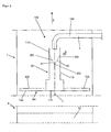
- FIG. 3 shows in distinction to FIG. 1 a liquid distributor 100 having a main channel 110 extending along a direction of extension E perpendicular to the longitudinal axis L and branching arms 120 departing therefrom, via their distribution holes 104, which are respectively provided in trays 122 of the distributing arms 120, the liquid phase F onto an underlying filling 10 of FIG Column 1 can be distributed.
- the main channel 110 and the distributing arms 120 each have outgoing walls 113 and 123, respectively, from the associated bottoms 112 and 122.
- the wall 113 of the main channel 110 is open at the top, so that the liquid phase F to be distributed can in turn be introduced into the main channel 110 via a line 150 whose outlet is placed above the main channel 150.
- a means 20 extending substantially over the entire cross section of the main channel 110 is now arranged in the main channel 110 in the form of a screen 20, which consists of two flat legs 201, 202 extending along the extension direction E. is to run toward each other in the direction of a bottom 112 of the main channel 110, so that the sieve 20 has an edge or free end region 203 extending along the extension direction E.
- the liquid F introduced onto the wire 20 via the line 150 is additionally calmed by the wire 20 (see above), which likewise improves the quality of the distribution, since the formation of as constant a level as possible in the closed distribution arms 120 is thus supported.
- FIG. 4 shows in a perspective view of a liquid distributor 100 with a distribution chamber 101, in turn from a along a direction of extension E main channel 110 extending with bottom 112 and 113 departing wall therefrom several Verteilarme 120 to both sides of the main channel 110 depart whose bottoms 122 in an extension plane with the bottom 112 of the main channel 110, wherein from the floors 122 of the Verteilarme 120 outgoing walls 123 of the Verteilarme 120 along the vertical Z in particular the same height as the wall 113 of the main channel 110th
- the main channel 110 and possibly the Verteilarme 120 are open at the top, so that according to FIG. 3 a liquid phase F to be distributed can also be introduced from above into the main channel 110.
- a sieve 20 in the manner of FIG. 3 arranged which serves to filter the liquid to be distributed F and thus prevents closing of the distribution holes 104 of the liquid distributor 100, which leads to an improvement in the distribution quality of the manifold 100.
- FIG. 5 shows a liquid distributor 100 in the manner of FIG. 4 , unlike the FIG. 4 no sieve 20 according to FIG. 4 is disposed in the main channel 110, but a plurality of side by side and one above the other positioned filling elements 20 which cover the bottom 112 of the main channel 110 and the floors 122 of the Verteilarme 120, thereby forming a three-dimensional pack having a plurality of narrow passages 21 for the distributed Liquid F provides (the individual filling elements 20 abut each other).
- This promotes the quality of distribution of the liquid distributor 100 since on the one hand the liquid phase F introduced into the distribution space 101 is braked and, in particular, calmed down with regard to lateral movements (waves).
- the high effective surface area of the filling elements 20 in their entirety supports the degassing of the liquid F within the distribution space 101.
- FIG. 6 shows finally a liquid distributor 100, which has a distribution space 101 formed as a collecting space or whose distribution space 101 comprises at least one such collecting space.
- the collecting space 101 in this case has a bottom 102, from which a circumferential wall 103 goes off.
- the bottom 102 has a plurality of rectangular through-openings, from the peripheral edges of each circumferential walls 131 along the vertical Z depart, so that distribution chimneys 130 are formed, through which a ascending in the column 1 gaseous phase up through the plenum 101 therethrough can be directed.
- the bottom 102 also has distribution holes 104, through which the liquid phase F can be applied to a cross section of a filling 10 of a column 1 arranged below the collecting space 101.
- the walls 131 of the distribution chimneys 130 each delimit chimney openings 132, which may possibly be roofed over, so that a liquid phase F flowing downwards in the column 1 can not penetrate into the distribution chimneys 130.
- the collecting space 101 may in particular be arranged below a filling 10 of a column 1 and receive the outflowing liquid phase F and further distribute it via the distribution holes 104 arranged in the bottom 102.
- the respective chimney openings 132 are to be roofed (see above). It is of course also possible that the liquid phase F to be distributed to the collecting space 101 via a line of the type FIGS. 1 or 3 is forwarded.
Landscapes
- Engineering & Computer Science (AREA)
- Chemical & Material Sciences (AREA)
- Mechanical Engineering (AREA)
- Chemical Kinetics & Catalysis (AREA)
- General Engineering & Computer Science (AREA)
- Thermal Sciences (AREA)
- Physics & Mathematics (AREA)
- Analytical Chemistry (AREA)
- General Chemical & Material Sciences (AREA)
- Oil, Petroleum & Natural Gas (AREA)
- Combustion & Propulsion (AREA)
- Physical Or Chemical Processes And Apparatus (AREA)
- Vaporization, Distillation, Condensation, Sublimation, And Cold Traps (AREA)
- Feeding, Discharge, Calcimining, Fusing, And Gas-Generation Devices (AREA)
- Filtration Of Liquid (AREA)
Applications Claiming Priority (1)
| Application Number | Priority Date | Filing Date | Title |
|---|---|---|---|
| DE102010056023A DE102010056023A1 (de) | 2010-12-23 | 2010-12-23 | Kolonne |
Publications (1)
| Publication Number | Publication Date |
|---|---|
| EP2468376A1 true EP2468376A1 (fr) | 2012-06-27 |
Family
ID=45318768
Family Applications (1)
| Application Number | Title | Priority Date | Filing Date |
|---|---|---|---|
| EP11009611A Withdrawn EP2468376A1 (fr) | 2010-12-23 | 2011-12-06 | Distributeur de liquide pour colonne avec garnissage |
Country Status (5)
| Country | Link |
|---|---|
| US (1) | US20120160453A1 (fr) |
| EP (1) | EP2468376A1 (fr) |
| JP (1) | JP2012130912A (fr) |
| KR (1) | KR20120072334A (fr) |
| DE (1) | DE102010056023A1 (fr) |
Families Citing this family (7)
| Publication number | Priority date | Publication date | Assignee | Title |
|---|---|---|---|---|
| JP5767609B2 (ja) * | 2012-06-25 | 2015-08-19 | 株式会社東芝 | 二酸化炭素回収装置及びその運転方法 |
| DE102015121037A1 (de) * | 2015-12-03 | 2017-06-08 | Thyssenkrupp Ag | Vorrichtung zur Sauerstoffverteilung in einem Oxidationsreaktor, Oxidationsreaktor und Anlage mit einer solchen Vorrichtung und Betriebsverfahren |
| CN106768126A (zh) * | 2016-12-29 | 2017-05-31 | 新疆熙泰石油装备有限公司 | 对冲式集液分布器 |
| FI128517B (en) * | 2018-12-28 | 2020-07-15 | Neste Oyj | Apparatus and method for heat treating input materials comprising lipid materials |
| FI129367B (en) | 2018-12-28 | 2021-12-31 | Neste Oyj | METHOD FOR HANDLING LIPID - CONTAINING MATERIALS |
| EP3719433A1 (fr) * | 2019-04-02 | 2020-10-07 | Linde GmbH | Distributeur de fluide réglable d'un échangeur de chaleur enroulé permettant de réaliser des différentes charges de fluide |
| FR3100320B1 (fr) * | 2019-09-02 | 2022-02-18 | Air Liquide | Dispositif de distribution destiné à une colonne de séparation gaz/liquide |
Citations (4)
| Publication number | Priority date | Publication date | Assignee | Title |
|---|---|---|---|---|
| DE973623C (de) * | 1952-09-26 | 1960-04-14 | Bayer Ag | Vorrichtung zur Fluessigkeitsverteilung in Kolonnen |
| EP1316345A1 (fr) * | 2001-11-21 | 2003-06-04 | Air Products And Chemicals, Inc. | Distributeur de liquide avec déflecteur interne |
| EP1386649A1 (fr) * | 2002-07-30 | 2004-02-04 | Air Products And Chemicals, Inc. | Distributeur de liquide |
| WO2008027718A2 (fr) * | 2006-08-30 | 2008-03-06 | Uop Llc | Dispositif et procédé permettant de diffuser un liquide |
Family Cites Families (11)
| Publication number | Priority date | Publication date | Assignee | Title |
|---|---|---|---|---|
| US2290162A (en) * | 1941-01-10 | 1942-07-21 | Foster Wheeler Corp | Vapor and liquid contact apparatus |
| DE2901935C2 (de) * | 1979-01-19 | 1986-01-09 | Linde Ag, 6200 Wiesbaden | Wärme- und Stoffaustauschkolonne |
| US4950430A (en) * | 1986-12-01 | 1990-08-21 | Glitsch, Inc. | Structured tower packing |
| US5237823A (en) * | 1992-03-31 | 1993-08-24 | Praxair Technology, Inc. | Cryogenic air separation using random packing |
| US5534233A (en) * | 1993-12-15 | 1996-07-09 | Chiyoda Corporation | Liquid flow control device, reactor using same and liquid flow control method |
| US5407605A (en) * | 1993-12-16 | 1995-04-18 | Uop | Fractionation tray with side discharging triangular downcomers |
| US6527258B2 (en) * | 1999-03-19 | 2003-03-04 | Sulzer Chemtech Ag | Apparatus for the collection and distribution of liquid in a column |
| DE10010810A1 (de) * | 2000-03-08 | 2001-09-13 | Montz Gmbh Julius | Flüssigkeitsverteiler und Verfahren zum Betreiben |
| DE10124386A1 (de) * | 2001-05-18 | 2002-11-28 | Basf Ag | Verfahren zur Destillation oder Reaktivdestillation eines Gemisches, das mindestens eine toxische Komponente enthält |
| DE10221761A1 (de) * | 2002-05-16 | 2003-11-27 | Montz Gmbh Julius | Packung für Wärme- und Stoffaustausch |
| US20110185902A1 (en) * | 2008-06-06 | 2011-08-04 | Rupert Wagner | Column for bringing two fluids into contact |
-
2010
- 2010-12-23 DE DE102010056023A patent/DE102010056023A1/de not_active Withdrawn
-
2011
- 2011-12-06 EP EP11009611A patent/EP2468376A1/fr not_active Withdrawn
- 2011-12-21 JP JP2011279273A patent/JP2012130912A/ja active Pending
- 2011-12-22 US US13/334,543 patent/US20120160453A1/en not_active Abandoned
- 2011-12-22 KR KR1020110140207A patent/KR20120072334A/ko not_active Withdrawn
Patent Citations (4)
| Publication number | Priority date | Publication date | Assignee | Title |
|---|---|---|---|---|
| DE973623C (de) * | 1952-09-26 | 1960-04-14 | Bayer Ag | Vorrichtung zur Fluessigkeitsverteilung in Kolonnen |
| EP1316345A1 (fr) * | 2001-11-21 | 2003-06-04 | Air Products And Chemicals, Inc. | Distributeur de liquide avec déflecteur interne |
| EP1386649A1 (fr) * | 2002-07-30 | 2004-02-04 | Air Products And Chemicals, Inc. | Distributeur de liquide |
| WO2008027718A2 (fr) * | 2006-08-30 | 2008-03-06 | Uop Llc | Dispositif et procédé permettant de diffuser un liquide |
Also Published As
| Publication number | Publication date |
|---|---|
| JP2012130912A (ja) | 2012-07-12 |
| KR20120072334A (ko) | 2012-07-03 |
| DE102010056023A1 (de) | 2012-06-28 |
| US20120160453A1 (en) | 2012-06-28 |
Similar Documents
| Publication | Publication Date | Title |
|---|---|---|
| DE69416846T2 (de) | Vorrichtung zum verteilen, mischen und entnehmen eines monophasischen fluidums für feststoffpartikelbetten | |
| EP0112978B1 (fr) | Distributeur de liquide pour une colonne d'échange de masse et ou de chaleur | |
| DE60116269T2 (de) | Austauschbare stützstruktur mit mehreren leitungen für radiales strömungssystem | |
| EP0282753B2 (fr) | Dispositif pour la distribution uniforme d'un liquide sur des parties d'échanges d'une colonne d'échange de matière et de chaleur | |
| DE1238447B (de) | Vorrichtung zur Verteilung einer Fluessigkeit | |
| CH642566A5 (de) | Trogartige vorrichtung zum sammeln und verteilen der fluessigkeit in einer gegenstromkolonne. | |
| DE102010056023A1 (de) | Kolonne | |
| EP0456750B1 (fr) | Conteneur avec tremie de decharge pour materiau en vrac | |
| DE1519711B2 (de) | Zuführen eines Dampf-Flüssigkeits-Gemisches in Stoffaustauschkolonnen | |
| DE1961783C3 (de) | Vorrichtung zum Inberührungbringen von gasförmigen und/oder flüssigen Medien mit einem Festbett aus körnigem Feststoff | |
| DE2336971C3 (de) | Vorrichtung für das Verteilen der Strömung eines fließfähigen Stoffes | |
| EP0231841B1 (fr) | Dispositif pour la distribution uniforme d'un liquide contenant des matières solides sur une section transversale | |
| EP0552457A1 (fr) | Plaque distributrice destinée à un réacteur à lit mobile | |
| EP0553180B1 (fr) | Reacteur a milieu d'adsorption, notamment a lit fluidise | |
| WO2017194203A1 (fr) | Dispositif de collecte de liquide, colonne de transfert de matière et procédé de fabrication d'un tel dispositif de collecte de liquide | |
| DE69027693T2 (de) | Doppelstöckiger Verteiler | |
| DE102007007582A1 (de) | Gas-Flüssigkeits-Verteiler zur Einspeisung eines zweiphasigen Feeds in eine Kolonne | |
| DE102011103634A1 (de) | Flüssigkeitsverteiler | |
| WO2007045666A1 (fr) | Dispositif repartiteur de melange de phases gazeuse et liquide pour des appareils | |
| DE102008007099B4 (de) | Tropfenabscheidereinheit | |
| EP0089486A2 (fr) | Colonne à plusieurs enceintes fluidisées | |
| DE2953476A1 (de) | Destillationsplatte | |
| DE3240987A1 (de) | Verteil- und sammelvorrichtung | |
| EP1928567A1 (fr) | Dispositif et procede de repartition de deux liquides non miscibles | |
| DE102010009292A1 (de) | Gas-Flüssigkeits-Verteiler für ein zweiphasiges Feed mit einer Materialschicht im Flüssigkeitsablauf |
Legal Events
| Date | Code | Title | Description |
|---|---|---|---|
| AK | Designated contracting states |
Kind code of ref document: A1 Designated state(s): AL AT BE BG CH CY CZ DE DK EE ES FI FR GB GR HR HU IE IS IT LI LT LU LV MC MK MT NL NO PL PT RO RS SE SI SK SM TR |
|
| AX | Request for extension of the european patent |
Extension state: BA ME |
|
| PUAI | Public reference made under article 153(3) epc to a published international application that has entered the european phase |
Free format text: ORIGINAL CODE: 0009012 |
|
| 17P | Request for examination filed |
Effective date: 20130410 |
|
| 17Q | First examination report despatched |
Effective date: 20130917 |
|
| STAA | Information on the status of an ep patent application or granted ep patent |
Free format text: STATUS: THE APPLICATION IS DEEMED TO BE WITHDRAWN |
|
| 18D | Application deemed to be withdrawn |
Effective date: 20140128 |