EP2468463A2 - Procédé et dispositif de génération de trajectoire de revêtement - Google Patents
Procédé et dispositif de génération de trajectoire de revêtement Download PDFInfo
- Publication number
- EP2468463A2 EP2468463A2 EP11189566A EP11189566A EP2468463A2 EP 2468463 A2 EP2468463 A2 EP 2468463A2 EP 11189566 A EP11189566 A EP 11189566A EP 11189566 A EP11189566 A EP 11189566A EP 2468463 A2 EP2468463 A2 EP 2468463A2
- Authority
- EP
- European Patent Office
- Prior art keywords
- path
- spray
- component
- motion path
- simulated
- Prior art date
- Legal status (The legal status is an assumption and is not a legal conclusion. Google has not performed a legal analysis and makes no representation as to the accuracy of the status listed.)
- Granted
Links
Images


Classifications
-
- B—PERFORMING OPERATIONS; TRANSPORTING
- B25—HAND TOOLS; PORTABLE POWER-DRIVEN TOOLS; MANIPULATORS
- B25J—MANIPULATORS; CHAMBERS PROVIDED WITH MANIPULATION DEVICES
- B25J9/00—Program-controlled manipulators
- B25J9/16—Program controls
- B25J9/1656—Program controls characterised by programming, planning systems for manipulators
- B25J9/1671—Program controls characterised by programming, planning systems for manipulators characterised by simulation, either to verify existing program or to create and verify new program, CAD/CAM oriented, graphic oriented programming systems
-
- B—PERFORMING OPERATIONS; TRANSPORTING
- B05—SPRAYING OR ATOMISING IN GENERAL; APPLYING FLUENT MATERIALS TO SURFACES, IN GENERAL
- B05B—SPRAYING APPARATUS; ATOMISING APPARATUS; NOZZLES
- B05B12/00—Arrangements for controlling delivery; Arrangements for controlling the spray area
- B05B12/08—Arrangements for controlling delivery; Arrangements for controlling the spray area responsive to condition of liquid or other fluent material to be discharged, of ambient medium or of target ; responsive to condition of spray devices or of supply means, e.g. pipes, pumps or their drive means
- B05B12/084—Arrangements for controlling delivery; Arrangements for controlling the spray area responsive to condition of liquid or other fluent material to be discharged, of ambient medium or of target ; responsive to condition of spray devices or of supply means, e.g. pipes, pumps or their drive means responsive to condition of liquid or other fluent material already sprayed on the target, e.g. coating thickness, weight or pattern
-
- F—MECHANICAL ENGINEERING; LIGHTING; HEATING; WEAPONS; BLASTING
- F01—MACHINES OR ENGINES IN GENERAL; ENGINE PLANTS IN GENERAL; STEAM ENGINES
- F01D—NON-POSITIVE DISPLACEMENT MACHINES OR ENGINES, e.g. STEAM TURBINES
- F01D5/00—Blades; Blade-carrying members; Heating, heat-insulating, cooling or antivibration means on the blades or the members
- F01D5/12—Blades
- F01D5/28—Selecting particular materials; Particular measures relating thereto; Measures against erosion or corrosion
- F01D5/288—Protective coatings for blades
-
- B—PERFORMING OPERATIONS; TRANSPORTING
- B05—SPRAYING OR ATOMISING IN GENERAL; APPLYING FLUENT MATERIALS TO SURFACES, IN GENERAL
- B05B—SPRAYING APPARATUS; ATOMISING APPARATUS; NOZZLES
- B05B13/00—Machines or plants for applying liquids or other fluent materials to surfaces of objects or other work by spraying, not covered by groups B05B1/00 - B05B11/00
- B05B13/02—Means for supporting work; Arrangement or mounting of spray heads; Adaptation or arrangement of means for feeding work
- B05B13/04—Means for supporting work; Arrangement or mounting of spray heads; Adaptation or arrangement of means for feeding work the spray heads being moved during spraying operation
- B05B13/0431—Means for supporting work; Arrangement or mounting of spray heads; Adaptation or arrangement of means for feeding work the spray heads being moved during spraying operation with spray heads moved by robots or articulated arms, e.g. for applying liquid or other fluent material to three-dimensional [3D] surfaces
-
- B—PERFORMING OPERATIONS; TRANSPORTING
- B05—SPRAYING OR ATOMISING IN GENERAL; APPLYING FLUENT MATERIALS TO SURFACES, IN GENERAL
- B05B—SPRAYING APPARATUS; ATOMISING APPARATUS; NOZZLES
- B05B7/00—Spraying apparatus for discharge of liquids or other fluent materials from two or more sources, e.g. of liquid and air, of powder and gas
- B05B7/16—Spraying apparatus for discharge of liquids or other fluent materials from two or more sources, e.g. of liquid and air, of powder and gas incorporating means for heating or cooling the material to be sprayed
- B05B7/20—Spraying apparatus for discharge of liquids or other fluent materials from two or more sources, e.g. of liquid and air, of powder and gas incorporating means for heating or cooling the material to be sprayed by flame or combustion
-
- F—MECHANICAL ENGINEERING; LIGHTING; HEATING; WEAPONS; BLASTING
- F05—INDEXING SCHEMES RELATING TO ENGINES OR PUMPS IN VARIOUS SUBCLASSES OF CLASSES F01-F04
- F05D—INDEXING SCHEME FOR ASPECTS RELATING TO NON-POSITIVE-DISPLACEMENT MACHINES OR ENGINES, GAS-TURBINES OR JET-PROPULSION PLANTS
- F05D2230/00—Manufacture
- F05D2230/90—Coating; Surface treatment
-
- F—MECHANICAL ENGINEERING; LIGHTING; HEATING; WEAPONS; BLASTING
- F05—INDEXING SCHEMES RELATING TO ENGINES OR PUMPS IN VARIOUS SUBCLASSES OF CLASSES F01-F04
- F05D—INDEXING SCHEME FOR ASPECTS RELATING TO NON-POSITIVE-DISPLACEMENT MACHINES OR ENGINES, GAS-TURBINES OR JET-PROPULSION PLANTS
- F05D2300/00—Materials; Properties thereof
- F05D2300/60—Properties or characteristics given to material by treatment or manufacturing
- F05D2300/611—Coating
-
- G—PHYSICS
- G05—CONTROLLING; REGULATING
- G05B—CONTROL OR REGULATING SYSTEMS IN GENERAL; FUNCTIONAL ELEMENTS OF SUCH SYSTEMS; MONITORING OR TESTING ARRANGEMENTS FOR SUCH SYSTEMS OR ELEMENTS
- G05B2219/00—Program-control systems
- G05B2219/30—Nc systems
- G05B2219/35—Nc in input of data, input till input file format
- G05B2219/35343—Display path and coating thickness and painting time
-
- G—PHYSICS
- G05—CONTROLLING; REGULATING
- G05B—CONTROL OR REGULATING SYSTEMS IN GENERAL; FUNCTIONAL ELEMENTS OF SUCH SYSTEMS; MONITORING OR TESTING ARRANGEMENTS FOR SUCH SYSTEMS OR ELEMENTS
- G05B2219/00—Program-control systems
- G05B2219/30—Nc systems
- G05B2219/40—Robotics, robotics mapping to robotics vision
- G05B2219/40518—Motion and task planning
-
- G—PHYSICS
- G05—CONTROLLING; REGULATING
- G05B—CONTROL OR REGULATING SYSTEMS IN GENERAL; FUNCTIONAL ELEMENTS OF SUCH SYSTEMS; MONITORING OR TESTING ARRANGEMENTS FOR SUCH SYSTEMS OR ELEMENTS
- G05B2219/00—Program-control systems
- G05B2219/30—Nc systems
- G05B2219/45—Nc applications
- G05B2219/45013—Spraying, coating, painting
Definitions
- the present invention relates to a method and a device for generating a motion path for a spray gun for coating a component.
- the present invention especially relates to a method of an automatic coating path generation for a component with a complicated geometry such as turbine blades and vanes, especially gas turbine blades and vanes.
- the thickness distribution is one of the most important parameter of the coatings.
- the coating thickness defines not only the amount of the sprayed powder, but the functional properties of the coating and as a consequence the properties of the coated component in the production environment.
- the thickness distribution of the protective coatings applied to the turbine components define the life time of the whole component in the turbine.
- the offline robot programming methods use various software tools for the realistic simulation of the robot motion.
- the planning of the robot path is based on the CAD data of the component surface geometry and executed by a software operator in the interactive mode.
- the final verification and development of the resulting coating needs an iterative process of the subsequent coating booth trials, coating thickness analysis and adjustment of the spray path to reach the desired coating distribution on the whole component.
- the next step of the simulation tools development is an offline coating thickness simulation.
- An offline thickness simulation requires a modelling of the primitive spray pattern in form of the spray spot or spray profile. For this reason the physical modelling or pattern database concepts could be used.
- the realistic modelling of the coating thickness needs to reflect the changes of the pattern in dependence on the variation of the relevant process parameters during the coating process.
- the thickness simulation could be implemented into the robotic simulation software
- the document US 6,256,597 relates to a spray coating simulation for a robotic spray gun assembly which imports a discretized model of an object geometry.
- the simulator imports a numerically characterized spray pattern file and a robot motion file having a plurality of motion positions, dwell times and orientations defining a motion path of the spray gun.
- the individual motion positions within the motion file are read and a determination is made as to which portions of the object geometry are visible at each motion position.
- a coating thickness at each visible portion of the object geometry is computed, based on the specified spray pattern data, the dwell time and the orientation of the robot motion path, for each motion position.
- the total coating thickness over the object geometry is calculated.
- the first objective is solved by a method as claimed in claim 1.
- the second objective is solved by a device as claimed in claim 15.
- the depending claims define further developments of the invention.
- the motion path can be a robot motion path.
- the spray gun can be a robot spray gun.
- the simulation and the generation of the motion path can be performed offline.
- the first motion path can be generated offline and/or the coating thickness of the motion path can be simulated offline.
- the path templates for the surface segments of the component can be defined based on a database of the component.
- the surface of the surface segments can be analysed based on a database of the components.
- the first motion path can be generated based on a database of the component.
- the database of the component comprises CAD (Computer Aided Design) data, preferably in a standardized format.
- Generic components can be defined according to characteristic features and/or attributes to simplify the generation of the first motion path for the particular component.
- the components can be divided into groups according to characteristic features or attributes to simplify the generation of the first robotic path for the particular component.
- a standard gas turbine blade and/or a standard gas turbine vane can be defined as generic component, for instance.
- a standard path template can be defined which represents a set of standard spray path segments corresponding to the characteristic surface areas to be coated, for example with separate spray path blocks.
- the standard path segments may be the pressure side and/or the suction side and/or the leading edge and/or the root platform.
- the path template can be adjusted to the dimensions of the particular component based on the database of the component.
- the motion path can be automatically generated in the same virtual spray booth for similar components with a scaling algorithm.
- the position and/or the orientation of a spray gun at a location corresponding to the path template can be correlated to the position and/or the orientation of the component surface, for example based on the particular geometric and/or kinematical spray parameters.
- the position and/or the orientation of a spray gun at a location corresponding to the path template can be correlated to the position and/or the orientation of the component surface based on a particular path offset and/or a particular spray distance and/or a particular spray angle range and/or a particular overspray distance and/or a particular spray gun speed and/or a particular gun positioning accuracy.
- the geometric spray parameters such as the spray angle or a spray distance can be change to improve the spray path.
- the first motion path especially the first robotic motion path, can be ready for a dry simulation run.
- the functionality for a realistic robot motion simulation can be checked based on joint limits for a robot to reach the locations of the path template, for example by using appropriate software.
- Geometric spray parameters like the spray angle or the spray distance, for example, may be adapted depending on the results of the functionality check and/or the collision check.
- this adaptive algorithm will allow to set a complete designed robotic path for a definite component as a template.
- the generation of the path for the components with a similar geometry but with different dimensions can be done by scaling of the relevant path parameters from one component to another taking into account a spatial distortion of the component dimensions.
- the thickness distribution on the spray profile can be simulated as a Gaussian distribution.
- the simulated model of the spray profile may represent a thickness equation describing the thickness distribution in a primitive pattern, for example in dependence on the distance from the pattern centre and/or the process parameters and/or a library of spray patters corresponding to different sets of process parameters.
- the thickness on the whole effected surface can be simulated based on an accumulative value of the thicknesses applied by a number of spray profiles according to the motion of the spray gun.
- Motion path segments effecting the thickness distribution at the area were the simulated coating thickness not achieves the predetermined tolerances can be identified, analysed and automatically adjusted. This can, for example, be achieved by changing the gun speed and/or the path offset and/or the spay angle.
- the iterative process of the robotic path adjustment can be performed until the desired coating thickness is achieved on the whole component.
- the inventive method provides an automatic coating path generation for the components with complicated geometry such as turbine blades and vanes.
- the method uses an advanced approach for the robotic path creation based on the simultaneous analysis of the, for example, CAD data of the surface geometry with application of the offline coating thickness simulation for an iterative adjustment of the path to reach the desired coating distribution.
- the component surface may be coated by atmospheric plasma spraying (APF), high velocity oxygen fuel spraying (HVOF), low pressure plasma spraying (LPPS), thermal spray coating deposition, laser cladding, wire arc spraying, cold spraying, sensor deposition or generic painting.
- API atmospheric plasma spraying
- HVOF high velocity oxygen fuel spraying
- LPPS low pressure plasma spraying
- thermal spray coating deposition laser cladding
- wire arc spraying cold spraying
- sensor deposition sensor deposition or generic painting.
- the implementation of the offline coating thickness simulation in combination with the offline robotic simulation enables to predict and analyze the thickness distribution mapped on the CAD component surface.
- the initial robotic path after the analysis of the simulated thickness distribution can be adjusted by the operator without a subsequent booth trial to verify the coating thickness at the intermediate path development steps.
- the combination of the offline robotic simulation with the offline coating thickness simulation enables a semi-virtual process of the spray path development.
- the present invention provides an automatic spray path generation based on the component surface geometry from the CAD data and an iterative adjustment of the spray path using the thickness data resulting from the offline coating thickness simulation.
- the inventive device for generating a motion path for a spray gun for coating a component comprises:
- Figure 1 schematically shows a process diagram of an automatic motion path, especially an automatic spray path, generation.
- components data base for example CAD design data
- path templates for surface segments of the components.
- reference numerals 1 and 2 are used to define path templates for surface segments of the components.
- reference numeral 3 the surface of the surface segments is analysed based on the CAD model.
- a first motion path for example a first robotic path, is offline generated based on the CAD data. This is represented by reference numeral 4.
- a model of a spray profile is simulated and the coating thickness for the motion path, for example for the robotic path, is offline simulated based on the simulated model of the spray profile and the generated first motion path.
- This is represented in Figure 1 by reference numerals 4, 5 and 6.
- the simulated coating thickness is compared with predetermined tolerances, which means that it is checked, if the simulated thickness is within the predetermined tolerances. This is represented by reference numeral 7.
- the simulation is finished.
- the end of the process is designated by reference numeral 9.
- an adaptive motion path is generated or adjusted based on the simulated thickness and the components data, for example the CAD data.
- the generation or adjustment of the adapted motion path is indicated by reference numeral 8.
- the coating thickness for the adapted motion path is simulated again, which means the process runs again through the steps 6 and 7.
- step 9 is achieved, which means that the thickness is within the predetermined tolerances.
- FIG. 2 schematically shows a model of a gas turbine blade, for example a CAD model, loaded into a virtual simulation environment.
- the blade 10 comprises a root portion 14, a platform 15 and an airfoil portion 27.
- the airfoil portion 27 is connected to the platform 15.
- the root portion 14 is also connected to the platform 15.
- the airfoil portion comprises a pressure side 18 and a suction side 19. It further comprises a leading edge 16 and a trailing edge 17.
- the airfoil portion 27 is coated with a coating material 25 by means of a spray gun 24.
- the spray gun 24 is connected to a robot tool.
- the robot tool comprises a fixation means 26 for connecting the spray gun 24 to the robot.
- the robot further comprises at least one robot boom 23 to move the spray gun 24 along a motion path.
- the components data base 1 can contain available CAD models of the components in a standardized format.
- the components are divided into groups according to the characteristic features and attributes to simplify the creation of the first robotic path for the particular component.
- it can be definite as generic components a standard gas turbine blade and a standard gas turbine vane with all relevant characteristic features of the outer component surface.
- a standard path template which represents a standard set of the spray path segments 2 corresponding to the characteristic surface areas to be coated with the separate spray path blocks.
- the pressure and suction sides of the airfoil the leading edge and separated areas of the root platform could be chosen as the standard path segments.
- the CAD model of the component from the data base 1 can be downloaded into a virtual environment of simulation software with the necessary input of the generic type of the component to choose the corresponding path template.
- the virtual software environment (for example see Figure 2 ) represents an exact geometrical model of the coating boot including a robot, component fixture and relevant auxiliary tools.
- the path template is adjusted to the dimensions of the particular component.
- the positions and orientation of the robotic locations corresponding to the spray path template can be put corresponding to the position and orientation of the component surface.
- an input of the particular geometric and kinematical spray parameters such as path offset, spray distance, spray angles range, overspray distance, spray gun speed. gun positioning accuracy, etc. is needed.
- the first robotic path 4 can be created and adjusted with respect to the reachability of the robotic locations.
- the joint limits for the robot to reach the locations of the template spray path are checked.
- a collision check is carried out in order to prevent collisions between the spray tools such as the spray gun 24 attached to the robot and the component 10 to be sprayed or with other auxiliary tools in the spraying cell.
- the geometric spray parameters such as a spray angle or a spray distance can be changed to improve the spray path.
- this adaptive algorithm allows to set a complete designed robotic path for a definite component as a template.
- the generation of the path for the components with a similar geometry but with different dimensions can be done by scaling of the relevant path parameters from one component to another taking into account a spatial distortion of the component dimensions.
- the spray path 4 created by the template 3 represents a draft path not ensuring the resulting coating thickness distribution to stay in the desired tolerances for the whole component.
- an offline coating simulation 6 for a draft robotic path is carried out.
- a necessary condition for a coating simulation is an existence of the simulation model 5 for the primitive spray pattern such as a spray spot or a spray profile.
- the spray spot represents a coating pattern on a flat surface resulting from the spraying from the fixed position of the spray gun at some period of time.
- the spray profile is a result of the linear motion of the spray gun with constant surface speed.
- the simulation model can represent a thickness equation describing the thickness distribution in the primitive pattern in dependence on the distance from the pattern centre and the process parameters or the library of the spray patterns corresponding to the different sets of the process parameters or a combination of both. For example a single profile of the thermal spray coatings can with a high accuracy be modelled as a Gaussian distribution.
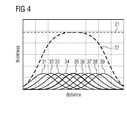
- Figure 4 schematically shows the accumulation of the total layer thickness 22 of the coating by the application of single spray profiles.
- the different spray paths are designated by reference numerals 31 to 39.
- the single Gaussian profiles result in a total coating thickness 22.
- the predetermined tolerance or desired thickness is designated by reference numeral 21.
- the thickness distribution resulting from the draft spray path is automatically analyzed 7. If the thickness values stay in the tolerance range no additional development of the robotic path is needed and the process is completed.
- the resulting thickness distribution changes not only at the desired areas but possibly at the other areas affected by the changed path segments.
- a subsequent coating simulation is needed to prove the coating distribution on the whole component or in some cases only at the affected areas.
- the described iterative process of the robotic path adjustment is performed until the desired coating thickness is achieved on the whole component.
Landscapes
- Engineering & Computer Science (AREA)
- Mechanical Engineering (AREA)
- Chemical & Material Sciences (AREA)
- Materials Engineering (AREA)
- General Engineering & Computer Science (AREA)
- Robotics (AREA)
- Application Of Or Painting With Fluid Materials (AREA)
- Spray Control Apparatus (AREA)
- Details Or Accessories Of Spraying Plant Or Apparatus (AREA)
- Coating By Spraying Or Casting (AREA)
Applications Claiming Priority (1)
| Application Number | Priority Date | Filing Date | Title |
|---|---|---|---|
| US12/974,233 US20120156362A1 (en) | 2010-12-21 | 2010-12-21 | Method and device for coating path generation |
Publications (3)
| Publication Number | Publication Date |
|---|---|
| EP2468463A2 true EP2468463A2 (fr) | 2012-06-27 |
| EP2468463A3 EP2468463A3 (fr) | 2013-01-02 |
| EP2468463B1 EP2468463B1 (fr) | 2014-06-18 |
Family
ID=45094466
Family Applications (1)
| Application Number | Title | Priority Date | Filing Date |
|---|---|---|---|
| EP11189566.0A Not-in-force EP2468463B1 (fr) | 2010-12-21 | 2011-11-17 | Procédé et dispositif de génération de trajectoire de revêtement |
Country Status (5)
| Country | Link |
|---|---|
| US (1) | US20120156362A1 (fr) |
| EP (1) | EP2468463B1 (fr) |
| JP (1) | JP2012149342A (fr) |
| CN (1) | CN102567579A (fr) |
| RU (1) | RU2011152103A (fr) |
Cited By (10)
| Publication number | Priority date | Publication date | Assignee | Title |
|---|---|---|---|---|
| WO2013041184A1 (fr) * | 2011-09-23 | 2013-03-28 | Dürr Systems GmbH | Procédé de revêtement et dispositif de revêtement ayant une compensation des asymétries du jet de pulvérisation |
| WO2013037693A3 (fr) * | 2011-09-15 | 2013-06-06 | Convergent Information Technologies Gmbh | Système et procédé de développement automatisé de programmes de robots |
| WO2014025518A1 (fr) * | 2012-08-08 | 2014-02-13 | Abb Technology Ag | Système et procédé de détermination d'une trajectoire optimale pour des robots de distribution de matière |
| WO2014093144A1 (fr) * | 2012-12-10 | 2014-06-19 | Abb Technology Ag | Génération de programme de robot pour processus robotiques |
| EP2876183A3 (fr) * | 2013-11-20 | 2015-06-03 | Siemens Aktiengesellschaft | Procédé et dispositif d'application automatique d'un revêtement par pulvérisation |
| WO2016009120A1 (fr) * | 2014-07-18 | 2016-01-21 | Peugeot Citroen Automobiles Sa | Procede d'enduction avec projection d'image sur carrosserie |
| CN109317383A (zh) * | 2018-10-25 | 2019-02-12 | 佛山市顺德区东亚汽车部件有限公司 | 一种用于注塑件表面加工的高效能喷涂生产工艺及其系统 |
| US10296675B2 (en) | 2015-12-30 | 2019-05-21 | Abb Schweiz Ag | System and method for determining dynamic motion data in robot trajectory |
| WO2021239447A1 (fr) * | 2020-05-27 | 2021-12-02 | Dürr Systems Ag | Procédé de programmation d'une installation de revêtement et installation de revêtement correspondante |
| WO2023194301A1 (fr) * | 2022-04-04 | 2023-10-12 | Dürr Systems Ag | Procédé de simulation d'une installation de revêtement et installation de revêtement correspondante |
Families Citing this family (44)
| Publication number | Priority date | Publication date | Assignee | Title |
|---|---|---|---|---|
| JP5340455B1 (ja) * | 2012-05-30 | 2013-11-13 | ファナック株式会社 | オフラインプログラミング装置 |
| CN102909148B (zh) * | 2012-08-13 | 2014-10-29 | 东南大学 | 一种多喷枪自适应建模的喷涂路径自动生成方法 |
| US9144841B1 (en) * | 2012-11-15 | 2015-09-29 | The Boeing Company | In-mold metallization of composite structures |
| CN103838172B (zh) * | 2012-11-21 | 2018-02-16 | 上海宝钢工业技术服务有限公司 | 铜板喷涂作业中机器人喷枪轨迹的设置方法 |
| US9555441B2 (en) * | 2013-05-03 | 2017-01-31 | Abb Schweiz Ag | Dynamic synchronized masking and coating |
| KR101626306B1 (ko) * | 2013-09-06 | 2016-06-01 | 삼성중공업 주식회사 | 풍력발전기용 타워의 도장방법 |
| CN103480534B (zh) * | 2013-09-12 | 2016-01-20 | 江苏科技大学 | 机器人喷涂工件曲面造型方法 |
| CN103611646B (zh) * | 2013-12-09 | 2016-05-25 | 江苏科技大学 | 喷涂机器人空间路径规划方法 |
| US10127332B2 (en) * | 2013-12-23 | 2018-11-13 | Dassault Systemes Solidworks Corporation | Automatic motion of a computer-aided design model |
| WO2015138529A1 (fr) * | 2014-03-11 | 2015-09-17 | Ametek Precitech, Inc. | Processus de traitement de bord |
| CN104874536B (zh) * | 2015-05-21 | 2018-01-16 | 西安航空动力股份有限公司 | 一种双机器人对导向叶片组件进行自动喷涂的方法 |
| CN105045098B (zh) * | 2015-05-29 | 2017-11-21 | 希美埃(芜湖)机器人技术有限公司 | 一种机器人喷涂轨迹自动生成系统的控制方法 |
| CN104841593B (zh) * | 2015-05-29 | 2017-04-19 | 希美埃(芜湖)机器人技术有限公司 | 一种机器人自动喷涂系统的控制方法 |
| US10339233B2 (en) * | 2015-07-27 | 2019-07-02 | Siemens Industry Software Ltd. | Calculating thicknesses of applied coating material |
| US10401804B1 (en) * | 2015-12-29 | 2019-09-03 | Dassault Systemes Solidworks Corporation | Mate controller |
| JP6370821B2 (ja) | 2016-02-12 | 2018-08-08 | ファナック株式会社 | ロボットプログラムの教示を行うロボットプログラミング装置 |
| US10478846B2 (en) | 2016-05-02 | 2019-11-19 | Lockheed Martin Corporation | Dynamic coating thickness measurement and control |
| US10537910B2 (en) * | 2016-09-08 | 2020-01-21 | The Boeing Company | Master application paths for coatings |
| CN106507574B (zh) * | 2016-09-29 | 2019-01-25 | 成都真火科技有限公司 | 一种用于航空材料的喷涂方法 |
| CN106853433B (zh) * | 2016-12-30 | 2020-03-20 | 吉林省天大精益智能制造技术有限公司 | 基于云计算的汽车智能喷漆方法 |
| CN106995909B (zh) * | 2017-05-25 | 2019-02-15 | 扬州大学 | 一种柱形表面的均匀热喷涂方法 |
| KR101991053B1 (ko) * | 2017-07-27 | 2019-10-01 | 두림야스카와(주) | 차량 도장 로봇 시뮬레이션 방법 |
| US10969217B2 (en) * | 2017-08-04 | 2021-04-06 | Rolls-Royce North American Technologies, Inc. | Adaptive control of coating thickness |
| DE102017215725A1 (de) | 2017-09-07 | 2019-03-07 | Bayerische Motoren Werke Aktiengesellschaft | Vorrichtung und Verfahren zur Applikation eines Dicht- und/oder Beschichtungsstoffes |
| CN108636671B (zh) * | 2018-05-24 | 2020-08-04 | 盐城工学院 | 一种不规则面片偏置喷涂路径规划方法 |
| CN109093619B (zh) * | 2018-07-18 | 2021-06-25 | 扬州大学 | 一种曲面均匀热喷涂的机器人轨迹规划方法 |
| CA3120618A1 (fr) * | 2018-11-21 | 2020-05-28 | Basf Se | Procede et systeme de fabrication d'un element isole |
| CN109499796B (zh) * | 2018-12-20 | 2024-10-18 | 广东泽亨智能科技有限公司 | 一种涂层厚度检测装置及其喷涂系统和喷涂控制方法 |
| CN109865621B (zh) * | 2019-03-20 | 2021-03-19 | 青岛金光鸿智能机械电子有限公司 | 一种喷涂位姿拆分方法及应用 |
| EP3753683B1 (fr) * | 2019-06-17 | 2025-01-01 | Siemens Industry Software Ltd. | Procédé et système de génération d'un programme robotique pour un revêtement industriel |
| CN110640754B (zh) * | 2019-09-17 | 2021-01-22 | 爱仕达股份有限公司 | 一种炊具喷涂方法 |
| CN112241584B (zh) * | 2020-08-29 | 2024-05-07 | 盐城工学院 | 一种边界约束喷涂轨迹规划边界约束距离值的设定方法 |
| US11945117B2 (en) | 2021-03-10 | 2024-04-02 | Samsung Electronics Co., Ltd. | Anticipating user and object poses through task-based extrapolation for robot-human collision avoidance |
| US12103185B2 (en) * | 2021-03-10 | 2024-10-01 | Samsung Electronics Co., Ltd. | Parameterized waypoint generation on dynamically parented non-static objects for robotic autonomous tasks |
| US11833691B2 (en) | 2021-03-30 | 2023-12-05 | Samsung Electronics Co., Ltd. | Hybrid robotic motion planning system using machine learning and parametric trajectories |
| CN113106440A (zh) * | 2021-04-21 | 2021-07-13 | 西安交通大学 | 一种冷喷涂增材制造构件的外形控制方法 |
| CN113522664B (zh) * | 2021-07-12 | 2022-11-25 | 哈尔滨汽轮机厂有限责任公司 | 一种汽轮机热喷涂路径规划方法 |
| CN114474043B (zh) * | 2021-12-20 | 2024-05-31 | 埃夫特智能装备股份有限公司 | 一种床头视觉智能喷涂的实现方法 |
| CN114260156B (zh) * | 2021-12-27 | 2023-09-22 | 江苏源清动力技术有限公司 | 一种燃气轮机叶片曲面喷涂方法 |
| JP2024000746A (ja) * | 2022-06-21 | 2024-01-09 | 三菱重工業株式会社 | 成膜条件生成装置、成膜装置、成膜条件生成方法、成膜方法及び成膜条件生成プログラム |
| CN117987762B (zh) * | 2022-11-07 | 2024-07-16 | 苏州众芯联电子材料有限公司 | 一种减少下部电极表面熔射纹路工艺 |
| CN115846131B (zh) * | 2022-11-16 | 2025-10-28 | 杭州长川科技股份有限公司 | 多工位点胶机构位移转化方法及多工位点胶装置 |
| JP2024170936A (ja) * | 2023-05-29 | 2024-12-11 | 株式会社日立製作所 | 塗装作業管理装置、塗装作業管理プログラム、並びに塗装作業管理装置を用いて塗装された鉄道車両 |
| CN119871468A (zh) * | 2025-03-31 | 2025-04-25 | 广东省科学院新材料研究所 | 一种针对曲面叶片的喷涂路径生成方法、装置、设备及存储介质 |
Citations (1)
| Publication number | Priority date | Publication date | Assignee | Title |
|---|---|---|---|---|
| US6256597B1 (en) | 1998-07-10 | 2001-07-03 | General Electric Company | Three dimensional spray coating method and simulation |
Family Cites Families (6)
| Publication number | Priority date | Publication date | Assignee | Title |
|---|---|---|---|---|
| JP2779741B2 (ja) * | 1992-09-11 | 1998-07-23 | 新日本製鐵株式会社 | 被膜形成のための条件決定方法 |
| JP3448951B2 (ja) * | 1993-08-25 | 2003-09-22 | マツダ株式会社 | 塗装における塗装タレの評価方法及び塗装制御装置 |
| WO1998017837A1 (fr) * | 1996-10-21 | 1998-04-30 | Kabushiki Kaisha Toshiba | Systeme de pulverisation automatique et procede de pulverisation dans lequel les conditions de pulverisation sont determinees par ordinateur |
| JP4480148B2 (ja) * | 2004-09-24 | 2010-06-16 | 大日本印刷株式会社 | 転写用マスクのip測定装置および静電吸着方式のチャックへの静電吸着用電圧の供給方法 |
| EP1842631B1 (fr) * | 2006-04-03 | 2008-11-19 | ABB Research Ltd | Dispositif et méthode de génération de trajectoire pour un robot industriel |
| US7722916B2 (en) * | 2006-05-30 | 2010-05-25 | General Electric Company | Methods for controlling plasma spray coating porosity on an article and articles manufactured therefrom |
-
2010
- 2010-12-21 US US12/974,233 patent/US20120156362A1/en not_active Abandoned
-
2011
- 2011-11-17 EP EP11189566.0A patent/EP2468463B1/fr not_active Not-in-force
- 2011-12-20 CN CN2011104295094A patent/CN102567579A/zh active Pending
- 2011-12-20 JP JP2011278002A patent/JP2012149342A/ja active Pending
- 2011-12-20 RU RU2011152103/02A patent/RU2011152103A/ru not_active Application Discontinuation
Patent Citations (1)
| Publication number | Priority date | Publication date | Assignee | Title |
|---|---|---|---|---|
| US6256597B1 (en) | 1998-07-10 | 2001-07-03 | General Electric Company | Three dimensional spray coating method and simulation |
Non-Patent Citations (2)
| Title |
|---|
| FLORIN ILULLU TIFA ET AL.: "Model-based expert system for design and simulation of APS coatings", JOURNAL OF THERMAL SPRAY TECHNOLOGY, vol. 16, no. 1, 2007, pages 128 - 139, XP007920949, DOI: doi:10.1007/s11666-006-9000-9 |
| H-P. WANG: "Parameter optimization for spray coating method and simulation", GE. 1998, ENGINEERING SOFTWARE, vol. 40, 2009, pages 1078 - 1086 |
Cited By (14)
| Publication number | Priority date | Publication date | Assignee | Title |
|---|---|---|---|---|
| US9701019B2 (en) | 2011-09-15 | 2017-07-11 | Convergent Information Technologies Gmbh | System and method for the automatic generation of robot programs |
| WO2013037693A3 (fr) * | 2011-09-15 | 2013-06-06 | Convergent Information Technologies Gmbh | Système et procédé de développement automatisé de programmes de robots |
| WO2013041184A1 (fr) * | 2011-09-23 | 2013-03-28 | Dürr Systems GmbH | Procédé de revêtement et dispositif de revêtement ayant une compensation des asymétries du jet de pulvérisation |
| US11311903B2 (en) | 2011-09-23 | 2022-04-26 | Dürr Systems Ag | Coating method and coating device with compensation for asymmetries of the spray jet |
| WO2014025518A1 (fr) * | 2012-08-08 | 2014-02-13 | Abb Technology Ag | Système et procédé de détermination d'une trajectoire optimale pour des robots de distribution de matière |
| US20150209960A1 (en) * | 2012-08-08 | 2015-07-30 | Abb Technology Ag | System and method for determining an optimal trajectory for material dispensing robots |
| WO2014093144A1 (fr) * | 2012-12-10 | 2014-06-19 | Abb Technology Ag | Génération de programme de robot pour processus robotiques |
| EP2876183A3 (fr) * | 2013-11-20 | 2015-06-03 | Siemens Aktiengesellschaft | Procédé et dispositif d'application automatique d'un revêtement par pulvérisation |
| WO2016009120A1 (fr) * | 2014-07-18 | 2016-01-21 | Peugeot Citroen Automobiles Sa | Procede d'enduction avec projection d'image sur carrosserie |
| FR3023741A1 (fr) * | 2014-07-18 | 2016-01-22 | Peugeot Citroen Automobiles Sa | Procede d’enduction avec projection d’image sur carrosserie |
| US10296675B2 (en) | 2015-12-30 | 2019-05-21 | Abb Schweiz Ag | System and method for determining dynamic motion data in robot trajectory |
| CN109317383A (zh) * | 2018-10-25 | 2019-02-12 | 佛山市顺德区东亚汽车部件有限公司 | 一种用于注塑件表面加工的高效能喷涂生产工艺及其系统 |
| WO2021239447A1 (fr) * | 2020-05-27 | 2021-12-02 | Dürr Systems Ag | Procédé de programmation d'une installation de revêtement et installation de revêtement correspondante |
| WO2023194301A1 (fr) * | 2022-04-04 | 2023-10-12 | Dürr Systems Ag | Procédé de simulation d'une installation de revêtement et installation de revêtement correspondante |
Also Published As
| Publication number | Publication date |
|---|---|
| CN102567579A (zh) | 2012-07-11 |
| US20120156362A1 (en) | 2012-06-21 |
| EP2468463B1 (fr) | 2014-06-18 |
| JP2012149342A (ja) | 2012-08-09 |
| EP2468463A3 (fr) | 2013-01-02 |
| RU2011152103A (ru) | 2013-06-27 |
Similar Documents
| Publication | Publication Date | Title |
|---|---|---|
| EP2468463B1 (fr) | Procédé et dispositif de génération de trajectoire de revêtement | |
| Conner et al. | Paint deposition modeling for trajectory planning on automotive surfaces | |
| US6256597B1 (en) | Three dimensional spray coating method and simulation | |
| US20170351245A1 (en) | Robotic additive manufacturing apparatuses, systems and methods | |
| Lange et al. | Introduction of a parameter based compressor blade model for considering measured geometry uncertainties in numerical simulation | |
| EP3674961B1 (fr) | Simulation de peinture robotique pour applications enveloppantes électrostatiques | |
| JP2023051848A (ja) | 実際の被加工物に適した軌道を生成することを備える被加工物の塗装方法 | |
| US20120269958A1 (en) | Material buildup simulations by application of powder jet mass conservation priciples | |
| CN101470771B (zh) | 一种选择涡轮机喷嘴扇体布置的方法 | |
| US20080114492A1 (en) | Method and System for Off-Line Programming of Multiple Interacting Robots | |
| Zhen et al. | Adaptive automatic robot tool path generation based on point cloud projection algorithm | |
| CN101641181A (zh) | 修复机器组件,例如,涡轮机组叶片或叶盘的叶片的方法 | |
| JP2023527057A (ja) | コーティング設備のためのプログラミング方法及び対応したコーティング設備 | |
| US20170032060A1 (en) | Calculating thicknesses of applied coating material | |
| WO2014025518A1 (fr) | Système et procédé de détermination d'une trajectoire optimale pour des robots de distribution de matière | |
| Wang et al. | A new point cloud slicing based path planning algorithm for robotic spray painting | |
| CN108875199B (zh) | 一种喷丸强化工艺的可视化仿真监测系统及其方法 | |
| US7722916B2 (en) | Methods for controlling plasma spray coating porosity on an article and articles manufactured therefrom | |
| JP2014520334A (ja) | 精錬翼のための適応性機械加工方法 | |
| Casanova et al. | A Simulation tool for optimizing a 3D spray painting system | |
| Li et al. | Paint deposition simulation for robotics automotive painting line | |
| Stockton et al. | Cost model development using virtual manufacturing and data mining: part I—methodology development | |
| Zhang et al. | Path generation method for aero-engine free-form surface blade in laser solid forming | |
| CN120054846B (zh) | 一种液压缸的喷漆工艺调控方法及系统 | |
| Ortiz et al. | Development of Adaptive Toolpaths for Repair and Cladding of Complex 3D Components by Laser Metal Deposition |
Legal Events
| Date | Code | Title | Description |
|---|---|---|---|
| AK | Designated contracting states |
Kind code of ref document: A2 Designated state(s): AL AT BE BG CH CY CZ DE DK EE ES FI FR GB GR HR HU IE IS IT LI LT LU LV MC MK MT NL NO PL PT RO RS SE SI SK SM TR |
|
| AX | Request for extension of the european patent |
Extension state: BA ME |
|
| PUAI | Public reference made under article 153(3) epc to a published international application that has entered the european phase |
Free format text: ORIGINAL CODE: 0009012 |
|
| PUAL | Search report despatched |
Free format text: ORIGINAL CODE: 0009013 |
|
| AK | Designated contracting states |
Kind code of ref document: A3 Designated state(s): AL AT BE BG CH CY CZ DE DK EE ES FI FR GB GR HR HU IE IS IT LI LT LU LV MC MK MT NL NO PL PT RO RS SE SI SK SM TR |
|
| AX | Request for extension of the european patent |
Extension state: BA ME |
|
| RIC1 | Information provided on ipc code assigned before grant |
Ipc: B25J 9/16 20060101AFI20121129BHEP Ipc: G06F 9/455 20060101ALI20121129BHEP Ipc: B05B 12/00 20060101ALI20121129BHEP Ipc: F01D 5/28 20060101ALI20121129BHEP |
|
| RAP1 | Party data changed (applicant data changed or rights of an application transferred) |
Owner name: SIEMENS AKTIENGESELLSCHAFT |
|
| 17P | Request for examination filed |
Effective date: 20130419 |
|
| GRAP | Despatch of communication of intention to grant a patent |
Free format text: ORIGINAL CODE: EPIDOSNIGR1 |
|
| INTG | Intention to grant announced |
Effective date: 20140108 |
|
| GRAS | Grant fee paid |
Free format text: ORIGINAL CODE: EPIDOSNIGR3 |
|
| GRAA | (expected) grant |
Free format text: ORIGINAL CODE: 0009210 |
|
| AK | Designated contracting states |
Kind code of ref document: B1 Designated state(s): AL AT BE BG CH CY CZ DE DK EE ES FI FR GB GR HR HU IE IS IT LI LT LU LV MC MK MT NL NO PL PT RO RS SE SI SK SM TR |
|
| REG | Reference to a national code |
Ref country code: GB Ref legal event code: FG4D |
|
| REG | Reference to a national code |
Ref country code: CH Ref legal event code: EP |
|
| REG | Reference to a national code |
Ref country code: AT Ref legal event code: REF Ref document number: 673064 Country of ref document: AT Kind code of ref document: T Effective date: 20140715 |
|
| REG | Reference to a national code |
Ref country code: IE Ref legal event code: FG4D |
|
| REG | Reference to a national code |
Ref country code: DE Ref legal event code: R096 Ref document number: 602011007736 Country of ref document: DE Effective date: 20140731 |
|
| REG | Reference to a national code |
Ref country code: CH Ref legal event code: NV Representative=s name: SIEMENS SCHWEIZ AG, CH |
|
| REG | Reference to a national code |
Ref country code: NL Ref legal event code: T3 |
|
| PG25 | Lapsed in a contracting state [announced via postgrant information from national office to epo] |
Ref country code: GR Free format text: LAPSE BECAUSE OF FAILURE TO SUBMIT A TRANSLATION OF THE DESCRIPTION OR TO PAY THE FEE WITHIN THE PRESCRIBED TIME-LIMIT Effective date: 20140919 Ref country code: CY Free format text: LAPSE BECAUSE OF FAILURE TO SUBMIT A TRANSLATION OF THE DESCRIPTION OR TO PAY THE FEE WITHIN THE PRESCRIBED TIME-LIMIT Effective date: 20140618 Ref country code: FI Free format text: LAPSE BECAUSE OF FAILURE TO SUBMIT A TRANSLATION OF THE DESCRIPTION OR TO PAY THE FEE WITHIN THE PRESCRIBED TIME-LIMIT Effective date: 20140618 Ref country code: NO Free format text: LAPSE BECAUSE OF FAILURE TO SUBMIT A TRANSLATION OF THE DESCRIPTION OR TO PAY THE FEE WITHIN THE PRESCRIBED TIME-LIMIT Effective date: 20140918 Ref country code: LT Free format text: LAPSE BECAUSE OF FAILURE TO SUBMIT A TRANSLATION OF THE DESCRIPTION OR TO PAY THE FEE WITHIN THE PRESCRIBED TIME-LIMIT Effective date: 20140618 |
|
| REG | Reference to a national code |
Ref country code: AT Ref legal event code: MK05 Ref document number: 673064 Country of ref document: AT Kind code of ref document: T Effective date: 20140618 |
|
| REG | Reference to a national code |
Ref country code: LT Ref legal event code: MG4D |
|
| PG25 | Lapsed in a contracting state [announced via postgrant information from national office to epo] |
Ref country code: SE Free format text: LAPSE BECAUSE OF FAILURE TO SUBMIT A TRANSLATION OF THE DESCRIPTION OR TO PAY THE FEE WITHIN THE PRESCRIBED TIME-LIMIT Effective date: 20140618 Ref country code: LV Free format text: LAPSE BECAUSE OF FAILURE TO SUBMIT A TRANSLATION OF THE DESCRIPTION OR TO PAY THE FEE WITHIN THE PRESCRIBED TIME-LIMIT Effective date: 20140618 Ref country code: HR Free format text: LAPSE BECAUSE OF FAILURE TO SUBMIT A TRANSLATION OF THE DESCRIPTION OR TO PAY THE FEE WITHIN THE PRESCRIBED TIME-LIMIT Effective date: 20140618 Ref country code: RS Free format text: LAPSE BECAUSE OF FAILURE TO SUBMIT A TRANSLATION OF THE DESCRIPTION OR TO PAY THE FEE WITHIN THE PRESCRIBED TIME-LIMIT Effective date: 20140618 |
|
| PG25 | Lapsed in a contracting state [announced via postgrant information from national office to epo] |
Ref country code: CZ Free format text: LAPSE BECAUSE OF FAILURE TO SUBMIT A TRANSLATION OF THE DESCRIPTION OR TO PAY THE FEE WITHIN THE PRESCRIBED TIME-LIMIT Effective date: 20140618 Ref country code: RO Free format text: LAPSE BECAUSE OF FAILURE TO SUBMIT A TRANSLATION OF THE DESCRIPTION OR TO PAY THE FEE WITHIN THE PRESCRIBED TIME-LIMIT Effective date: 20140618 Ref country code: ES Free format text: LAPSE BECAUSE OF FAILURE TO SUBMIT A TRANSLATION OF THE DESCRIPTION OR TO PAY THE FEE WITHIN THE PRESCRIBED TIME-LIMIT Effective date: 20140618 Ref country code: SK Free format text: LAPSE BECAUSE OF FAILURE TO SUBMIT A TRANSLATION OF THE DESCRIPTION OR TO PAY THE FEE WITHIN THE PRESCRIBED TIME-LIMIT Effective date: 20140618 Ref country code: PT Free format text: LAPSE BECAUSE OF FAILURE TO SUBMIT A TRANSLATION OF THE DESCRIPTION OR TO PAY THE FEE WITHIN THE PRESCRIBED TIME-LIMIT Effective date: 20141020 Ref country code: EE Free format text: LAPSE BECAUSE OF FAILURE TO SUBMIT A TRANSLATION OF THE DESCRIPTION OR TO PAY THE FEE WITHIN THE PRESCRIBED TIME-LIMIT Effective date: 20140618 |
|
| PG25 | Lapsed in a contracting state [announced via postgrant information from national office to epo] |
Ref country code: PL Free format text: LAPSE BECAUSE OF FAILURE TO SUBMIT A TRANSLATION OF THE DESCRIPTION OR TO PAY THE FEE WITHIN THE PRESCRIBED TIME-LIMIT Effective date: 20140618 Ref country code: IS Free format text: LAPSE BECAUSE OF FAILURE TO SUBMIT A TRANSLATION OF THE DESCRIPTION OR TO PAY THE FEE WITHIN THE PRESCRIBED TIME-LIMIT Effective date: 20141018 Ref country code: AT Free format text: LAPSE BECAUSE OF FAILURE TO SUBMIT A TRANSLATION OF THE DESCRIPTION OR TO PAY THE FEE WITHIN THE PRESCRIBED TIME-LIMIT Effective date: 20140618 |
|
| REG | Reference to a national code |
Ref country code: DE Ref legal event code: R097 Ref document number: 602011007736 Country of ref document: DE |
|
| PLBE | No opposition filed within time limit |
Free format text: ORIGINAL CODE: 0009261 |
|
| STAA | Information on the status of an ep patent application or granted ep patent |
Free format text: STATUS: NO OPPOSITION FILED WITHIN TIME LIMIT |
|
| PG25 | Lapsed in a contracting state [announced via postgrant information from national office to epo] |
Ref country code: DK Free format text: LAPSE BECAUSE OF FAILURE TO SUBMIT A TRANSLATION OF THE DESCRIPTION OR TO PAY THE FEE WITHIN THE PRESCRIBED TIME-LIMIT Effective date: 20140618 |
|
| 26N | No opposition filed |
Effective date: 20150319 |
|
| PG25 | Lapsed in a contracting state [announced via postgrant information from national office to epo] |
Ref country code: BE Free format text: LAPSE BECAUSE OF FAILURE TO SUBMIT A TRANSLATION OF THE DESCRIPTION OR TO PAY THE FEE WITHIN THE PRESCRIBED TIME-LIMIT Effective date: 20140618 Ref country code: MC Free format text: LAPSE BECAUSE OF FAILURE TO SUBMIT A TRANSLATION OF THE DESCRIPTION OR TO PAY THE FEE WITHIN THE PRESCRIBED TIME-LIMIT Effective date: 20140618 Ref country code: LU Free format text: LAPSE BECAUSE OF FAILURE TO SUBMIT A TRANSLATION OF THE DESCRIPTION OR TO PAY THE FEE WITHIN THE PRESCRIBED TIME-LIMIT Effective date: 20141117 |
|
| PG25 | Lapsed in a contracting state [announced via postgrant information from national office to epo] |
Ref country code: SI Free format text: LAPSE BECAUSE OF FAILURE TO SUBMIT A TRANSLATION OF THE DESCRIPTION OR TO PAY THE FEE WITHIN THE PRESCRIBED TIME-LIMIT Effective date: 20140618 |
|
| REG | Reference to a national code |
Ref country code: IE Ref legal event code: MM4A |
|
| PG25 | Lapsed in a contracting state [announced via postgrant information from national office to epo] |
Ref country code: IE Free format text: LAPSE BECAUSE OF NON-PAYMENT OF DUE FEES Effective date: 20141117 |
|
| REG | Reference to a national code |
Ref country code: FR Ref legal event code: PLFP Year of fee payment: 5 |
|
| PG25 | Lapsed in a contracting state [announced via postgrant information from national office to epo] |
Ref country code: SM Free format text: LAPSE BECAUSE OF FAILURE TO SUBMIT A TRANSLATION OF THE DESCRIPTION OR TO PAY THE FEE WITHIN THE PRESCRIBED TIME-LIMIT Effective date: 20140618 |
|
| PG25 | Lapsed in a contracting state [announced via postgrant information from national office to epo] |
Ref country code: BG Free format text: LAPSE BECAUSE OF FAILURE TO SUBMIT A TRANSLATION OF THE DESCRIPTION OR TO PAY THE FEE WITHIN THE PRESCRIBED TIME-LIMIT Effective date: 20140618 |
|
| PG25 | Lapsed in a contracting state [announced via postgrant information from national office to epo] |
Ref country code: MT Free format text: LAPSE BECAUSE OF FAILURE TO SUBMIT A TRANSLATION OF THE DESCRIPTION OR TO PAY THE FEE WITHIN THE PRESCRIBED TIME-LIMIT Effective date: 20140618 Ref country code: HU Free format text: LAPSE BECAUSE OF FAILURE TO SUBMIT A TRANSLATION OF THE DESCRIPTION OR TO PAY THE FEE WITHIN THE PRESCRIBED TIME-LIMIT; INVALID AB INITIO Effective date: 20111117 Ref country code: TR Free format text: LAPSE BECAUSE OF FAILURE TO SUBMIT A TRANSLATION OF THE DESCRIPTION OR TO PAY THE FEE WITHIN THE PRESCRIBED TIME-LIMIT Effective date: 20140618 |
|
| REG | Reference to a national code |
Ref country code: FR Ref legal event code: PLFP Year of fee payment: 6 |
|
| REG | Reference to a national code |
Ref country code: CH Ref legal event code: PCOW Free format text: NEW ADDRESS: WERNER-VON-SIEMENS-STRASSE 1, 80333 MUENCHEN (DE) |
|
| REG | Reference to a national code |
Ref country code: FR Ref legal event code: PLFP Year of fee payment: 7 |
|
| PG25 | Lapsed in a contracting state [announced via postgrant information from national office to epo] |
Ref country code: MK Free format text: LAPSE BECAUSE OF FAILURE TO SUBMIT A TRANSLATION OF THE DESCRIPTION OR TO PAY THE FEE WITHIN THE PRESCRIBED TIME-LIMIT Effective date: 20140618 |
|
| PG25 | Lapsed in a contracting state [announced via postgrant information from national office to epo] |
Ref country code: AL Free format text: LAPSE BECAUSE OF FAILURE TO SUBMIT A TRANSLATION OF THE DESCRIPTION OR TO PAY THE FEE WITHIN THE PRESCRIBED TIME-LIMIT Effective date: 20140618 |
|
| REG | Reference to a national code |
Ref country code: DE Ref legal event code: R081 Ref document number: 602011007736 Country of ref document: DE Owner name: SIEMENS ENERGY GLOBAL GMBH & CO. KG, DE Free format text: FORMER OWNER: SIEMENS AG, 80333 MUENCHEN, DE |
|
| PGFP | Annual fee paid to national office [announced via postgrant information from national office to epo] |
Ref country code: CH Payment date: 20220209 Year of fee payment: 11 |
|
| REG | Reference to a national code |
Ref country code: GB Ref legal event code: 732E Free format text: REGISTERED BETWEEN 20220825 AND 20220831 |
|
| REG | Reference to a national code |
Ref country code: NL Ref legal event code: PD Owner name: SIEMENS ENERGY GLOBAL GMBH & CO. KG; DE Free format text: DETAILS ASSIGNMENT: CHANGE OF OWNER(S), ASSIGNMENT; FORMER OWNER NAME: SIEMENS AKTIENGESELLSCHAFT Effective date: 20221220 |
|
| PGFP | Annual fee paid to national office [announced via postgrant information from national office to epo] |
Ref country code: NL Payment date: 20221215 Year of fee payment: 12 Ref country code: IT Payment date: 20221124 Year of fee payment: 12 Ref country code: GB Payment date: 20221223 Year of fee payment: 12 Ref country code: FR Payment date: 20221116 Year of fee payment: 12 Ref country code: DE Payment date: 20220617 Year of fee payment: 12 |
|
| REG | Reference to a national code |
Ref country code: CH Ref legal event code: PL |
|
| PG25 | Lapsed in a contracting state [announced via postgrant information from national office to epo] |
Ref country code: LI Free format text: LAPSE BECAUSE OF NON-PAYMENT OF DUE FEES Effective date: 20221130 Ref country code: CH Free format text: LAPSE BECAUSE OF NON-PAYMENT OF DUE FEES Effective date: 20221130 |
|
| REG | Reference to a national code |
Ref country code: DE Ref legal event code: R119 Ref document number: 602011007736 Country of ref document: DE |
|
| REG | Reference to a national code |
Ref country code: NL Ref legal event code: MM Effective date: 20231201 |
|
| GBPC | Gb: european patent ceased through non-payment of renewal fee |
Effective date: 20231117 |
|
| PG25 | Lapsed in a contracting state [announced via postgrant information from national office to epo] |
Ref country code: NL Free format text: LAPSE BECAUSE OF NON-PAYMENT OF DUE FEES Effective date: 20231201 |
|
| PG25 | Lapsed in a contracting state [announced via postgrant information from national office to epo] |
Ref country code: NL Free format text: LAPSE BECAUSE OF NON-PAYMENT OF DUE FEES Effective date: 20231201 |
|
| PG25 | Lapsed in a contracting state [announced via postgrant information from national office to epo] |
Ref country code: DE Free format text: LAPSE BECAUSE OF NON-PAYMENT OF DUE FEES Effective date: 20240601 |
|
| PG25 | Lapsed in a contracting state [announced via postgrant information from national office to epo] |
Ref country code: GB Free format text: LAPSE BECAUSE OF NON-PAYMENT OF DUE FEES Effective date: 20231117 |
|
| PG25 | Lapsed in a contracting state [announced via postgrant information from national office to epo] |
Ref country code: FR Free format text: LAPSE BECAUSE OF NON-PAYMENT OF DUE FEES Effective date: 20231130 |
|
| PG25 | Lapsed in a contracting state [announced via postgrant information from national office to epo] |
Ref country code: GB Free format text: LAPSE BECAUSE OF NON-PAYMENT OF DUE FEES Effective date: 20231117 Ref country code: FR Free format text: LAPSE BECAUSE OF NON-PAYMENT OF DUE FEES Effective date: 20231130 Ref country code: DE Free format text: LAPSE BECAUSE OF NON-PAYMENT OF DUE FEES Effective date: 20240601 |
|
| PG25 | Lapsed in a contracting state [announced via postgrant information from national office to epo] |
Ref country code: IT Free format text: LAPSE BECAUSE OF NON-PAYMENT OF DUE FEES Effective date: 20231117 |
|
| PG25 | Lapsed in a contracting state [announced via postgrant information from national office to epo] |
Ref country code: IT Free format text: LAPSE BECAUSE OF NON-PAYMENT OF DUE FEES Effective date: 20231117 |