EP2468570A1 - Procédé de fonctionnement d'un dispositif d'éclairage d'un véhicule - Google Patents
Procédé de fonctionnement d'un dispositif d'éclairage d'un véhicule Download PDFInfo
- Publication number
- EP2468570A1 EP2468570A1 EP20110192732 EP11192732A EP2468570A1 EP 2468570 A1 EP2468570 A1 EP 2468570A1 EP 20110192732 EP20110192732 EP 20110192732 EP 11192732 A EP11192732 A EP 11192732A EP 2468570 A1 EP2468570 A1 EP 2468570A1
- Authority
- EP
- European Patent Office
- Prior art keywords
- semiconductor light
- light source
- during
- duty cycle
- diagnosis
- Prior art date
- Legal status (The legal status is an assumption and is not a legal conclusion. Google has not performed a legal analysis and makes no representation as to the accuracy of the status listed.)
- Granted
Links
Images

Classifications
-
- B—PERFORMING OPERATIONS; TRANSPORTING
- B60—VEHICLES IN GENERAL
- B60Q—ARRANGEMENT OF SIGNALLING OR LIGHTING DEVICES, THE MOUNTING OR SUPPORTING THEREOF OR CIRCUITS THEREFOR, FOR VEHICLES IN GENERAL
- B60Q11/00—Arrangement of monitoring devices for devices provided for in groups B60Q1/00 - B60Q9/00
- B60Q11/005—Arrangement of monitoring devices for devices provided for in groups B60Q1/00 - B60Q9/00 for lighting devices, e.g. indicating if lamps are burning or not
-
- B—PERFORMING OPERATIONS; TRANSPORTING
- B60—VEHICLES IN GENERAL
- B60Q—ARRANGEMENT OF SIGNALLING OR LIGHTING DEVICES, THE MOUNTING OR SUPPORTING THEREOF OR CIRCUITS THEREFOR, FOR VEHICLES IN GENERAL
- B60Q1/00—Arrangement of optical signalling or lighting devices, the mounting or supporting thereof or circuits therefor
- B60Q1/0088—Details of electrical connections
-
- H—ELECTRICITY
- H05—ELECTRIC TECHNIQUES NOT OTHERWISE PROVIDED FOR
- H05B—ELECTRIC HEATING; ELECTRIC LIGHT SOURCES NOT OTHERWISE PROVIDED FOR; CIRCUIT ARRANGEMENTS FOR ELECTRIC LIGHT SOURCES, IN GENERAL
- H05B45/00—Circuit arrangements for operating light-emitting diodes [LED]
- H05B45/50—Circuit arrangements for operating light-emitting diodes [LED] responsive to malfunctions or undesirable behaviour of LEDs; responsive to LED life; Protective circuits
-
- H—ELECTRICITY
- H05—ELECTRIC TECHNIQUES NOT OTHERWISE PROVIDED FOR
- H05B—ELECTRIC HEATING; ELECTRIC LIGHT SOURCES NOT OTHERWISE PROVIDED FOR; CIRCUIT ARRANGEMENTS FOR ELECTRIC LIGHT SOURCES, IN GENERAL
- H05B45/00—Circuit arrangements for operating light-emitting diodes [LED]
- H05B45/50—Circuit arrangements for operating light-emitting diodes [LED] responsive to malfunctions or undesirable behaviour of LEDs; responsive to LED life; Protective circuits
- H05B45/58—Circuit arrangements for operating light-emitting diodes [LED] responsive to malfunctions or undesirable behaviour of LEDs; responsive to LED life; Protective circuits involving end of life detection of LEDs
Definitions
- the invention relates to a method for operating a lighting device of a vehicle, in particular of a motor vehicle.
- the illumination device comprises at least one semiconductor light source, in particular a light-emitting diode, which is operated by means of a pulse-width-modulated signal with a presettable duty cycle between pulse duration and period duration.
- the semiconductor light source undergoes a diagnosis at predeterminable times, the semiconductor light source being subjected to a pulse of the pulse width modulated signal during the entire duration of the diagnosis.
- the invention relates to a control device of a lighting device according to the preamble of claim 12 and a lighting device of a vehicle according to the preamble of claim 14.
- Headlamps are arranged exclusively in the front area of a vehicle. They serve in addition to an increase in Road safety by visualizing the vehicle for other road users in particular the illumination of the road ahead of the vehicle, in particular in the form of low beam, high beam, fog light or any other light distribution to improve the driver's view. Headlamps can have as light source one or more incandescent lamps, gas discharge lamps or semiconductor light sources, eg light-emitting diodes.
- the headlamps comprise at least one light module which operates according to a reflection principle or according to a projection principle.
- the light module has a reflection mirrored to the light source reflector, wherein the light emitted from the light source is reflected to produce the desired light distribution on the road ahead of the vehicle.
- the reflector can be designed in a corresponding manner so that it generates the light distribution with the light-dark boundary either alone or with an additional aperture element.
- a working on the projection principle light module also has a projection lens, which projects the reflected light to generate the desired light distribution on the road ahead of the vehicle.
- a diaphragm arrangement is arranged between the reflector and the lens, whose upper edge (in the case of a vertical diaphragm arrangement) or its front edge (in the case of a horizontal diaphragm arrangement) projects through the lens as a light-dark boundary onto the road ahead of the vehicle becomes.
- Lights are mainly used for traffic safety by visualizing the vehicle for other road users.
- front lights in the front of the vehicle for example, as position light, flashing or Daytime running lights
- tail lights in the rear of the vehicle for example, used as a brake light, tail light, flashing light, position light or reversing light.
- the bow lights can be integrated in the headlight, but they can also be designed as separate lights. It is conceivable that they are designed for the realization of several lighting functions. In a tail light usually several lighting functions are integrated.
- lamps usually incandescent lamps or semiconductor light sources, such as light-emitting diodes, and work preferably according to the reflection principle. So they usually have a reflector that reflects the light of the light source so that the exiting light rays in the light exit direction of the illumination device to produce a desired light distribution.
- Lighting devices that are equipped with semiconductor light sources can be operated according to the prior art by means of pulse width modulation (PWM).
- Pulse width modulation is a type of modulation in which a technical quantity (e.g., an electrical current) periodically alternates between two values.
- a duty cycle of the signal is usually changed at a constant frequency, wherein the duty cycle is defined as a quotient of a pulse duration and a period (pulse duration plus pulse gap).
- the duty cycle of the PWM-modulated signal By varying the duty cycle of the PWM-modulated signal, the operating point of the semiconductor light sources can be changed at least temporarily to set an average power, for example to change the brightness of the light emitted by the semiconductor light sources.
- the current flowing through the semiconductor light source during PWM operation is periodically switched on and off at a frequency which is greater than a cutoff frequency of a dynamic, visual sensitivity of the human eye.
- the cutoff frequency of the human eye is around 50Hz. That is, for switching frequencies above this limit, the human eye perceives a uniform brightness of the emitted light corresponding to the duty cycle of the switching operation, while the eye perceives brightness fluctuations (for example a flickering of the light) for switching frequencies below this limit frequency. The brightness fluctuations are perceived more strongly the lower the switching frequency.
- the brightness of the illumination device can be adjusted continuously, since an average value of the operating current signal is decisive for the brightness.
- the average power converted in the lighting device can be steplessly reduced. This is used in certain situations (eg, at high ambient temperatures) for power limiting to reduce the heat dissipated by the semiconductor light source during operation and components (eg, electronics, plastic housings) in the vicinity of the lighting device from malfunction or destruction to protect by overheating.
- Typical frequencies of a pulse width modulated signal for operating a semiconductor light source of a lighting device of a motor vehicle are in the range of about 100 to 400 Hz. These are kept constant in the prior art during the operation of the semiconductor light source.
- To change the operating point of the Semiconductor light source only the duty cycle of the PWM signals is changed. The duty cycle is set depending on the technical characteristics of the semiconductor light sources (eg the brightness of the emitted light at the operating current).
- duty cycles are currently in the range of 4 to 10% (ie the pulse duration is about 4-10% of the period), while they can be at daytime running lights and / or flashing light at up to 100%, because here a greater brightness of the emitted light is required, with duty cycles below 100% also being used here to adjust the brightness or to limit the power.
- PWM dimming compared to an analog current dimming (reduction of the amplitude of a continuous operating current) lies in the preservation of the light color (color location in a color space). That is, with PWM dimming, the brightness of the lamp can be adjusted without changing the color of the emitted light. This is particularly important in a lighting device for a motor vehicle, since a change in color of the emitted light would lead to an irritation of the driver and other road users. It would even be conceivable that there could be a traffic hazard due to a color change of the emitted light, for example. If from other road users a position light (white) or a brake light (red) due to a change in color of the emitted light as a flashing light (yellow, orange, amber ) would be interpreted.
- a flash-like effect or a flash-like effect can be produced due to the function. This can be perceived as disturbing by vehicle manufacturers, such as drivers of the motor vehicle or other road users. Sometimes, however, this effect is also desirable, depending on the vehicle manufacturer's attitude.
- the reason for the effect is a diagnosis of the semiconductor light source immediately after switching on. As part of the diagnosis, basic operating functions of the semiconductor light source (eg a current and voltage values for plausibility for the detection of short-circuits, battery failures or line breaks) are checked.
- the semiconductor light source must be continuously energized. This can be achieved, for example, by applying a pulse of a PWM signal to the semiconductor light source. Usually, however, the pulse duration must be extended, which leads to an increase in the duty cycle during the diagnosis. This can lead to the described effect. In order to avoid the lightning-like effect, it would theoretically be possible to reduce the duration of the diagnosis in order to reduce the duty cycle, preferably to values which also occur during normal operation. However, this has the consequence that the functional scope of the diagnosis is reduced, i. may not be able to go through all the necessary steps for a complete diagnosis of the semiconductor light sources.
- the maximum possible pulse duration of a PWM signal at a duty cycle of just under 100% may not be sufficient to complete the diagnosis Housing semiconductor light source therein.
- the frequency of a PWM signal is - as I said - typically between 100 and 400Hz, that is, the period is between 2.5 and 10ms.
- the maximum possible pulse duration is therefore less than 2.5 to less than 10 ms for conventional PWM signals. Depending on the scope of the diagnosis, this may take more than 10ms.
- the scope of the diagnosis must be reduced in order to reduce the duration of the diagnosis. In the prior art, therefore, the diagnosis of the semiconductor light sources can be realized only to a limited extent, especially at higher frequencies of the PWM signal.
- the diagnosis could theoretically also be carried out with reduced current, the current intensity being so low that the semiconductor light source emits practically no optically perceptible light (glow).
- this has the disadvantage of a switch-on delay and possibly of limitations of the diagnostic results (eg delayed diagnosis of defective semiconductor light sources).
- the object of the present invention is to provide a method for operating a lighting device, in which a complete diagnosis of pulse width modulation operated semiconductor light sources is possible, while the semiconductor light source with controlled intensity without being able to operate the desired functionality or performance.
- the Semiconductor light source is operated during diagnosis in a deviating from a normal operation of the semiconductor light source diagnostic operation, wherein during the diagnostic operation, the period of the pulse width modulated signal is selected to be greater than the period during normal operation.
- the method according to the invention is preferably realized as a computer program which is programmed to execute all steps of the method and which runs on a computing device, in particular on a processor of a control device.
- the control device is preferably a control device associated with the illumination device comprising the semiconductor light source. In the control unit so both the normal operation and the diagnostic operation of the at least one semiconductor light source is realized.
- a pulse-width-modulated (PWM) signal having at least two different periods and thus also two different frequencies is used to operate the semiconductor light source.
- the PWM signal during normal operation has a first period or frequency and during a diagnostic operation, a second period or frequency. Both in normal operation and in diagnostic mode, the duty cycle within the periods - as usual in a pulse width modulation - can be varied. While the frequency of the PWM signal in normal operation is usually between 100 and 400 Hz, the frequency in the diagnostic mode according to the invention can be reduced to up to about 50 Hz.
- the PWM signal is preferably an operating current of the semiconductor light source.
- the diagnosis of the semiconductor light source can be performed at arbitrary times. The diagnosis can in particular be activated immediately after switching on the illumination device or else at specific times during normal operation of the illumination device. In this case, the diagnosis can be assigned much more time than was previously possible. In particular, the diagnosis can be assigned so much time that a complete diagnosis of the semiconductor light source is possible.
- the at least one semiconductor light source is energized, ie during the diagnosis, the semiconductor light source can already emit light.
- the pulse duration or the period duration is specified in the diagnostic mode so that there is a desired duty cycle.
- the duty cycle in the diagnostic mode is preferably specified in comparison to the duty cycle in normal operation.
- An approximately constant duty cycle in normal operation and in the diagnostic mode does not cause any detectable change in intensity of the light emitted by the at least one semiconductor light source.
- a significant increase in the duty cycle in the diagnostic mode compared to the duty cycle in Normal operation causes a flash of light.
- the method according to the invention has the advantage that a comprehensive diagnosis of the semiconductor light source including all possible malfunctioning possibilities is possible and thereby the greatest possible protection against possible negative effects of malfunctions (for example glare, destruction of components, fire, short circuit, etc.) is ensured.
- the lightning-like effect can be controlled as desired by the customer (e.g., vehicle manufacturer or end customer).
- customer wishes for a more conservative reputable and therefore quiet appearance of the lighting device can be met by largely suppressing the lightning-like effect, as well as a sporty dynamic and rather extroverted appearance by highlighting the lightning-like effect.
- the complete diagnosis of the semiconductor light source is performed during only one period of the pulse width modulated signal.
- the pulse duration of the pulse-width-modulated signal in the diagnostic mode is defined for at least as long until the diagnosis of the semiconductor light source (currently approx. 5 ms) has ended.
- a longer diagnostic duration can be realized.
- the diagnosis can thus be carried out completely without interruption.
- any duty cycle of the pulse width modulated signal during the diagnostic operation can be realized to treat the flash-like effect according to the customer's request (with or without this effect, with a weaker or stronger effect). This is a maximum possible Guaranteed safety against misdiagnosis, since there is no influence on the diagnosis by interrupting the diagnosis by a pulse gap between one period and the next.
- the frequency of the pulse width modulated signal during the diagnostic operation should not be selected below a certain cutoff frequency at which the human eye can perceive the pulses and the pulse gaps as flickering of the light.
- the cutoff frequency is determined by the dynamic, visual sensitivity of the human eye. It is about 50 Hz, which corresponds to a maximum period duration during the diagnostic operation of about 0.02s or 20ms.
- a limitation of the frequency downwards or the period upwards can be achieved, for example, by limiting the pulse gap over time, so that the frequency of the diagnostic operation is at least at the cutoff frequency. Although this leads to an increase in the duty cycle, but this is tolerable within certain limits.
- the duty cycle during the diagnostic operation corresponds approximately to the duty cycle during normal operation, no obtrusive flash of the light emitted by the at least one semiconductor light source can be recognized by the viewer.
- the duty cycle during the diagnostic operation may even increase to about twice the duty cycle during normal operation without a subjectively disturbing flash of the light being noticeable.
- a flashing of the light during the diagnostic phase is desired, so that in these cases, the duty cycle can even be increased so much that a significant flash of the light can be seen. This can be achieved, for example, by the fact that the duty cycle during the diagnostic operation is at least three times as large as the duty cycle during normal operation.
- the diagnosis of the semiconductor light source is carried out immediately after switching on the semiconductor light source.
- the proper function of the semiconductor light source is regularly and early, i. before the actual operation of the semiconductor light source, checked. Since operating current is present at the semiconductor light source during the diagnosis, it already emits light during the diagnostic phase, which enables a fast switching on of the light source.
- the diagnostic operation is activated from time to time during normal operation of the semiconductor light source. This is easily possible since the light does not go out in diagnostic mode because the semiconductor light source is supplied with operating current during the diagnostic operation.
- the at least one semiconductor light source is switched on, for example, by the driver actuating a switching element (eg a light switch or brake pedal switch) for switching on the high beam, dipped beam, position light, tail light, brake light, etc.
- a switching element eg a light switch or brake pedal switch
- the semiconductor light source can be switched on automatically by an actuation of the ignition switch (eg for daytime running lights) or by engaging a reverse gear (eg for reversing light).
- a switch eg a flashing light switch
- the semiconductor light source eg flashing light or hazard warning light
- the duty cycle of the pulse width modulated signal during the diagnostic operation in the range of the duty cycle during normal operation the semiconductor light source is selected.
- the duty cycle of the pulse width modulated signal during the diagnostic operation is the same size as the duty cycle selected during normal operation of the semiconductor light source.
- the duty cycle of the pulse width modulated signal during diagnostic operation is selected to be at most twice as large as the duty cycle during normal operation of the semiconductor light source.
- the duty cycle for the diagnostic operation compared to the duty cycle of normal operation may at most be slightly, ideally not raised at all to suppress the visual perceptibility of the lightning-like effect.
- the duty cycle of the pulse width modulated signal during diagnosis operation is chosen to be significantly larger than the duty cycle during normal operation.
- the increased duty cycle of the diagnostic operation can be achieved either by extending the pulse duration or by shortening the pulse gap or by combining both measures.
- the duty cycle in the diagnostic mode is increased to at least three times the duty cycle in normal operation. Again, however, the factor of increasing the duty cycle in diagnostic mode depends on the selected duty cycle in normal operation.
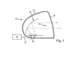
- FIG. 1 shows a lighting device 10 of a motor vehicle in a longitudinal section.
- the lighting device 10 may be formed as a headlight or as a lamp and may generate one or more light functions, such as high beam, low beam and / or fog light in a headlight or position light, flashing light and / or daytime running lights in a bowling or brake light, tail light Flashing light, position light and / or reversing light in a tail light.
- the lighting device 10 may also be designed for the realization of both headlight and lamp functions.
- the lighting device 10 is formed as a motor vehicle headlight.
- the illumination device 10 comprises a housing 12, which in a light exit direction 14 has a light exit opening closed by a light-permeable cover 16.
- two semiconductor light sources 18, in particular two light emitting diodes (LEDs) are arranged by way of example.
- the semiconductor light sources 18 could also be assigned in each case additionally one or a common intent optics for bundling the emitted light (not shown).
- the semiconductor light sources 18 are preferably operated by means of a pulse width modulated (PWM) signal. By varying a duty cycle of the PWM signal, the power of the LEDs 18 and thus their waste heat and brightness can be changed.
- PWM pulse width modulated
- the PWM signal is provided by a controller 20 and supplied to the LEDs 18 via a signal line 22.
- the control unit 20 is supplied via an electrical system of the motor vehicle, in particular of a vehicle battery, with electrical energy (not shown).
- the controller 20 is responsible for the operation of the LEDs 18. In this case, the controller 20 may determine the PWM signal regulated or controlled.
- the control unit 20 is arranged outside of the headlight housing 12 in the illustrated embodiment. It is also conceivable that it is arranged at any point within the housing 12.
- the headlight 10 has a reflector 24, which is formed in the illustrated embodiment as a half-shell reflector.
- the light-emitting diodes 18 are arranged below the half-shell reflector 24.
- the light emitted by the LEDs 18 and reflected by the reflector 24 leaves the headlight 10 through the cover 16 and arrives at a roadway in front of the vehicle to produce a desired distribution of light.
- a diaphragm arrangement (not shown) could be arranged in the beam path of the emitted and / or reflected light for generating or supporting the generation of a substantially horizontal light-dark boundary on the roadway in front of the vehicle.
- the in FIG. 1 shown headlight 10 works on the reflection principle.
- the lighting device 10 could also be designed as a working according to a projection principle headlight.
- a projection lens would be provided in the beam path of the reflected light, which images the reflected light to produce a desired light distribution on the road ahead of the vehicle.
- a diaphragm arrangement can be arranged between the reflector and the projection lens, with the lens projecting an upper edge (in the case of a vertical diaphragm arrangement) or a leading edge (with a horizontally positioned diaphragm arrangement) onto the roadway as a light-dark boundary.
- FIG. 2 shows a schematic view of a lighting device 10 with an integrated control unit 20.
- the control unit 20 is supplied via supply lines 28 of the vehicle electrical system with electrical energy.
- the controller 20 vorgesgt For example, via a computing device 30, for example.
- a computing device 30 for example.
- the computer program is programmed to execute the method according to the invention when it runs on the processor 30.
- the computer program for generating a pulse width modulated signal and for driving the semiconductor light sources 18 is programmed with the PWM signal.
- the PWM signal can be varied in particular with regard to the period duration (ie the frequency) and the pulse duration (and thus the duty cycle).
- the PWM signal is preferably an operating current I of the semiconductor light sources 18.
- the control unit 20 or the computer program running on the processor 30 can also specify an operating mode of the semiconductor light sources 18. This includes a normal operation and a different from the normal operation diagnostic operation. In the diagnostic mode, a diagnosis of the semiconductor light sources, for example, a check of current and voltage values for plausibility to detect short circuits, battery failures or line breaks executed. As a result, basic operation functions of the semiconductor light sources 18 can be ensured. During the entire duration of the diagnosis, the semiconductor light sources 18 are continuously energized.
- the operating module for the diagnosis of the semiconductor light sources 18 In order to be able to realize a complete diagnosis even without a light flare or a lightning-like effect of the semiconductor light sources 18, it is proposed according to the present invention to switch the operating module for the diagnosis of the semiconductor light sources 18 into a special diagnostic operation. This differs from normal operation at least by that it has a longer period.
- the duty cycle of the PWM signal during the diagnostic operation is preferably approximately the same size (at most twice as large) as in normal operation, so that light flashes are avoided during the diagnostic operation. However, it is also conceivable that the duty cycle in the diagnostic mode significantly greater than (at least three times as large as) in normal operation, so that deliberately light flashes are caused during diagnostic operation.
- the pulse duration during the diagnostic operation is preferably selected so long that the entire diagnosis can be carried out during the pulse duration. By selecting the subsequent pulse gap, the duty cycle can be set during diagnostic operation.
- the diagnosis is preferably performed at the beginning of each turn-on of the semiconductor light sources 18.
- switching on can be understood as meaning the operation of a switching element (for example a light switch, a brake pedal switch or a flashing light switch) by the driver.
- this can be understood as an automatic periodic switching on of the semiconductor light sources 18, for example by means of a flashing light relay.
- a switching element for example a light switch, a brake pedal switch or a flashing light switch
- this can be understood as an automatic periodic switching on of the semiconductor light sources 18, for example by means of a flashing light relay.
- the time to switch to diagnostic mode can be selected time-controlled or event-controlled.
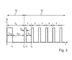
- a preferred embodiment of the method is based on a in FIG. 3 illustrated exemplary temporal
- the diagnostic operation 32 includes only a single period of duration T 0 with a pulse of duration T E0 and a pulse gap of duration T P0 .
- the diagnosis of the semiconductor light sources 18 is performed.
- the diagnostic operation 32 is followed by the normal operation 34 of the semiconductor light source 18, with repetitive periods of duration T, each comprising a pulse of duration T E and a pulse gap of duration T P. It is based on the FIG. 3 clearly recognizes that the period T 0 during the diagnostic operation 32 is longer than the period T during normal operation 34.
- T 0 T e ⁇ 0 + T P ⁇ 0 f ⁇ u ⁇ ⁇ r the diagnostic mode 32nd
- the semiconductor light sources 18 can be operated in the method according to the invention in dependence on the current operating mode with two different frequencies f 0 and f, wherein the frequency f 0 in the diagnostic mode 32 is smaller than the frequency f in normal operation 34th
- the duty cycle d 0 of the pulse width modulated signal I during the diagnostic operation 32 is ideally and therefore preferable to select the duty cycle d 0 of the pulse width modulated signal I during the diagnostic operation 32 to be the same as the duty cycle d during the normal operation 34.
- the frequency f 0 is lowered or the period duration T 0 is extended by the pulse duration T E0 (eg, approximately 5 ms), which is essentially predetermined due to the required diagnostic duration.
- the duty cycle d 0 of the pulse width modulated signal I during the diagnostic operation 32 may deviate from this ideal case, but should be selected at least in the range of the duty cycle d in normal operation 34 of the semiconductor light source 18 to ensure the suppression of the lightning-like effect.
- the frequency f 0 should not be reduced so much that the frequency f 0 falls below a cutoff frequency of a dynamic, visual sensitivity of the human eye. Otherwise, the human eye would be the (relatively slow) fluctuations between pulse and pulse gap perceive as a disturbing light flicker.
- the cutoff frequency is around 50 Hz.
- the frequency f 0 for the diagnostic mode 32 must be limited by selecting a correspondingly shorter pulse gap T P0 , The duty ratio d 0 then deviates from the duty ratio d.
- the frequency f 0 should be set exactly to f omin , so that the deviation of the two duty cycles d 0 and d is as small as possible.
- the frequency f 0 is limited, for example to f 0min , which corresponds to a pulse gap T P0 of 16 ms.
- the duty cycle d 0 of the diagnostic operation 32 must be significantly greater than the duty ratio d in normal operation 34.
- the increased duty ratio d 0 can be achieved either by extending the pulse duration T E0 or by shortening the pulse gap T P0 or by a combination of both measures ,
- any desired duty ratio d 0 can be set.
- a first example shows method steps with shortening of the pulse gap T P0 .
- a second example shows process steps with extension of the pulse duration T E0 without limiting the pulse gap T P0 .
- An essential aspect of the present invention is not to be seen in the fact that the duty ratio d 0 in the diagnostic mode 32 in a certain ratio to the duty cycle d in normal operation 34, but rather is that it is possible for the first time by the invention, the duty ratio d 0 or to set the pulse duration T E0 during the diagnostic operation 32 of a semiconductor light source 18 operated with a PWM signal I virtually as desired. As a result, a particularly simple and flexible diagnosis of the semiconductor light source 18 is possible.
- a third example shows method steps with extension of the pulse duration T E0 with limitation in order not to fall below the frequency f 0min .
- the duty ratio d 0 is so high that a noticeable lightning-like effect is perceptible.
- T E0 4 ms
- a too small duty cycle d 0 would result for the diagnostic operation 32, whereby a lightning-like effect would hardly be perceptible.
- a fourth example shows process steps with extension of the pulse duration T E0 combined with a shortening of the pulse gap T P0 .
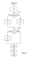
- FIG. 4 shows a flowchart of the method according to the invention according to a preferred embodiment.
- the individual method steps can be programmed in a computer program, wherein the computer program can be executable on a computing device 30 in the control unit 20.
- a step 100 the driver of the motor vehicle actuates a switching element for activating a desired light function.
- a necessary light intensity of the illumination device 10 and thus also a mean operating current I of the semiconductor light sources 18 for normal operation 34 are fixed.
- the duty ratio d of the PWM signal I for the operation of the semiconductor light sources 18 of the illumination device 10 is given.
- the diagnosis of the semiconductor light source 18 in the diagnostic mode 32 is performed.
- the normal operation 34 is interrupted at any time by the diagnostic operation 32.
- the frequency f 0 in the diagnostic mode 32 differs from the frequency f in normal operation 34 as a rule, in particular the frequency f 0 is selected to be lower.
- the duty cycle d 0 in diagnostic mode 32 (step 120) is chosen to be significantly greater than the duty cycle d during normal operation 34. This can be achieved either by an extension of the pulse duration T E0 or by a shortening of the pulse gap T P0 in FIG Diagnostic operation or by a combination of both measures can be achieved.
- a query block 140 determines whether the frequency f 0 calculated for the diagnostic operation 32 is less than the minimum frequency f 0min (eg about 50 Hz). If this is the case, in a step 150 the pulse gap T P0 is preferably reduced so far that thereafter the minimum frequency f 0min and thus also a maximum period duration T 0 for the diagnostic mode 32 are set. Subsequently, in a step 160, the diagnosis of the semiconductor light sources 18 is carried out during the determined pulse duration T E0 . Finally, in a step 170, the operating mode of the semiconductor light sources 18 is switched to the normal mode 34.
- the minimum frequency f 0min eg about 50 Hz
Landscapes
- Engineering & Computer Science (AREA)
- Mechanical Engineering (AREA)
- Lighting Device Outwards From Vehicle And Optical Signal (AREA)
Applications Claiming Priority (1)
| Application Number | Priority Date | Filing Date | Title |
|---|---|---|---|
| DE102010064220A DE102010064220A1 (de) | 2010-12-27 | 2010-12-27 | Verfahren zum Betreiben einer Beleuchtungseinrichtung eines Fahrzeugs |
Publications (2)
| Publication Number | Publication Date |
|---|---|
| EP2468570A1 true EP2468570A1 (fr) | 2012-06-27 |
| EP2468570B1 EP2468570B1 (fr) | 2016-03-02 |
Family
ID=45540736
Family Applications (1)
| Application Number | Title | Priority Date | Filing Date |
|---|---|---|---|
| EP11192732.3A Active EP2468570B1 (fr) | 2010-12-27 | 2011-12-09 | Procédé de fonctionnement d'un dispositif d'éclairage d'un véhicule |
Country Status (2)
| Country | Link |
|---|---|
| EP (1) | EP2468570B1 (fr) |
| DE (1) | DE102010064220A1 (fr) |
Cited By (2)
| Publication number | Priority date | Publication date | Assignee | Title |
|---|---|---|---|---|
| EP2882260A1 (fr) * | 2013-12-03 | 2015-06-10 | Contronix GmbH | Circuit de protection pour la surveillance d'installations d'éclairage |
| DE102013020753A1 (de) | 2013-12-11 | 2015-06-11 | Audi Ag | Verfahren und Vorrichtung zum Überprüfen einer Funktionsfähigkeit einer Beleuchtungseinrichtung einer Kraftfahrzeugaußenbeleuchtung |
Families Citing this family (1)
| Publication number | Priority date | Publication date | Assignee | Title |
|---|---|---|---|---|
| DE102020104959A1 (de) | 2020-02-26 | 2021-08-26 | HELLA GmbH & Co. KGaA | Verfahren und Vorrichtung zur automatisierten Detektion einer Beeinträchtigung einer Lichtabstrahlung bei einer Beleuchtungsvorrichtung für ein Fahrzeug |
Citations (3)
| Publication number | Priority date | Publication date | Assignee | Title |
|---|---|---|---|---|
| DE102005051212A1 (de) * | 2005-10-26 | 2007-05-03 | Bayerische Motoren Werke Ag | Verfahren zur Überwachung der Funktion eines Leuchtkörpers |
| EP2080667A1 (fr) * | 2008-01-18 | 2009-07-22 | ASPÖCK Systems GmbH | Procédé destiné au contrôle d'extinction des fonctions lumineuses dans un réseau à bord de véhicule automobile |
| DE102008047731A1 (de) * | 2008-09-18 | 2010-03-25 | Hella Kgaa Hueck & Co. | Verfahren zur Fehlererkennung in einer Beleuchtungsvorrichtung |
-
2010
- 2010-12-27 DE DE102010064220A patent/DE102010064220A1/de not_active Ceased
-
2011
- 2011-12-09 EP EP11192732.3A patent/EP2468570B1/fr active Active
Patent Citations (3)
| Publication number | Priority date | Publication date | Assignee | Title |
|---|---|---|---|---|
| DE102005051212A1 (de) * | 2005-10-26 | 2007-05-03 | Bayerische Motoren Werke Ag | Verfahren zur Überwachung der Funktion eines Leuchtkörpers |
| EP2080667A1 (fr) * | 2008-01-18 | 2009-07-22 | ASPÖCK Systems GmbH | Procédé destiné au contrôle d'extinction des fonctions lumineuses dans un réseau à bord de véhicule automobile |
| DE102008047731A1 (de) * | 2008-09-18 | 2010-03-25 | Hella Kgaa Hueck & Co. | Verfahren zur Fehlererkennung in einer Beleuchtungsvorrichtung |
Cited By (2)
| Publication number | Priority date | Publication date | Assignee | Title |
|---|---|---|---|---|
| EP2882260A1 (fr) * | 2013-12-03 | 2015-06-10 | Contronix GmbH | Circuit de protection pour la surveillance d'installations d'éclairage |
| DE102013020753A1 (de) | 2013-12-11 | 2015-06-11 | Audi Ag | Verfahren und Vorrichtung zum Überprüfen einer Funktionsfähigkeit einer Beleuchtungseinrichtung einer Kraftfahrzeugaußenbeleuchtung |
Also Published As
| Publication number | Publication date |
|---|---|
| EP2468570B1 (fr) | 2016-03-02 |
| DE102010064220A1 (de) | 2012-06-28 |
Similar Documents
| Publication | Publication Date | Title |
|---|---|---|
| DE102007058536A1 (de) | Verfahren zum Verringern der Helligkeitsabgabe von Leuchtmitteln und Vorrichtung zum Vermindern der Helligkeit von Leuchtmitteln bei Fahrzeugen | |
| EP2596992A2 (fr) | Eclairage de véhicule automobile, véhicule automobile et procédé de fonctionnement d'un éclairage de véhicule automobile | |
| DE102005000807A1 (de) | Beleuchtungsvorrichtungs-Steuergerät für Fahrzeuge | |
| EP3010759B1 (fr) | Procédé et dispositif pour la commande d'une émission de lumière d'un feu arrière d'un véhicule | |
| EP2261081A1 (fr) | Procédé destiné au fonctionnement d'un dispositif d'éclairage | |
| DE102016206275A1 (de) | Verfahren zum Betreiben wenigstens einer Beleuchtungsvorrichtung eines stillstehenden Kraftfahrzeugs | |
| DE102012023786A1 (de) | Scheinwerferanordnung für ein Kraftfahrzeug | |
| EP2468570B1 (fr) | Procédé de fonctionnement d'un dispositif d'éclairage d'un véhicule | |
| DE202013011958U1 (de) | Dynamisches Tagfahrlicht | |
| DE102011051152A1 (de) | Verfahren zum Betrieb einer Leuchte sowie Leuchte für ein Fahrzeug | |
| DE102010050851A1 (de) | Verfahren zum Steuern der Helligkeit von Halbleiterlichtquellen eines Kraftfahrzeug und korrespondierende Vorrichtungen | |
| EP1594346A2 (fr) | Méthode de contrôle d'un clignotant de voiture | |
| DE102008023338A1 (de) | Beleuchtungseinrichtung für ein Kraftfahrzeug | |
| DE102011115670A1 (de) | Verfahren zum Betreiben eines Fahrerassistenzsystems und Fahrerassistenzsystem | |
| DE102008021688A1 (de) | Außenbeleuchtungsgruppe für ein Fahrzeug | |
| EP2918446A1 (fr) | Système et procédé de commande d'un phare de véhicule | |
| EP2050619A2 (fr) | Dispositif et procédé d'émission d'un paramètre de fonctionnement d'au moins un moyen d'éclairage d'une source lumineuse d'un véhicule automobile | |
| DE102017129291A1 (de) | Beleuchtungseinrichtung eines Kraftfahrzeugs mit matrixartig angeordneten Leuchtdioden und Verfahren zum Betreiben von matrixartig angeordneten Leuchtdioden einer solchen Beleuchtungseinrichtung | |
| EP1275556B1 (fr) | Dispositif pour réduire l'éblouissement d'un conducteur de véhicule | |
| EP3636491A1 (fr) | Lampe de véhicule et son procédé de fonctionnement | |
| DE102010006636A1 (de) | Lichtschaltverfahren zur Steuerung der Lichtabgabe von Fahrzeugen | |
| DE102007009078A1 (de) | Scheinwerfer für ein Fahrzeug mit einer als Leuchtdiode ausgebildeten Lichtquelle mit Lichthupenfunktion | |
| EP4051955B1 (fr) | Procédé de fonctionnement d'un feu arrière d'un véhicule à moteur et véhicule automobile | |
| EP3442312A1 (fr) | Procédé d'éclairage d'un espace intérieur d'un véhicule automobile ainsi que vehicule automobile | |
| EP2173585B1 (fr) | Système d'éclairage pour véhicule automobile |
Legal Events
| Date | Code | Title | Description |
|---|---|---|---|
| AK | Designated contracting states |
Kind code of ref document: A1 Designated state(s): AL AT BE BG CH CY CZ DE DK EE ES FI FR GB GR HR HU IE IS IT LI LT LU LV MC MK MT NL NO PL PT RO RS SE SI SK SM TR |
|
| AX | Request for extension of the european patent |
Extension state: BA ME |
|
| PUAI | Public reference made under article 153(3) epc to a published international application that has entered the european phase |
Free format text: ORIGINAL CODE: 0009012 |
|
| 17P | Request for examination filed |
Effective date: 20121213 |
|
| 17Q | First examination report despatched |
Effective date: 20140220 |
|
| GRAP | Despatch of communication of intention to grant a patent |
Free format text: ORIGINAL CODE: EPIDOSNIGR1 |
|
| INTG | Intention to grant announced |
Effective date: 20150803 |
|
| GRAS | Grant fee paid |
Free format text: ORIGINAL CODE: EPIDOSNIGR3 |
|
| GRAA | (expected) grant |
Free format text: ORIGINAL CODE: 0009210 |
|
| AK | Designated contracting states |
Kind code of ref document: B1 Designated state(s): AL AT BE BG CH CY CZ DE DK EE ES FI FR GB GR HR HU IE IS IT LI LT LU LV MC MK MT NL NO PL PT RO RS SE SI SK SM TR |
|
| REG | Reference to a national code |
Ref country code: GB Ref legal event code: FG4D Free format text: NOT ENGLISH |
|
| REG | Reference to a national code |
Ref country code: AT Ref legal event code: REF Ref document number: 777773 Country of ref document: AT Kind code of ref document: T Effective date: 20160315 Ref country code: CH Ref legal event code: EP |
|
| REG | Reference to a national code |
Ref country code: IE Ref legal event code: FG4D Free format text: LANGUAGE OF EP DOCUMENT: GERMAN |
|
| GRAT | Correction requested after decision to grant or after decision to maintain patent in amended form |
Free format text: ORIGINAL CODE: EPIDOSNCDEC |
|
| REG | Reference to a national code |
Ref country code: DE Ref legal event code: R096 Ref document number: 502011008975 Country of ref document: DE |
|
| REG | Reference to a national code |
Ref country code: NL Ref legal event code: MP Effective date: 20160302 |
|
| REG | Reference to a national code |
Ref country code: LT Ref legal event code: MG4D |
|
| PG25 | Lapsed in a contracting state [announced via postgrant information from national office to epo] |
Ref country code: NO Free format text: LAPSE BECAUSE OF FAILURE TO SUBMIT A TRANSLATION OF THE DESCRIPTION OR TO PAY THE FEE WITHIN THE PRESCRIBED TIME-LIMIT Effective date: 20160602 Ref country code: GR Free format text: LAPSE BECAUSE OF FAILURE TO SUBMIT A TRANSLATION OF THE DESCRIPTION OR TO PAY THE FEE WITHIN THE PRESCRIBED TIME-LIMIT Effective date: 20160603 Ref country code: FI Free format text: LAPSE BECAUSE OF FAILURE TO SUBMIT A TRANSLATION OF THE DESCRIPTION OR TO PAY THE FEE WITHIN THE PRESCRIBED TIME-LIMIT Effective date: 20160302 Ref country code: ES Free format text: LAPSE BECAUSE OF FAILURE TO SUBMIT A TRANSLATION OF THE DESCRIPTION OR TO PAY THE FEE WITHIN THE PRESCRIBED TIME-LIMIT Effective date: 20160302 Ref country code: HR Free format text: LAPSE BECAUSE OF FAILURE TO SUBMIT A TRANSLATION OF THE DESCRIPTION OR TO PAY THE FEE WITHIN THE PRESCRIBED TIME-LIMIT Effective date: 20160302 |
|
| PG25 | Lapsed in a contracting state [announced via postgrant information from national office to epo] |
Ref country code: NL Free format text: LAPSE BECAUSE OF FAILURE TO SUBMIT A TRANSLATION OF THE DESCRIPTION OR TO PAY THE FEE WITHIN THE PRESCRIBED TIME-LIMIT Effective date: 20160302 Ref country code: RS Free format text: LAPSE BECAUSE OF FAILURE TO SUBMIT A TRANSLATION OF THE DESCRIPTION OR TO PAY THE FEE WITHIN THE PRESCRIBED TIME-LIMIT Effective date: 20160302 Ref country code: LV Free format text: LAPSE BECAUSE OF FAILURE TO SUBMIT A TRANSLATION OF THE DESCRIPTION OR TO PAY THE FEE WITHIN THE PRESCRIBED TIME-LIMIT Effective date: 20160302 Ref country code: LT Free format text: LAPSE BECAUSE OF FAILURE TO SUBMIT A TRANSLATION OF THE DESCRIPTION OR TO PAY THE FEE WITHIN THE PRESCRIBED TIME-LIMIT Effective date: 20160302 Ref country code: PL Free format text: LAPSE BECAUSE OF FAILURE TO SUBMIT A TRANSLATION OF THE DESCRIPTION OR TO PAY THE FEE WITHIN THE PRESCRIBED TIME-LIMIT Effective date: 20160302 Ref country code: SE Free format text: LAPSE BECAUSE OF FAILURE TO SUBMIT A TRANSLATION OF THE DESCRIPTION OR TO PAY THE FEE WITHIN THE PRESCRIBED TIME-LIMIT Effective date: 20160302 |
|
| PG25 | Lapsed in a contracting state [announced via postgrant information from national office to epo] |
Ref country code: IS Free format text: LAPSE BECAUSE OF FAILURE TO SUBMIT A TRANSLATION OF THE DESCRIPTION OR TO PAY THE FEE WITHIN THE PRESCRIBED TIME-LIMIT Effective date: 20160702 Ref country code: EE Free format text: LAPSE BECAUSE OF FAILURE TO SUBMIT A TRANSLATION OF THE DESCRIPTION OR TO PAY THE FEE WITHIN THE PRESCRIBED TIME-LIMIT Effective date: 20160302 |
|
| REG | Reference to a national code |
Ref country code: FR Ref legal event code: PLFP Year of fee payment: 6 |
|
| PG25 | Lapsed in a contracting state [announced via postgrant information from national office to epo] |
Ref country code: SK Free format text: LAPSE BECAUSE OF FAILURE TO SUBMIT A TRANSLATION OF THE DESCRIPTION OR TO PAY THE FEE WITHIN THE PRESCRIBED TIME-LIMIT Effective date: 20160302 Ref country code: PT Free format text: LAPSE BECAUSE OF FAILURE TO SUBMIT A TRANSLATION OF THE DESCRIPTION OR TO PAY THE FEE WITHIN THE PRESCRIBED TIME-LIMIT Effective date: 20160704 Ref country code: RO Free format text: LAPSE BECAUSE OF FAILURE TO SUBMIT A TRANSLATION OF THE DESCRIPTION OR TO PAY THE FEE WITHIN THE PRESCRIBED TIME-LIMIT Effective date: 20160302 Ref country code: SM Free format text: LAPSE BECAUSE OF FAILURE TO SUBMIT A TRANSLATION OF THE DESCRIPTION OR TO PAY THE FEE WITHIN THE PRESCRIBED TIME-LIMIT Effective date: 20160302 Ref country code: CZ Free format text: LAPSE BECAUSE OF FAILURE TO SUBMIT A TRANSLATION OF THE DESCRIPTION OR TO PAY THE FEE WITHIN THE PRESCRIBED TIME-LIMIT Effective date: 20160302 |
|
| REG | Reference to a national code |
Ref country code: DE Ref legal event code: R097 Ref document number: 502011008975 Country of ref document: DE |
|
| PLBE | No opposition filed within time limit |
Free format text: ORIGINAL CODE: 0009261 |
|
| STAA | Information on the status of an ep patent application or granted ep patent |
Free format text: STATUS: NO OPPOSITION FILED WITHIN TIME LIMIT |
|
| PG25 | Lapsed in a contracting state [announced via postgrant information from national office to epo] |
Ref country code: DK Free format text: LAPSE BECAUSE OF FAILURE TO SUBMIT A TRANSLATION OF THE DESCRIPTION OR TO PAY THE FEE WITHIN THE PRESCRIBED TIME-LIMIT Effective date: 20160302 |
|
| 26N | No opposition filed |
Effective date: 20161205 |
|
| PG25 | Lapsed in a contracting state [announced via postgrant information from national office to epo] |
Ref country code: BG Free format text: LAPSE BECAUSE OF FAILURE TO SUBMIT A TRANSLATION OF THE DESCRIPTION OR TO PAY THE FEE WITHIN THE PRESCRIBED TIME-LIMIT Effective date: 20160602 Ref country code: SI Free format text: LAPSE BECAUSE OF FAILURE TO SUBMIT A TRANSLATION OF THE DESCRIPTION OR TO PAY THE FEE WITHIN THE PRESCRIBED TIME-LIMIT Effective date: 20160302 |
|
| PG25 | Lapsed in a contracting state [announced via postgrant information from national office to epo] |
Ref country code: BE Free format text: LAPSE BECAUSE OF NON-PAYMENT OF DUE FEES Effective date: 20161231 |
|
| REG | Reference to a national code |
Ref country code: CH Ref legal event code: PL |
|
| PG25 | Lapsed in a contracting state [announced via postgrant information from national office to epo] |
Ref country code: MC Free format text: LAPSE BECAUSE OF FAILURE TO SUBMIT A TRANSLATION OF THE DESCRIPTION OR TO PAY THE FEE WITHIN THE PRESCRIBED TIME-LIMIT Effective date: 20160302 |
|
| REG | Reference to a national code |
Ref country code: IE Ref legal event code: MM4A |
|
| PG25 | Lapsed in a contracting state [announced via postgrant information from national office to epo] |
Ref country code: CH Free format text: LAPSE BECAUSE OF NON-PAYMENT OF DUE FEES Effective date: 20161231 Ref country code: LU Free format text: LAPSE BECAUSE OF NON-PAYMENT OF DUE FEES Effective date: 20161209 Ref country code: LI Free format text: LAPSE BECAUSE OF NON-PAYMENT OF DUE FEES Effective date: 20161231 |
|
| REG | Reference to a national code |
Ref country code: FR Ref legal event code: PLFP Year of fee payment: 7 |
|
| PG25 | Lapsed in a contracting state [announced via postgrant information from national office to epo] |
Ref country code: IE Free format text: LAPSE BECAUSE OF NON-PAYMENT OF DUE FEES Effective date: 20161209 |
|
| REG | Reference to a national code |
Ref country code: BE Ref legal event code: MM Effective date: 20161231 |
|
| REG | Reference to a national code |
Ref country code: AT Ref legal event code: MM01 Ref document number: 777773 Country of ref document: AT Kind code of ref document: T Effective date: 20161209 |
|
| PG25 | Lapsed in a contracting state [announced via postgrant information from national office to epo] |
Ref country code: AT Free format text: LAPSE BECAUSE OF NON-PAYMENT OF DUE FEES Effective date: 20161209 Ref country code: CY Free format text: LAPSE BECAUSE OF FAILURE TO SUBMIT A TRANSLATION OF THE DESCRIPTION OR TO PAY THE FEE WITHIN THE PRESCRIBED TIME-LIMIT Effective date: 20160302 Ref country code: HU Free format text: LAPSE BECAUSE OF FAILURE TO SUBMIT A TRANSLATION OF THE DESCRIPTION OR TO PAY THE FEE WITHIN THE PRESCRIBED TIME-LIMIT; INVALID AB INITIO Effective date: 20111209 |
|
| PG25 | Lapsed in a contracting state [announced via postgrant information from national office to epo] |
Ref country code: MK Free format text: LAPSE BECAUSE OF FAILURE TO SUBMIT A TRANSLATION OF THE DESCRIPTION OR TO PAY THE FEE WITHIN THE PRESCRIBED TIME-LIMIT Effective date: 20160302 Ref country code: TR Free format text: LAPSE BECAUSE OF FAILURE TO SUBMIT A TRANSLATION OF THE DESCRIPTION OR TO PAY THE FEE WITHIN THE PRESCRIBED TIME-LIMIT Effective date: 20160302 |
|
| PG25 | Lapsed in a contracting state [announced via postgrant information from national office to epo] |
Ref country code: MT Free format text: LAPSE BECAUSE OF FAILURE TO SUBMIT A TRANSLATION OF THE DESCRIPTION OR TO PAY THE FEE WITHIN THE PRESCRIBED TIME-LIMIT Effective date: 20160302 |
|
| PG25 | Lapsed in a contracting state [announced via postgrant information from national office to epo] |
Ref country code: AL Free format text: LAPSE BECAUSE OF FAILURE TO SUBMIT A TRANSLATION OF THE DESCRIPTION OR TO PAY THE FEE WITHIN THE PRESCRIBED TIME-LIMIT Effective date: 20160302 |
|
| PGFP | Annual fee paid to national office [announced via postgrant information from national office to epo] |
Ref country code: GB Payment date: 20181127 Year of fee payment: 8 |
|
| GBPC | Gb: european patent ceased through non-payment of renewal fee |
Effective date: 20191209 |
|
| PG25 | Lapsed in a contracting state [announced via postgrant information from national office to epo] |
Ref country code: GB Free format text: LAPSE BECAUSE OF NON-PAYMENT OF DUE FEES Effective date: 20191209 |
|
| P01 | Opt-out of the competence of the unified patent court (upc) registered |
Effective date: 20230508 |
|
| PGFP | Annual fee paid to national office [announced via postgrant information from national office to epo] |
Ref country code: FR Payment date: 20241121 Year of fee payment: 14 |
|
| PGFP | Annual fee paid to national office [announced via postgrant information from national office to epo] |
Ref country code: IT Payment date: 20241121 Year of fee payment: 14 |
|
| REG | Reference to a national code |
Ref country code: DE Ref legal event code: R084 Ref document number: 502011008975 Country of ref document: DE |
|
| PGFP | Annual fee paid to national office [announced via postgrant information from national office to epo] |
Ref country code: DE Payment date: 20251126 Year of fee payment: 15 |
|
| REG | Reference to a national code |
Ref country code: DE Ref legal event code: R081 Ref document number: 502011008975 Country of ref document: DE Owner name: MARELLI GERMANY GMBH, DE Free format text: FORMER OWNER: AUTOMOTIVE LIGHTING REUTLINGEN GMBH, 72762 REUTLINGEN, DE |