EP2468627A1 - Luftfahrzeug, das mit einem rückseitigen Kipprotor ausgestattet ist, und entsprechendes Verfahren - Google Patents
Luftfahrzeug, das mit einem rückseitigen Kipprotor ausgestattet ist, und entsprechendes Verfahren Download PDFInfo
- Publication number
- EP2468627A1 EP2468627A1 EP11009514A EP11009514A EP2468627A1 EP 2468627 A1 EP2468627 A1 EP 2468627A1 EP 11009514 A EP11009514 A EP 11009514A EP 11009514 A EP11009514 A EP 11009514A EP 2468627 A1 EP2468627 A1 EP 2468627A1
- Authority
- EP
- European Patent Office
- Prior art keywords
- aircraft
- rotor
- rotary wing
- mast
- mode
- Prior art date
- Legal status (The legal status is an assumption and is not a legal conclusion. Google has not performed a legal analysis and makes no representation as to the accuracy of the status listed.)
- Granted
Links
Images


Classifications
-
- B—PERFORMING OPERATIONS; TRANSPORTING
- B64—AIRCRAFT; AVIATION; COSMONAUTICS
- B64C—AEROPLANES; HELICOPTERS
- B64C27/00—Rotorcraft; Rotors peculiar thereto
- B64C27/82—Rotorcraft; Rotors peculiar thereto characterised by the provision of an auxiliary rotor or fluid-jet device for counter-balancing lifting rotor torque or changing direction of rotorcraft
Definitions
- the present invention relates to a method of piloting a rotary wing aircraft provided with a rear rotor adapted to pivot about a tilting axis, as well as such an aircraft.
- the invention relates to aircraft equipped on the one hand with a rotary wing to at least partially ensure the lift of the aircraft and, on the other hand, with a rear rotor adapted to counter the yaw torque generated. by the rotary wing on the airframe of the aircraft, this rear rotor being pivotable about an axis to contribute to the propulsion of the aircraft.
- the performance of a helicopter is typically limited by the rotational speed of the main rotor constituting the rotary wing.
- the relative speed of the blades of this main rotor relative to the surrounding air must especially be locally lower than the speed of sound.
- the service life of the components is notably reduced because of the appearance of vibrations and because of the stresses introduced by the mast-shaped torsor generated by the cyclic pitch.
- the document FR 1 511 006 suggests the use of a caudal propellant propeller associated with the conventional rear anti-torque rotor of a helicopter.
- the caudal propeller then allows to discharge the main rotor of at least a portion of its propulsive function.
- the document FR1,017,976 suggests using an aircraft equipped with a rotary wing and a rear rotor capable of pivoting about a tilting axis.
- the rear rotor is in a first position in order to counter the torque generated by the rotary wing and to control the yaw movement of the aircraft.
- the rear rotor switches to a second position to participate in the propulsion of the aircraft, the yaw control being obtained by orienting the rear rotor on either side of a neutral location.
- the first position is qualified for convenience in the remainder of the text of "first fixed position” insofar as the rear rotor is fixed in a predetermined position during the primary operating mode, the aircraft then operating as a conventional helicopter .
- the second position is described for convenience in the following text "second steerable position" in that the rear rotor moves in a predetermined angular sector during the secondary mode of operation.
- Such an aircraft is sometimes referred to as a "vector-driven helicopter".
- the document GB 599 990 also presents an aircraft of this type.
- the document US 3,155,341 presents a convertiplane equipped with a main rotor, a tilting rear rotor and a wing adapted to pass from a helicopter mode to an airplane mode.
- the convertiplane is not an aircraft with vector thrust, the lifter being disconnected from the rear rotor in forward flight.
- the document FR 1 536 412 presents a control mechanism for pivoting a rear rotor of a convertiplane.
- This mechanism comprises a single output relating to the pitch control of the rear rotor blades and two inputs for the yaw control in helicopter mode and the thrust control in airplane mode, the transition from one command to the other operating in a progressive way.
- the yaw control becomes inoperative while during the primary operating mode the thrust control is inoperative.
- the present invention therefore aims to provide a rotary wing aircraft capable of moving at high speed while being environmentally friendly in terms of fuel consumption and such a method of piloting such an aircraft.
- the technological background includes documents US 2004/232280 , FR 2,831,933 , FR2 831 934 , FR 2,831,938 , FR 2 842 271 , WO 2009/102739 , US 2005/045762 , FR 1017976 .
- the document US 2004/232280 presents an aircraft provided with a cell extending along an anteroposterior longitudinal plane, the cell carrying a rotary wing and a rear rotor.
- the tail rotor exerts thrust in a fixed direction included in the anteroposterior longitudinal plane to propel the aircraft.
- the mast carrying the rotary wing can be inclined towards the rear of the aircraft.
- Such an aircraft is not a vector-driven aircraft since the tail rotor is not steerable to control the yaw movement of this aircraft.
- the documents FR 2,831,933 , FR2 831 934 and FR 2 842 271 have tipping power transmission boxes, the document FR 2,831,938
- a subject of the invention is a lubrication system for a tilting power transmission.
- an aircraft is provided with a cell extending from a rear end to a front end along an anteroposterior longitudinal plane, the cell carrying a rotary wing and a rear rotor which is pivotable for be in a first fixed position in which the tail rotor is used to control the yaw movement of the aircraft or in a second steerable position during which the tail rotor pivots about a tilt axis to control yaw and at least partially control the propulsion of the aircraft, the aircraft operating in a first mode of operation when the rear rotor is in said first position.
- the aircraft has a power plant driving the rotary wing through a power transmission gearbox integral with a rotary wing drive mast, this power plant driving the tail rotor through a power rear gearbox.
- the power train must be designed in such a way that the power required by the rear rotor does not pass through the main gearbox.
- this aircraft can operate in three distinct modes, a first mode of operation during which the aircraft operates as a conventional helicopter, a second mode of operation during which the aircraft operates as a helicopter vector thrust contrary to the document US 3155341 , and a third mode of operation during which the aircraft operates substantially like a gyrocopter.
- These three modes therefore make it possible to adapt the aircraft to the environment in which it evolves according to ecological and / or performance criteria.
- the aircraft combines the advantages of three types of rotary wing rotorcraft in an unprecedented way.
- the aircraft can reach relatively high speeds with moderate fuel consumption.
- This aircraft is ecological and can travel long distances.
- the aircraft can begin its flight by changing in the first mode of operation to for example take off vertically, although the other modes can take off with a substantial speed of advance.
- the tilting means may incline the rotary wing towards the front end following a take-off inclination, for example.
- the tilting means may incline the rotary wing towards the front end following a transition inclination towards the front end having 5 ° more for example with respect to the takeoff angle of the take-off configuration, this additional inclination ensuring an increased propulsive component.
- the rear rotor is tilted by the pivoting means, on the order of the pilot or on the order of a control means requiring tilting as a function of predetermined parameters such as the speed of rotation. progress of the aircraft for example.
- the rotary wing was inclined towards the front end during an acceleration phase, the rotary wing is eventually returned to its take-off configuration so as to have the takeoff angle to limit the stresses exerted on the components of the rotary wing.
- the propulsion of the aircraft is then ensured mainly by the rear rotor.
- the aircraft is then accelerated during this second mode of operation.
- the tilting means tilts the rotary wing towards the rear end of the aircraft.
- the inclination of the rotary wing allows this rotary wing to ensure the lift of the aircraft without requiring significant power, or even without being rotated by the power plant.
- the rotary wing is disconnected from the power plant, it is possible to adapt the rotational speed of the rotary wing independently of the rotational speed of the rear rotor in propeller mode by acting on the inclination of the mast.
- the power generated by the power plant is then mainly used for the rear rotor drive related to the fact that the kinematic drive chain of the rear rotor does not pass through the main gearbox but leaves directly from the power plant, this rear rotor providing only the propulsion of the aircraft.
- the invention makes it possible to incline the rotary wing towards the rear end of the aircraft to turn the rotary wing into autorotation, which gives it a better fineness (if the rotor is flat) and allows the unloading of the wing.
- main gearbox of this rotary wing This inclination towards the rear allows optimized sizing of the main gearbox to respond to the lift function.
- the latitude offered on the tilt of the main rotor towards the rear or the front makes it possible to reduce the moments of the training mast of the rotary wing and thus to optimize the dimensioning of this mast, insofar as the main rotor is much less loaded with cyclic controls.
- This characteristic is all the more true when the aircraft is propelled by the rear rotor during the third mode of operation. This results in a reduction in the stresses exerted on the rotary wing, and consequently an increase in the lifetimes of the components and / or a weight saving compared to a conventional aircraft.
- the pivoting rear rotor providing yaw control and vector thrust in the second and third modes provides the aircraft with great maneuverability.
- the aircraft can be equipped with fixed parts allowing it to accommodate at least one wing stretching from both sides of the aircraft's cell.
- This wing provides additional lift in forward flight, can play the role of load arm for all external loads and can accommodate additional tanks to increase the range of the aircraft for example.
- the aircraft may further include one or more of the following features.
- the tilting means can act reversibly on the mast of a main rotor of the rotary wing, more simply called “mast” or “driving mast”, to incline it in the longitudinal anteroposterior to the front end of said aircraft during the first mode of operation and the second mode of operation.
- the tilting means can incline the mast towards the rear end on a first range from 0 to 5 ° for example and to the front end on a second range from 0 to 5 ° for example.
- the aircraft may comprise a first means of separation between the main power transmission gearbox and the powerplant, such as a freewheel denominated for convenience "freewheel forward" for example.
- this rotary wing when the rotary wing is inclined towards the rear end of the aircraft during the third mode of operation, this rotary wing can be set in motion only by the incident wind. All the power supplied by this power plant is then transmitted to the tail rotor.
- the freewheel front allows in particular a separation of the rotary wing vis-à-vis the power plant and the rear rotor.
- the front free wheel comprises a front drive member driven by the power plant and a front driven member driving the main gearbox.
- the free front wheel then allows the drive of the driven member before by the leading drive member.
- the aircraft may comprise a second means of separation between the rear power transmission box and the power plant, such as a freewheel referred to for convenience "freewheel rear" for example.
- the rear freewheel includes a rear driving member driven by the power plant and a rear driven member driving the power rear gearbox.
- the rear free wheel then allows the drive of the rear driven member by the rear drive member.
- the power plant may comprise at least one motor engaged with a means for sharing the power developed, the sharing means driving a main kinematic chain connected to the main power transmission gearbox, the sharing means driving a rear drivetrain connected to said rear power transmission box.
- the rotary wing and the tail rotor are each set in motion by the sharing means via a dedicated kinematic chain.
- the sharing means makes it possible to reduce the torque levels seen by the main gearbox, which allows optimized sizing of this main gearbox resulting in a gain in mass and therefore payload reinforcing the ecological character of the aircraft. .
- the front and rear freewheels mentioned above can be included in this sharing means, or be located respectively between the sharing means and the rotary wing or the rear rotor.
- the rotary wing having a plurality of first blades having a first variable pitch controlled by flight controls connected to servo actuators actuating a swashplate
- the aircraft can comprise a compensation means so that the inclination of said mast does not modify not the position of said flight controls and said servocontrols without pilot action.
- a return lever cooperates with a member affected by the tilting means to maintain in a fixed position the controls during the tilting of the rotary wing.
- the tilt means may cooperate with the main power transmission gearbox to tilt the mast carrying the rotary wing.
- the tilting means can act directly on the mast to tilt, or indirectly via the main gearbox, for example.
- the steering of the position of the rear rotor and the position of the rotary wing can be achieved by commands provided for this purpose, and 1 or possibly by a control means implementing piloting laws predetermined by the manufacturer in function by example of the mass of the aircraft, the speed of advance to reach, aerological disturbances or altitude and the outside temperature.
- the figure 1 shows a top view of an aircraft 1 according to the invention.
- the direction X represents the longitudinal axis of the aircraft schematically while another direction Y represents the transverse axis of this aircraft.
- a third direction Z is elevation and corresponds to the elevation axis of the aircraft.
- the figure 1 then presents an aircraft 1 provided with a cell 4 extending longitudinally along an anteroposterior longitudinal plane P1 of symmetry in elevation from a front end 4 'to a rear end 4. It is noted that the anteroposterior longitudinal plane P1 is defined by the longitudinal axis X and the axis in elevation Z.
- the cell 4 carries a rotary wing 2 provided with a main rotor comprising a plurality of first blades 3.
- the aircraft then has modification members of the first pitch of the first blades 3, such as a set of cyclic plates controlled by a cyclic stick adapted to vary cyclically the first pitch of the first blades 3 and a collective lever able to collectively vary the first pitch of all the first blades 3.
- the rear end 4 "of the cell 4 carries a rear rotor 10 provided with a plurality of second blades 12 rotating about an axis of rotation AX, the second pitch of the second blades 12 being modifiable.
- the rear rotor 10 may furthermore rotate about a tilting axis AX2 to move from a first fixed POS1 position represented in bold during which the tail rotor exerts a force to control the yaw movement of the aircraft, to a second position POS2 represented by the angular sector ⁇ during which the rear rotor 10 can be moved in said angular sector ⁇ to control the yaw movement of the aircraft and at least participate in the propulsion.
- the axis of rotation AX of the second blades of the rear rotor 10 is fixed, for example being orthogonal to the anteroposterior longitudinal plane P1 to counteract the yaw torque generated by the rotary wing 2 on the cell 4.
- this axis of rotation AX can rotate about the tilting axis AX2 in order to direct the air mass passing through the rear rotor 10 towards the rear of the aircraft.
- the rear rotor 10 pivots on both sides of the longitudinal anteroposterior plane P1 to participate in the propulsion of the aircraft and to control the yaw movement of the aircraft.
- the angular sector ⁇ in which the axis of rotation of the rear rotor 10 evolves varies in a range of 180 ° from the position of the rear rotor 10 shown in solid lines on the figure 1 towards the position of the rear rotor 10 shown in dashed lines on this figure 1 .
- the pilot can use a first control means such as a lifter, and a second control means, an analog push button for example.
- a first control means such as a lifter
- a second control means an analog push button for example.
- the first control means is used more precisely to modify the second pitch of the second blades 12 of the rear rotor 10.
- the pilot controls the yaw motion of the aircraft 1 by controlling the amplitude of the thrust generated by the rear rotor 10.
- the second control means 302 is deactivated for safety.
- the first control means is used to orient the rear rotor 10 with respect to the anteroposterior longitudinal plane P1, and the second control means for modifying the second pitch of the second blades 12. Therefore, the pilot always controls the yaw movement of the aircraft using the first control means, but controls the speed of advance of the aircraft using the second control means 302 in particular.
- the passage from one position to another of the rear rotor may be required by a switching means operable by the pilot or by a control means according to predetermined control laws.
- the aircraft 1 comprises a power plant 20 rotating a mast 31 carrying the rotary wing 2 through a main gearbox 30 power, this power plant 20 further rotating the rear rotor 10 to through a 40-speed power transmission.
- the aircraft 1 comprises a pivoting means 43 controlled by the rudder in the second mode to change the position of the rear rotor, the pivoting means for tilting the rear rotor of the first POS1 fixed position to a second position POS2 adjustable in a given angular sector ⁇ , and vice versa.
- the rear power transmission box comprises a fixed part linked to the cell 4 and a part movable relative to this cell 4.
- the pivoting means moves around a tilting axis AX2 then the mobile part of the box. rear power transmission relative to the fixed part of this power rear gearbox.
- the aircraft 1 comprises a tilt means 50 of the rotary wing to move the mast 31 in the anteroposterior longitudinal plane P1, on either side of a neutral location 200 of the front end 4 'to the rear end 4 "and vice versa.
- the tilting means 50 can tilt the mast 31 towards the front end along the arrow F1 with a front inclination of between 0 ° and a given first angle, of the order of 10 ° for example.
- the inclination means 50 can incline the mast 31 towards the rear end along the arrow F2 with a rear inclination of between 0 ° and a given second angle, of the order of 5 ° for example.
- This inclination controlled by the member 300 allows both to generate a larger propulsion force but also to manage the attitude of the aircraft in stationary or cruising according to its centering. This reduces drag and improves passenger comfort.
- the rear rotor 10 is arranged in the first position POS1.
- the rotary wing 2 is in a take-off position so that the mast 31 has an inclination towards the front end 4, a take-off inclination ⁇ 1 towards the front end, for example.
- the rotary wing 2 can be inclined again so that the mast 31 has a transition inclination ⁇ 2 towards the front end greater than the take-off inclination ⁇ 1 presented during take-off.
- an additional inclination towards the front allows to go faster and to reach a speed setpoint allowing the transition more quickly to the second mode before even resorting to the pivoting of the rear rotor.
- the aircraft is flying like a helicopter.
- the rear rotor 10 is arranged in the second position POS2 which can be steered with the aid of the pivoting means, and the rotary wing 2 is piloted so that the mast 31 has an inclination towards the front end 4 'between a zero angle and a given first angle.
- the rotary wing 2 is returned to its take-off position so that this rotary wing has the take-off inclination ⁇ 1 to limit the stresses exerted on this rotary wing.
- a first control means makes it possible to orient the rear rotor 10 via the pivoting means relative to the anteroposterior longitudinal plane P1 in the angular sector ⁇ predefined to control the yaw movement of the aircraft, and a second control means modifies the second step of the second blades 12 of the rear rotor to control the speed of advance.
- the power of the power plant is at least mainly, or even totally, delivered to the tail rotor to achieve a significant forward speed through the sharing means 70.
- the aircraft is then an aircraft operating in three distinct modes.
- the aircraft may comprise a wing 500.
- a wing 500 During the second mode of operation and the third mode of operation, the addition of a wing makes it possible to unload the rotary wing at high speed.
- This wing may or may not be equipped with additional fuel tank and / or carrying heavy loads.
- the driver may use a switching means to change the operating mode.
- an autopilot system can also operate this switching means 40 according to piloting laws pre-established by the manufacturer.
- the second mode of operation is changed to the third mode of operation to minimize the power passing through a main gearbox of the rotary wing and at the same time to send most of the power generated by the engines of the aircraft to the tail rotor in order to to increase the speed of the aircraft.
- a means for the pilot to annihilate said driving laws is also possible.
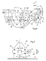
- the figure 6 presents a diagram showing the pivoting and tilting means.
- the rear power transmission box comprising a fixed portion 41 fixed to the cell 4 and a movable portion 42 carrying the rear rotor 10, the pivoting means 43 is for example a motor rotating the movable portion 42 relative to the portion fixed 41 around a tilting axis AX2.
- This figure 6 also shows means for controlling the pitch of the second blades 12 of the rear rotor 10.
- the tilt means 50 can act on the main power gearbox 30 to tilt the mast 31, by tilting this main power gearbox 30 about a tilt axis AX1 on both sides. another of a neutral location according to the double arrow F4.
- the aircraft To drive the main gearbox 30 and the power rear gearbox 40, the aircraft comprises a power plant 20 provided with at least one motor 21 setting in motion a main kinematic chain C1 connected to the main box 30 and a rear kinematic chain C2 connected to the rear gearbox 40 power.
- Sharing means 70 may be arranged between each kinematic chain and the motor or motors of the power plant 20.
- each motor drives a distribution gear train 71 of the partition means 70, the distribution pinion 71 meshing with a front pinion 72 connected to the main kinematic chain C1 and a rear pinion 73 linked to the rear kinematic chain C2.
- the aircraft 1 may comprise a first detaching means 61 between the main gearbox 30 and the power plant 20, and a second detaching means 62 between the rear gearbox 40 of power and the driving installation 20.
- the uncoupling means may be of the freewheel or clutch type, for example.
- a free wheel can be arranged between each motor and the sharing means.
- a pilot uses flight controls 80 acting on the pitch of the first blades of the rotary wing 2, such as a collective lever and a cyclic control sleeve of the blades of the rotary wing.
- this pilot uses a first control means 301 rudder type for example to control the yaw movement, or a second control means 302 to control the thrust generated by the tail rotor during the second mode of operation and the third mode Operating.
- a switching means 300 automatic or maneuverable by the driver to switch from one operating mode to another.
- the pilot controls the collective pitch of the first blades of the rotary wing with the collective lever, and the cyclic pitch of the first blades of the rotary wing with the cyclic control stick.
- the inclination of the mast 31 can be managed by the switching means 300 or by a dedicated member, controllable by the pilot.
- the pilot controls the yaw movement of the aircraft with the first control means 301, this first control means 301 acting on a servocontrol 44 linked to the second blades of the rear rotor.
- the second control means 302 is then inactive.
- the switching means 300 directs the pivoting means to pivot the rear rotor 10. From an angular threshold, the switching means 300 connects the first control means 301. by pivoting and activates the second control means 302.
- the pilot controls the yawing movement via the pivoting motor 43. Moreover, this pilot modifies the collective pitch of the second blades 12 to manage the thrust of the tail rotor using second control means 302 acting on said servocontrol 44.
- the switching means 300 orders the inclination means 50 to incline the mast 31 towards the rear end 4 "of the aircraft, according to a predetermined angle that may be adjustable to the help of said dedicated organ.
- the tilt means 50 may include a jack tilting the main gearbox 30.
- This main gearbox 30 is then arranged on a nacelle 32 fixed to the cell 4, for example via bearings 33.
- the figure 9 has a compensating means 90 which makes it possible not to introduce movement of the lever of the servo valve during an inclination of the rotary wing 2 and its mast 31 especially if the pilot maintains his controls 80 in a fixed position not cyclic or collective pitch of the first blades.
- the compensation means 90 comprises a return lever 91 connected to the flight controls 80 by an input link 92. This input link 92 is then articulated to one end of the return lever 91 and to a kinematic chain controlled by said flight controls 80.
- this return lever 91 is connected to the lever of the distributor of a control servo of the pitch of the first blades of the rotary wing 2 by an output rod 93, and to the cell 4 by a connecting rod 94.
- the return lever 91 rotates relative to the cell and exerts a force on the blades via in particular the output rod 93.
- the compensation means comprises a compensation rod 95 articulated to the connecting rod and to the casing of the main transmission gearbox 30.
Landscapes
- Engineering & Computer Science (AREA)
- Mechanical Engineering (AREA)
- Aviation & Aerospace Engineering (AREA)
- Transmission Devices (AREA)
- Toys (AREA)
Applications Claiming Priority (1)
| Application Number | Priority Date | Filing Date | Title |
|---|---|---|---|
| FR1005016A FR2969577B1 (fr) | 2010-12-22 | 2010-12-22 | Aeronef muni d'un rotor arriere basculant, et procede associe |
Publications (2)
| Publication Number | Publication Date |
|---|---|
| EP2468627A1 true EP2468627A1 (de) | 2012-06-27 |
| EP2468627B1 EP2468627B1 (de) | 2016-03-02 |
Family
ID=44305052
Family Applications (1)
| Application Number | Title | Priority Date | Filing Date |
|---|---|---|---|
| EP11009514.8A Active EP2468627B1 (de) | 2010-12-22 | 2011-12-01 | Luftfahrzeug, das mit einem rückseitigen Kipprotor ausgestattet ist, und entsprechendes Verfahren |
Country Status (4)
| Country | Link |
|---|---|
| US (1) | US8763949B2 (de) |
| EP (1) | EP2468627B1 (de) |
| CN (1) | CN102530249B (de) |
| FR (1) | FR2969577B1 (de) |
Cited By (1)
| Publication number | Priority date | Publication date | Assignee | Title |
|---|---|---|---|---|
| WO2019175266A1 (fr) * | 2018-03-13 | 2019-09-19 | Innostar | Aerodyne hybride de type vtol ou stol |
Families Citing this family (25)
| Publication number | Priority date | Publication date | Assignee | Title |
|---|---|---|---|---|
| US8600179B2 (en) * | 2009-09-17 | 2013-12-03 | Samsung Electronics Co., Ltd. | Method and apparatus for encoding and decoding image based on skip mode |
| WO2013105926A1 (en) | 2011-03-22 | 2013-07-18 | Aerovironment Inc. | Invertible aircraft |
| FR2977948B1 (fr) * | 2011-07-12 | 2014-11-07 | Eurocopter France | Procede de pilotage automatique d'un aeronef a voilure tournante comprenant au moins une helice propulsive, dispositif de pilotage automatique et aeronef |
| US9505492B2 (en) | 2012-02-23 | 2016-11-29 | Sikorsky Aircraft Corporation | Mission adaptive rotor blade |
| US9120567B2 (en) * | 2012-06-11 | 2015-09-01 | Sikorsky Aircraft Corporation | High speed compound rotary wing aircraft |
| CN103057702B (zh) * | 2012-12-25 | 2016-05-18 | 天津全华时代航天科技发展有限公司 | 喷气式旋翼直升机 |
| US9174730B2 (en) | 2013-08-21 | 2015-11-03 | Sikorsky Aircraft Corporation | Automated rotating tail rotor control |
| FR3014838B1 (fr) * | 2013-12-17 | 2015-12-25 | Eurocopter France | Giravion equipe d'un rotor arriere anti couple participant selectivement a la sustentation et a la propulsion en translation du giravion |
| FR3014837B1 (fr) * | 2013-12-17 | 2017-05-26 | Eurocopter France | Giravion equipe d'un rotor arriere anticouple participant a la sustentation du giravion par variation cyclique du pas des pales dudit rotor arriere |
| EP2899118B1 (de) * | 2014-01-27 | 2019-01-16 | AIRBUS HELICOPTERS DEUTSCHLAND GmbH | Hubschrauber mit einem Rumpf und mindestens einem Hauptrotor |
| US20170267338A1 (en) | 2014-10-01 | 2017-09-21 | Sikorsky Aircraft Corporation | Acoustic signature variation of aircraft utilizing a clutch |
| EP3201077B1 (de) | 2014-10-01 | 2020-05-20 | Sikorsky Aircraft Corporation | Doppelrotor, drehflügelflugzeug |
| US10112697B2 (en) * | 2015-05-11 | 2018-10-30 | Sikorsky Aircraft Corporation | Aircraft with thrust vectoring tail |
| US10167078B2 (en) * | 2015-09-21 | 2019-01-01 | Sikorsky Aircraft Corporation | Rotary or fixed wing aircraft with thrust vectoring tail |
| US10703471B2 (en) | 2016-06-03 | 2020-07-07 | Bell Helicopter Textron Inc. | Anti-torque control using matrix of fixed blade pitch motor modules |
| US10377479B2 (en) * | 2016-06-03 | 2019-08-13 | Bell Helicopter Textron Inc. | Variable directional thrust for helicopter tail anti-torque system |
| US10526085B2 (en) | 2016-06-03 | 2020-01-07 | Bell Textron Inc. | Electric distributed propulsion anti-torque redundant power and control system |
| CH713177A1 (de) * | 2016-11-21 | 2018-05-31 | Marenco Swisshelicopter Ag | Rotormast. |
| US11186185B2 (en) | 2017-05-31 | 2021-11-30 | Textron Innovations Inc. | Rotor brake effect by using electric distributed anti-torque generators and opposing electric motor thrust to slow a main rotor |
| US10831193B2 (en) * | 2017-11-14 | 2020-11-10 | Sikorsky Aircraft Corporation | Enhanced taxi control for rigid rotors |
| US11203424B2 (en) * | 2019-03-13 | 2021-12-21 | The Boeing Company | Slewing mechanical power transmissions for rotorcraft |
| CN109911218B (zh) * | 2019-03-13 | 2022-04-01 | 南京灵龙旋翼无人机系统研究院有限公司 | 一种用于旋转机翼飞机的多输入多输出动力系统及控制方法 |
| US11279477B2 (en) * | 2019-03-19 | 2022-03-22 | Textron Innovations Inc. | Rotating electric distributed anti-torque fin |
| US11230373B2 (en) * | 2019-12-02 | 2022-01-25 | Textron Innovations Inc. | Assembly and method for helicopter anti-torque |
| US11554860B1 (en) * | 2020-06-23 | 2023-01-17 | Piasecki Aircraft Corporation | Apparatus, system and method for a convertible thruster for a compound aircraft |
Citations (12)
| Publication number | Priority date | Publication date | Assignee | Title |
|---|---|---|---|---|
| GB599990A (en) | 1945-09-27 | 1948-03-25 | Cierva Autogiro Co Ltd | Improvements in helicopters |
| FR1017976A (fr) | 1947-07-27 | 1952-12-24 | Cierva Autogiro Co Ltd | Perfectionnement aux hélicoptères |
| US3155341A (en) | 1963-04-05 | 1964-11-03 | Ryan Aeronautical Co | Convertiplane |
| FR1511006A (fr) | 1966-12-13 | 1968-01-26 | Sud Aviation | Dispositif directionnel et propulsif pour hélicoptère |
| FR1536412A (fr) | 1967-07-06 | 1968-08-16 | United Aircraft Corp | Mécanisme de commande de pivotement du rotor de queue d'un convertiplane |
| FR2831934A1 (fr) | 2001-11-06 | 2003-05-09 | Eurocopter France | Boite de transmission basculante avec dispositif de rattrapage de jeu selon l'axe de basculement |
| FR2831933A1 (fr) | 2001-11-06 | 2003-05-09 | Eurocopter France | Boite de transmission basculante a liaison pivotante a paliers lisses |
| FR2831938A1 (fr) | 2001-11-07 | 2003-05-09 | Eurocopter France | Installation de lubrification pour boite de transmission de puissance basculante |
| FR2842271A1 (fr) | 2002-07-15 | 2004-01-16 | Eurocopter France | Boite de transmissiion de puissance basculante a transfert de charge par le carter |
| US20040232280A1 (en) | 2003-02-19 | 2004-11-25 | Carter Jay W. | Tilting mast in a rotorcraft |
| US20050045762A1 (en) | 2003-01-09 | 2005-03-03 | Pham Roger N. | High performance VTOL convertiplanes |
| WO2009102739A2 (en) | 2008-02-13 | 2009-08-20 | Bell Helicopter Textron Inc. | Rotorcraft with variable incident wing |
Family Cites Families (10)
| Publication number | Priority date | Publication date | Assignee | Title |
|---|---|---|---|---|
| BE466905A (de) * | ||||
| US2959373A (en) * | 1954-12-10 | 1960-11-08 | Daniel R Zuck | Convertiplane |
| US3004736A (en) * | 1959-10-06 | 1961-10-17 | Lockheed Aircraft Corp | Tail rotor for helicopter |
| US3540680A (en) * | 1968-05-24 | 1970-11-17 | Lockheed Aircraft Corp | Dual rotor system for helicopters |
| US3977812A (en) * | 1975-11-17 | 1976-08-31 | The United States Of America As Represented By The Secretary Of The Army | Compound helicopter drive means |
| US4759514A (en) * | 1986-09-30 | 1988-07-26 | The Boeing Company | Tail rotor yaw position control for a helicopter |
| US4912999A (en) * | 1987-09-30 | 1990-04-03 | The Boeing Company | System for pivotably supporting and transmitting power through a helicopter transmission and rotor |
| US5269654A (en) * | 1992-07-24 | 1993-12-14 | Don Chapman | Tail rotor assembly for helicopters |
| US5749540A (en) * | 1996-07-26 | 1998-05-12 | Arlton; Paul E. | System for controlling and automatically stabilizing the rotational motion of a rotary wing aircraft |
| US8210468B2 (en) * | 2007-05-14 | 2012-07-03 | Blr Aerospace, L.L.C. | Aircraft stabilizer system and methods of using the same |
-
2010
- 2010-12-22 FR FR1005016A patent/FR2969577B1/fr not_active Expired - Fee Related
-
2011
- 2011-12-01 EP EP11009514.8A patent/EP2468627B1/de active Active
- 2011-12-08 US US13/314,269 patent/US8763949B2/en active Active
- 2011-12-21 CN CN201110452859.2A patent/CN102530249B/zh not_active Expired - Fee Related
Patent Citations (12)
| Publication number | Priority date | Publication date | Assignee | Title |
|---|---|---|---|---|
| GB599990A (en) | 1945-09-27 | 1948-03-25 | Cierva Autogiro Co Ltd | Improvements in helicopters |
| FR1017976A (fr) | 1947-07-27 | 1952-12-24 | Cierva Autogiro Co Ltd | Perfectionnement aux hélicoptères |
| US3155341A (en) | 1963-04-05 | 1964-11-03 | Ryan Aeronautical Co | Convertiplane |
| FR1511006A (fr) | 1966-12-13 | 1968-01-26 | Sud Aviation | Dispositif directionnel et propulsif pour hélicoptère |
| FR1536412A (fr) | 1967-07-06 | 1968-08-16 | United Aircraft Corp | Mécanisme de commande de pivotement du rotor de queue d'un convertiplane |
| FR2831934A1 (fr) | 2001-11-06 | 2003-05-09 | Eurocopter France | Boite de transmission basculante avec dispositif de rattrapage de jeu selon l'axe de basculement |
| FR2831933A1 (fr) | 2001-11-06 | 2003-05-09 | Eurocopter France | Boite de transmission basculante a liaison pivotante a paliers lisses |
| FR2831938A1 (fr) | 2001-11-07 | 2003-05-09 | Eurocopter France | Installation de lubrification pour boite de transmission de puissance basculante |
| FR2842271A1 (fr) | 2002-07-15 | 2004-01-16 | Eurocopter France | Boite de transmissiion de puissance basculante a transfert de charge par le carter |
| US20050045762A1 (en) | 2003-01-09 | 2005-03-03 | Pham Roger N. | High performance VTOL convertiplanes |
| US20040232280A1 (en) | 2003-02-19 | 2004-11-25 | Carter Jay W. | Tilting mast in a rotorcraft |
| WO2009102739A2 (en) | 2008-02-13 | 2009-08-20 | Bell Helicopter Textron Inc. | Rotorcraft with variable incident wing |
Cited By (4)
| Publication number | Priority date | Publication date | Assignee | Title |
|---|---|---|---|---|
| WO2019175266A1 (fr) * | 2018-03-13 | 2019-09-19 | Innostar | Aerodyne hybride de type vtol ou stol |
| WO2019175264A1 (fr) * | 2018-03-13 | 2019-09-19 | Innostar | Procedure de manœuvre d'un aerodyne hybride de type vtol ou stol |
| FR3078945A1 (fr) * | 2018-03-13 | 2019-09-20 | Innostar | Aerodyne hybride de type vtol ou stol (basculement rotor) |
| US11639217B2 (en) | 2018-03-13 | 2023-05-02 | Innostar | Procedure for maneuvering a hybrid aerodyne of VTOL or STOL |
Also Published As
| Publication number | Publication date |
|---|---|
| CN102530249A (zh) | 2012-07-04 |
| CN102530249B (zh) | 2015-05-06 |
| US20120160954A1 (en) | 2012-06-28 |
| FR2969577A1 (fr) | 2012-06-29 |
| EP2468627B1 (de) | 2016-03-02 |
| FR2969577B1 (fr) | 2012-12-21 |
| US8763949B2 (en) | 2014-07-01 |
Similar Documents
| Publication | Publication Date | Title |
|---|---|---|
| EP2468627B1 (de) | Luftfahrzeug, das mit einem rückseitigen Kipprotor ausgestattet ist, und entsprechendes Verfahren | |
| EP2407377B1 (de) | Verfahren und Luftfahrzeug, das mit einem Heck-Kipprotor ausgestattet ist | |
| EP3294624B1 (de) | Konvertierbares flugzeug mit exponierbaren rotoren | |
| EP2146896B1 (de) | Schneller weitbereichs-hybridhelikopter | |
| EP2146895B1 (de) | Schneller weitbereichs-hybridhelikopter und optimierter heberotor | |
| EP2148814B1 (de) | Schneller weitbereichs-hybridhelikopter mit längshaltungssteuerung | |
| EP2886459B1 (de) | Drehflügelflugzeug, das mit einer Heckrotorkonfiguration ausgestattet ist, die selektiv an der Auftriebs- und Translationsbewegung des Drehflügelflugzeugs beteiligt ist | |
| EP1212238B1 (de) | Verbessertes schwenkrotor-verwandlungsflugzeug | |
| EP2574546B1 (de) | Hybrid rotary wing aircraft | |
| EP2233396B1 (de) | Verfahren und Vorrichtung zur Leistungsoptimierung von Propellern, die an beiden Seiten vom Rumpf eines Drehflüglers angeordnet sind | |
| EP3560830B1 (de) | Drehflügelflugzeug, das mit drehflügeln und mindestens zwei propellern ausgestattet ist, und von diesem drehflügelflugzeug angewandtes verfahren | |
| FR2983171A1 (fr) | Dispositif anti-couple a poussee longitudinale pour un giravion | |
| WO2008142258A2 (fr) | Système de commande d'un giravion | |
| EP2567893A1 (de) | Schnelles Luftfahrzeug für lange Strecken | |
| EP3882129B1 (de) | Verfahren zur steuerung der propeller eines hybridhubschraubers und hybridhubschrauber | |
| FR3036379A1 (fr) | Drone avec rotor a pas variable | |
| EP3212498A1 (de) | Verbesserungen an drehmaschinen mit einem fluidrotor mit verstellbaren schaufeln | |
| FR3071223A1 (fr) | Helicoptere hybride comportant des helices de propulsion inclinees | |
| WO2022171958A1 (fr) | Aeronef vtol a quatre rotors en croix et procede de gestion d'atterrissage d'urgence associe | |
| FR3103463A1 (fr) | Procédé de gestion d’atterrissage d’urgence dans un aéronef VTOL à quatre rotors opposés deux à deux et aéronef VTOL associé | |
| FR3123320A1 (fr) | Aéronef ayant au moins une hélice et une voilure tournante munie de deux rotors portés par deux demi ailes | |
| FR3119837A1 (fr) | Aéronef VTOL à quatre rotors et procédé de gestion d’atterrissage d’urgence associé | |
| BE464896A (de) |
Legal Events
| Date | Code | Title | Description |
|---|---|---|---|
| AK | Designated contracting states |
Kind code of ref document: A1 Designated state(s): AL AT BE BG CH CY CZ DE DK EE ES FI FR GB GR HR HU IE IS IT LI LT LU LV MC MK MT NL NO PL PT RO RS SE SI SK SM TR |
|
| AX | Request for extension of the european patent |
Extension state: BA ME |
|
| PUAI | Public reference made under article 153(3) epc to a published international application that has entered the european phase |
Free format text: ORIGINAL CODE: 0009012 |
|
| 17P | Request for examination filed |
Effective date: 20120605 |
|
| 17Q | First examination report despatched |
Effective date: 20131025 |
|
| RAP1 | Party data changed (applicant data changed or rights of an application transferred) |
Owner name: AIRBUS HELICOPTERS |
|
| GRAP | Despatch of communication of intention to grant a patent |
Free format text: ORIGINAL CODE: EPIDOSNIGR1 |
|
| INTG | Intention to grant announced |
Effective date: 20151002 |
|
| GRAS | Grant fee paid |
Free format text: ORIGINAL CODE: EPIDOSNIGR3 |
|
| GRAA | (expected) grant |
Free format text: ORIGINAL CODE: 0009210 |
|
| AK | Designated contracting states |
Kind code of ref document: B1 Designated state(s): AL AT BE BG CH CY CZ DE DK EE ES FI FR GB GR HR HU IE IS IT LI LT LU LV MC MK MT NL NO PL PT RO RS SE SI SK SM TR |
|
| REG | Reference to a national code |
Ref country code: GB Ref legal event code: FG4D Free format text: NOT ENGLISH |
|
| REG | Reference to a national code |
Ref country code: AT Ref legal event code: REF Ref document number: 777823 Country of ref document: AT Kind code of ref document: T Effective date: 20160315 Ref country code: CH Ref legal event code: EP |
|
| REG | Reference to a national code |
Ref country code: IE Ref legal event code: FG4D Free format text: LANGUAGE OF EP DOCUMENT: FRENCH |
|
| REG | Reference to a national code |
Ref country code: DE Ref legal event code: R096 Ref document number: 602011023540 Country of ref document: DE |
|
| REG | Reference to a national code |
Ref country code: NL Ref legal event code: MP Effective date: 20160302 |
|
| REG | Reference to a national code |
Ref country code: LT Ref legal event code: MG4D |
|
| REG | Reference to a national code |
Ref country code: AT Ref legal event code: MK05 Ref document number: 777823 Country of ref document: AT Kind code of ref document: T Effective date: 20160302 |
|
| PG25 | Lapsed in a contracting state [announced via postgrant information from national office to epo] |
Ref country code: NO Free format text: LAPSE BECAUSE OF FAILURE TO SUBMIT A TRANSLATION OF THE DESCRIPTION OR TO PAY THE FEE WITHIN THE PRESCRIBED TIME-LIMIT Effective date: 20160602 Ref country code: HR Free format text: LAPSE BECAUSE OF FAILURE TO SUBMIT A TRANSLATION OF THE DESCRIPTION OR TO PAY THE FEE WITHIN THE PRESCRIBED TIME-LIMIT Effective date: 20160302 Ref country code: FI Free format text: LAPSE BECAUSE OF FAILURE TO SUBMIT A TRANSLATION OF THE DESCRIPTION OR TO PAY THE FEE WITHIN THE PRESCRIBED TIME-LIMIT Effective date: 20160302 Ref country code: GR Free format text: LAPSE BECAUSE OF FAILURE TO SUBMIT A TRANSLATION OF THE DESCRIPTION OR TO PAY THE FEE WITHIN THE PRESCRIBED TIME-LIMIT Effective date: 20160603 Ref country code: ES Free format text: LAPSE BECAUSE OF FAILURE TO SUBMIT A TRANSLATION OF THE DESCRIPTION OR TO PAY THE FEE WITHIN THE PRESCRIBED TIME-LIMIT Effective date: 20160302 |
|
| PG25 | Lapsed in a contracting state [announced via postgrant information from national office to epo] |
Ref country code: SE Free format text: LAPSE BECAUSE OF FAILURE TO SUBMIT A TRANSLATION OF THE DESCRIPTION OR TO PAY THE FEE WITHIN THE PRESCRIBED TIME-LIMIT Effective date: 20160302 Ref country code: RS Free format text: LAPSE BECAUSE OF FAILURE TO SUBMIT A TRANSLATION OF THE DESCRIPTION OR TO PAY THE FEE WITHIN THE PRESCRIBED TIME-LIMIT Effective date: 20160302 Ref country code: AT Free format text: LAPSE BECAUSE OF FAILURE TO SUBMIT A TRANSLATION OF THE DESCRIPTION OR TO PAY THE FEE WITHIN THE PRESCRIBED TIME-LIMIT Effective date: 20160302 Ref country code: NL Free format text: LAPSE BECAUSE OF FAILURE TO SUBMIT A TRANSLATION OF THE DESCRIPTION OR TO PAY THE FEE WITHIN THE PRESCRIBED TIME-LIMIT Effective date: 20160302 Ref country code: LV Free format text: LAPSE BECAUSE OF FAILURE TO SUBMIT A TRANSLATION OF THE DESCRIPTION OR TO PAY THE FEE WITHIN THE PRESCRIBED TIME-LIMIT Effective date: 20160302 Ref country code: LT Free format text: LAPSE BECAUSE OF FAILURE TO SUBMIT A TRANSLATION OF THE DESCRIPTION OR TO PAY THE FEE WITHIN THE PRESCRIBED TIME-LIMIT Effective date: 20160302 Ref country code: PL Free format text: LAPSE BECAUSE OF FAILURE TO SUBMIT A TRANSLATION OF THE DESCRIPTION OR TO PAY THE FEE WITHIN THE PRESCRIBED TIME-LIMIT Effective date: 20160302 |
|
| PG25 | Lapsed in a contracting state [announced via postgrant information from national office to epo] |
Ref country code: IS Free format text: LAPSE BECAUSE OF FAILURE TO SUBMIT A TRANSLATION OF THE DESCRIPTION OR TO PAY THE FEE WITHIN THE PRESCRIBED TIME-LIMIT Effective date: 20160702 Ref country code: EE Free format text: LAPSE BECAUSE OF FAILURE TO SUBMIT A TRANSLATION OF THE DESCRIPTION OR TO PAY THE FEE WITHIN THE PRESCRIBED TIME-LIMIT Effective date: 20160302 |
|
| PG25 | Lapsed in a contracting state [announced via postgrant information from national office to epo] |
Ref country code: SK Free format text: LAPSE BECAUSE OF FAILURE TO SUBMIT A TRANSLATION OF THE DESCRIPTION OR TO PAY THE FEE WITHIN THE PRESCRIBED TIME-LIMIT Effective date: 20160302 Ref country code: RO Free format text: LAPSE BECAUSE OF FAILURE TO SUBMIT A TRANSLATION OF THE DESCRIPTION OR TO PAY THE FEE WITHIN THE PRESCRIBED TIME-LIMIT Effective date: 20160302 Ref country code: PT Free format text: LAPSE BECAUSE OF FAILURE TO SUBMIT A TRANSLATION OF THE DESCRIPTION OR TO PAY THE FEE WITHIN THE PRESCRIBED TIME-LIMIT Effective date: 20160704 Ref country code: SM Free format text: LAPSE BECAUSE OF FAILURE TO SUBMIT A TRANSLATION OF THE DESCRIPTION OR TO PAY THE FEE WITHIN THE PRESCRIBED TIME-LIMIT Effective date: 20160302 Ref country code: CZ Free format text: LAPSE BECAUSE OF FAILURE TO SUBMIT A TRANSLATION OF THE DESCRIPTION OR TO PAY THE FEE WITHIN THE PRESCRIBED TIME-LIMIT Effective date: 20160302 |
|
| REG | Reference to a national code |
Ref country code: DE Ref legal event code: R097 Ref document number: 602011023540 Country of ref document: DE |
|
| REG | Reference to a national code |
Ref country code: FR Ref legal event code: PLFP Year of fee payment: 6 |
|
| PLBE | No opposition filed within time limit |
Free format text: ORIGINAL CODE: 0009261 |
|
| STAA | Information on the status of an ep patent application or granted ep patent |
Free format text: STATUS: NO OPPOSITION FILED WITHIN TIME LIMIT |
|
| PG25 | Lapsed in a contracting state [announced via postgrant information from national office to epo] |
Ref country code: DK Free format text: LAPSE BECAUSE OF FAILURE TO SUBMIT A TRANSLATION OF THE DESCRIPTION OR TO PAY THE FEE WITHIN THE PRESCRIBED TIME-LIMIT Effective date: 20160302 |
|
| 26N | No opposition filed |
Effective date: 20161205 |
|
| PG25 | Lapsed in a contracting state [announced via postgrant information from national office to epo] |
Ref country code: BG Free format text: LAPSE BECAUSE OF FAILURE TO SUBMIT A TRANSLATION OF THE DESCRIPTION OR TO PAY THE FEE WITHIN THE PRESCRIBED TIME-LIMIT Effective date: 20160602 Ref country code: SI Free format text: LAPSE BECAUSE OF FAILURE TO SUBMIT A TRANSLATION OF THE DESCRIPTION OR TO PAY THE FEE WITHIN THE PRESCRIBED TIME-LIMIT Effective date: 20160302 |
|
| PG25 | Lapsed in a contracting state [announced via postgrant information from national office to epo] |
Ref country code: BE Free format text: LAPSE BECAUSE OF NON-PAYMENT OF DUE FEES Effective date: 20161231 |
|
| REG | Reference to a national code |
Ref country code: DE Ref legal event code: R119 Ref document number: 602011023540 Country of ref document: DE |
|
| REG | Reference to a national code |
Ref country code: CH Ref legal event code: PL |
|
| PG25 | Lapsed in a contracting state [announced via postgrant information from national office to epo] |
Ref country code: MC Free format text: LAPSE BECAUSE OF FAILURE TO SUBMIT A TRANSLATION OF THE DESCRIPTION OR TO PAY THE FEE WITHIN THE PRESCRIBED TIME-LIMIT Effective date: 20160302 |
|
| REG | Reference to a national code |
Ref country code: IE Ref legal event code: MM4A |
|
| PG25 | Lapsed in a contracting state [announced via postgrant information from national office to epo] |
Ref country code: LI Free format text: LAPSE BECAUSE OF NON-PAYMENT OF DUE FEES Effective date: 20161231 Ref country code: CH Free format text: LAPSE BECAUSE OF NON-PAYMENT OF DUE FEES Effective date: 20161231 Ref country code: LU Free format text: LAPSE BECAUSE OF NON-PAYMENT OF DUE FEES Effective date: 20161201 |
|
| PG25 | Lapsed in a contracting state [announced via postgrant information from national office to epo] |
Ref country code: DE Free format text: LAPSE BECAUSE OF NON-PAYMENT OF DUE FEES Effective date: 20170701 Ref country code: IE Free format text: LAPSE BECAUSE OF NON-PAYMENT OF DUE FEES Effective date: 20161201 |
|
| REG | Reference to a national code |
Ref country code: FR Ref legal event code: PLFP Year of fee payment: 7 |
|
| REG | Reference to a national code |
Ref country code: BE Ref legal event code: MM Effective date: 20161231 |
|
| PG25 | Lapsed in a contracting state [announced via postgrant information from national office to epo] |
Ref country code: CY Free format text: LAPSE BECAUSE OF FAILURE TO SUBMIT A TRANSLATION OF THE DESCRIPTION OR TO PAY THE FEE WITHIN THE PRESCRIBED TIME-LIMIT Effective date: 20160302 Ref country code: HU Free format text: LAPSE BECAUSE OF FAILURE TO SUBMIT A TRANSLATION OF THE DESCRIPTION OR TO PAY THE FEE WITHIN THE PRESCRIBED TIME-LIMIT; INVALID AB INITIO Effective date: 20111201 |
|
| PG25 | Lapsed in a contracting state [announced via postgrant information from national office to epo] |
Ref country code: MK Free format text: LAPSE BECAUSE OF FAILURE TO SUBMIT A TRANSLATION OF THE DESCRIPTION OR TO PAY THE FEE WITHIN THE PRESCRIBED TIME-LIMIT Effective date: 20160302 Ref country code: TR Free format text: LAPSE BECAUSE OF FAILURE TO SUBMIT A TRANSLATION OF THE DESCRIPTION OR TO PAY THE FEE WITHIN THE PRESCRIBED TIME-LIMIT Effective date: 20160302 |
|
| PG25 | Lapsed in a contracting state [announced via postgrant information from national office to epo] |
Ref country code: MT Free format text: LAPSE BECAUSE OF FAILURE TO SUBMIT A TRANSLATION OF THE DESCRIPTION OR TO PAY THE FEE WITHIN THE PRESCRIBED TIME-LIMIT Effective date: 20160302 |
|
| PG25 | Lapsed in a contracting state [announced via postgrant information from national office to epo] |
Ref country code: AL Free format text: LAPSE BECAUSE OF FAILURE TO SUBMIT A TRANSLATION OF THE DESCRIPTION OR TO PAY THE FEE WITHIN THE PRESCRIBED TIME-LIMIT Effective date: 20160302 |
|
| PGFP | Annual fee paid to national office [announced via postgrant information from national office to epo] |
Ref country code: GB Payment date: 20221223 Year of fee payment: 12 |
|
| P01 | Opt-out of the competence of the unified patent court (upc) registered |
Effective date: 20230530 |
|
| GBPC | Gb: european patent ceased through non-payment of renewal fee |
Effective date: 20231201 |
|
| PG25 | Lapsed in a contracting state [announced via postgrant information from national office to epo] |
Ref country code: GB Free format text: LAPSE BECAUSE OF NON-PAYMENT OF DUE FEES Effective date: 20231201 |
|
| PG25 | Lapsed in a contracting state [announced via postgrant information from national office to epo] |
Ref country code: GB Free format text: LAPSE BECAUSE OF NON-PAYMENT OF DUE FEES Effective date: 20231201 |
|
| PGFP | Annual fee paid to national office [announced via postgrant information from national office to epo] |
Ref country code: IT Payment date: 20251223 Year of fee payment: 15 |
|
| PGFP | Annual fee paid to national office [announced via postgrant information from national office to epo] |
Ref country code: FR Payment date: 20251222 Year of fee payment: 15 |