EP2468638A1 - Machine d'emballage et procédé de production d'un emballage sous vide - Google Patents
Machine d'emballage et procédé de production d'un emballage sous vide Download PDFInfo
- Publication number
- EP2468638A1 EP2468638A1 EP11007717A EP11007717A EP2468638A1 EP 2468638 A1 EP2468638 A1 EP 2468638A1 EP 11007717 A EP11007717 A EP 11007717A EP 11007717 A EP11007717 A EP 11007717A EP 2468638 A1 EP2468638 A1 EP 2468638A1
- Authority
- EP
- European Patent Office
- Prior art keywords
- chamber
- pressure
- chambers
- packaging machine
- supply air
- Prior art date
- Legal status (The legal status is an assumption and is not a legal conclusion. Google has not performed a legal analysis and makes no representation as to the accuracy of the status listed.)
- Granted
Links
Images




Classifications
-
- B—PERFORMING OPERATIONS; TRANSPORTING
- B65—CONVEYING; PACKING; STORING; HANDLING THIN OR FILAMENTARY MATERIAL
- B65B—MACHINES, APPARATUS OR DEVICES FOR, OR METHODS OF, PACKAGING ARTICLES OR MATERIALS; UNPACKING
- B65B31/00—Packaging articles or materials under special atmospheric or gaseous conditions; Adding propellants to aerosol containers
- B65B31/02—Filling, closing, or filling and closing, containers or wrappers in chambers maintained under vacuum or superatmospheric pressure or containing a special atmosphere, e.g. of inert gas
- B65B31/024—Filling, closing, or filling and closing, containers or wrappers in chambers maintained under vacuum or superatmospheric pressure or containing a special atmosphere, e.g. of inert gas specially adapted for wrappers or bags
Definitions
- the invention relates to a packaging machine according to the preamble of claim 1, and to a corresponding method for producing a vacuum packaging.
- a generic packaging machine and a method for producing a vacuum packaging go out of the EP 1564147 A1 out.
- a sealable vacuum bag is placed in the packaging machine such that a main portion of the package receiving the packaged product is in the first chamber while the opening of the bag is in a smaller, second chamber.
- the advantage of this packaging machine is that in the two chambers, a different negative pressure can be generated so that from the outside a higher pressure on the packaging loads than inside. This higher external pressure stabilizes delicate products in the package, such as cheese or other porous products, which tend to be too low pressure to spew or burst the porous structures and thus damage the product.
- a disadvantage of the conventional packaging machine is that its operation is relatively expensive.
- a seal chamber is divided by the package into a sub-chamber and an upper chamber.
- a quick, sudden venting of the chamber provides a pressure difference between the interior and the exterior of the package, after initially creating a predetermined vacuum.
- the object of the present invention is to improve a packaging machine and a packaging method for producing a vacuum packaging with a view to more stable operation and higher-quality packaging results.
- a first variant of the invention provides that the supply air valve is a control valve which depends on the difference in the measured by the two pressure measuring means pressure in the first and the second chamber and / or in dependence on the difference between the prevailing in a chamber Pressure and a predetermined final pressure for this chamber is adjustable.
- control valve means in the context of the invention that the valve can not only assume a fully open and a fully closed state, but also a plurality of intermediate positions in which the control valve is partially open. These intermediate steps may be distributed in discrete opening steps or continuously between the fully opened and the fully closed positions. It would also be conceivable that the control valve is infinitely adjustable only in a certain range. It thus differs markedly from the above cited prior art, in which switching valves were used, which could be adjusted only between a fully open and a fully closed state.
- Another advantage of the invention arises from the fact that the difference between the pressure measured by means of the two pressure measuring devices in the two chambers is determined and used as input for the regulation of the supply air valve.
- the per unit of time in the first chamber supplied amount of air thus depends on this pressure difference.
- the pressure difference is small, more air per unit time is supplied to the first chamber.
- the pressure difference is larger, no or at least less air per unit time is supplied to the first chamber so as not to make the pressure difference between the two chambers too large. In this way, it is ensured that on the outside of the packaging in the first chamber, there is always an ideal pressure, so that damage to the products by bursting or beading of porous structures is reliably avoided.
- By maintaining an optimum pressure difference constantly moreover, the processing time when producing a vacuum packaging can be shortened.
- the supply air valve is a proportional valve whose degree of opening is inversely proportional to the difference of the pressure in the two chambers.
- a proportional valve allows a continuous adjustment of its degree of opening between the fully closed and the fully open position.
- the supply air valve can have either a linear or a non-linear control curve.
- a non-linear control curve which has a non-linear profile relative to the pressure difference between the two chambers, is particularly advantageous.
- This control curve could, for example, be S-shaped in order to allow as gentle a pressure regulation as possible.
- a desired final pressure for one or both chambers and / or a desired pressure difference between the pressures prevailing in the two chambers is set on the packaging machine.
- the supply air valve can then be controlled via a suitable control so that this target pressure difference is maintained as constant as possible. It is even better if the desired pressure difference is adjustable, for example via suitable control elements on the packaging machine.
- the target pressure difference can be adapted to different products or to different materials of the packaging in order to always produce optimum packaging results.
- the desired pressure difference need not be a single, concrete value, but the desired pressure difference may preferably be a pressure range. For example, if the desired pressure difference between the two chambers is 100 mbar, the target pressure difference may be a pressure range between 90 mbar and 110 mbar.
- the degree of opening of the supply air valve is inversely proportional to the amount by which the actual pressure difference between the pressures prevailing in the two chambers deviates from the desired pressure difference.
- the supply air valve has a first opening degree.
- the supply air valve continues to open in proportion to the amount by which the actual pressure difference exceeds the target pressure difference. In this way, the fastest possible return of the actual pressure difference to the range of the desired pressure difference is made possible.
- a dividing wall is provided between the two evacuable chambers. This partition has the advantage that different pressures can prevail in the two chambers.
- an opening of the supply air valve is arranged to the first chamber in one of the partition wall exactly opposite wall of the first chamber.
- This arrangement ensures that the supplied air initially acts on the end of the packaging remote from the dividing wall before the air sweeps along the packaging and flows to the dividing wall.
- This has the advantage that residual air still contained in the packaging is pressed to open the packaging, so that the evacuation of the packaging is facilitated and accelerated.
- the partition there may be a gap through which the first chamber and the second chamber are in fluid communication with each other.
- a part of the packaging may be inserted into this gap in order to store and stabilize the packaging relative to the packaging machine.
- the gap also allows a small exchange of air between the two chambers. This has the advantage that an air flow can be generated along the packaging, which is directed along the packaging to the opening. This facilitates the evacuation of the packaging.
- the fluid connection between the two chambers allows a variant in which not each chamber is evacuated separately, but in which only in a chamber-preferably in the opening of the packaging receiving, the second chamber - an evacuation is provided. When evacuating the second chamber, the first chamber is automatically evacuated by means of the gap.
- the opening of the supply air valve to the first chamber is preferably arranged in the height of this gap. This further promotes the formation of an air flow along the package, which is directed from the end of the package to the packaging opening and presses the residual air still contained in the packaging to open the package.
- an adjuster for changing and adjusting the cross-sectional area of the gap is provided. This makes it possible to adjust the volume flow between the two chambers, d. H. the amount of air exchanged per unit time between the two chambers.
- such an adjuster for changing and adjusting the cross-sectional area of the gap in the partition wall between the two chambers and independently of the pressure measurement in the two chambers and the formation of a Supply air valves are provided as a control valve.
- the adjuster allows adjustment of the volume flow exchanged between the two chambers. Depending on the nature of the products to be packaged and the materials used for the packaging of this volume flow can now be changed to achieve the fastest possible or the highest possible evacuation of the packaging.
- the adjuster can also be manually operated or adjustable.
- the operation of the packaging machine is more comfortable when the adjuster is driven by a motor and the operator for this purpose, for example, by means of a control panel or control element gives appropriate setting commands.
- the set values can be stored in a control of the machine.
- the adjuster may have an adjusting screw which projects into the gap or which moves a blocking element projecting into the gap.
- the partition between the two chambers or at least a part of this partition is mounted such that the cross-sectional area of the gap does not change, even if one or both chambers are evacuated.
- the partition or at least a part thereof is resiliently mounted relative to the bottom, the lid or a wall of the chambers. This prevents, for example, a deflection of a lid of the packaging machine at a greatly reduced internal pressure to a displacement of the partition and thus leads to a change in the gap cross-sectional area, which could either prevent a pressure adjustment between the chambers or could lead to an immediate pressure equalization, both equally disadvantageous would be.
- noses or projections could also be provided on the gap, which strike against the opposite gap side and thus prevent the gap from closing below a certain minimum opening area.
- a significant improvement of the packaging machine can also be achieved by providing a bypass between the two chambers to be evacuated, in which a controllable bypass valve is arranged.
- a controllable bypass valve By the degree of opening of the bypass valve can be controlled how much air flows from one of the chambers into the other chamber, so as to set the differential pressure between the two chambers also independent or at least largely independent of the gap.
- the adjustable bypass valve It also makes it possible to adjust the pressure equalization between the two chambers to different numbers of bags or to different thick-walled bag without necessarily the gap would have to be changed. Alternatively, it would also be conceivable that no bypass between the two chambers is provided, but that is evacuated in the smaller chamber with full power and evacuated in the larger chamber with reduced power.
- the invention further relates to a method for producing a vacuum packaging, wherein in a first and in a second evacuated chamber, the pressure is measured, from which the actual pressure difference determined and a controllable supply air valve depending on this actual pressure difference between in the controlling both chambers prevailing pressures, or in dependence on the difference between the pressure prevailing in a chamber and a predetermined final pressure for this chamber.
- the supply air valve is opened in proportion to a pressure difference and / or if a desired pressure difference is predetermined by an operator.
- the supply air valve can then be opened proportionally (or inversely proportional) to the extent to which the pressure difference between the pressures prevailing in the two chambers deviates from the desired pressure difference.
- the desired pressure difference does not have to be a single, concrete value, but is preferably a finite pressure range.
- a bypass with a bypass valve between the two chambers is provided for carrying out the method according to the invention.
- the final pressure reached in the two chambers and the end vacuum reached there is determined by the position of the supply air valve and thus adjusted to a predetermined final vacuum, while the position of the controllable bypass valve prevailing between the two chambers differential pressure and, for example, to a predetermined differential pressure is equalized.
- FIG. 1 shows a schematic representation of an embodiment of a packaging machine according to the invention 1. It serves to make a package 2 to a product 3 by suitable evacuation and sealing to a vacuum packaging.
- the packaging 2 is preferably a bag made of a sealable plastic.
- the product 3 may be, for example, cheese or another product that has bubbles or porous structures that could damage the product 3 if the external vacuum is too high.
- the packaging machine 1 has a first evacuable chamber 4 and a second evacuatable chamber 5.
- the first chamber 4 is larger than the second chamber 5.
- the product 3 receiving section 2a of the package 2 can be accommodated.
- an opening portion 2b of the package 2 can be accommodated so that an opening 2c of the package 2 is exposed in the second chamber 5 freely.
- a common partition 6 is provided between the first chamber 4 and the second chamber 5.
- the package 2 extends through the gap 7 from the first chamber 4 into the second chamber 5.
- a sealing material 8 may be provided to at least partially seal the gap 7 against the package 2.
- a first evacuation valve 9 is provided, via which the first chamber 4 can be evacuated.
- a second evacuation valve 10 is provided, by means of which the second chamber 5 can be evacuated. Both evacuation valves 9, 10 are connected to a common vacuum pump (not shown) and can be independently opened or closed.
- a first pressure measuring device 11 is provided for measuring the pressure in the first chamber 4.
- a second pressure measuring device 12 is provided on or in the second chamber 5 and serves to measure the pressure in the second chamber 5.
- the packaging machine 1 also has an inlet air valve 13. It serves to be able to supply air into the first chamber 4 via an inlet air opening 14.
- In the supply air valve 13 is a control valve, which can preferably be adjusted continuously between a fully closed and a fully open position.
- a controller 15 of the packaging machine 1 is connected via control and data lines 16 to the valves 9, 10, 13 and the pressure measuring devices 11, 12.
- the measured values of the pressure in the two chambers 4, 5 determined by means of the pressure measuring devices 11, 12 are transmitted to the controller 15 via the data lines 16.
- the controller is configured to determine from the values obtained by the two pressure measuring devices 11, 12 the pressure difference between the pressures prevailing in the two chambers 4, 5. It is also configured to control the evacuation valves 9, 10 as a function of the pressure prevailing in the respective chamber 4, 5 and the supply air valve 13 as a function of the difference between the pressure prevailing in the two chambers 4, 5.
- An adjuster or actuator 17 is provided to change the cross-sectional area of the gap 7 and adjust.
- the adjuster 17 is designed as a set screw, which is guided in the partition wall 6.
- An electric motor 18 outside the two chambers 4, 5 has a drive nut 19, which surrounds the adjusting screw 17. When the nut 19 is driven by the motor 18, it raises or lowers the adjusting screw 17 so as to change the free cross-sectional area of the gap 7. Also, the motor 18 is connected via a suitable control line to the controller 15.
- the supply air opening 14, via which the supply air valve 13 supply air can be guided into the first chamber 4, is arranged in the partition wall 6 opposite wall 20 of the first chamber 4. In particular, it lies there at approximately the same height H with respect to the bottom 21 of the chamber 4 as the gap 7 in the partition wall 6.
- the packaging machine 1 further has a sealing tool with a sealing tool upper part 22 and a sealing tool lower part 23.
- the sealing tool is arranged in the second chamber 5 and it is also controlled by the controller 15.
- the sealing tool 22, 23 could also be arranged in the first chamber 4.
- the sealing tool parts 22, 23 can be moved toward each other to airtight seal the opening portion 2 b of the package 2 by applying pressure and a sealing temperature.
- the packaging machine 1 still has an operating device 24, which may be a group of operating elements such as buttons or the like, and / or a touch screen.
- an operator of the packaging machine can enter commands or set specific values, in particular a desired pressure difference for the pressure difference in the two chambers 4, 5 as well as the desired final pressure in one or both chambers.
- This desired pressure difference can either be a single, concrete value or else a pressure range lying between two values. In the latter case, the range can be set either by the operator setting the lower and upper limits of this target pressure difference range. Alternatively, the operator may set a certain value within the target pressure difference range, for example, a middle range.
- the packaging machine 1 itself or the operator set a tolerance range to this central value, for example, a percentage deviation of 5 or 10% up and down. If the actual pressure difference lies within this tolerance range around the predetermined pressure difference value, it is treated as lying within the desired pressure difference range.
- the operation of the packaging machine 1 according to the invention or the process according to the invention proceeds as follows.
- the operator inputs a desired pressure difference value or a desired pressure difference range as well as the desired final pressure in one or both chambers into the controller 15 into the packaging machine 1, for example 100 mbar, 150 mbar, 200 mbar or 250 mbar.
- a desired pressure difference value or a desired pressure difference range as well as the desired final pressure in one or both chambers into the controller 15 into the packaging machine 1, for example 100 mbar, 150 mbar, 200 mbar or 250 mbar.
- the motor 18 of the adjuster 17 it is possible by means of the motor 18 of the adjuster 17 to be moved in order to change the free cross-sectional area of the gap 7, if this does not yet have the desired value.
- the operator opens the two chambers 4, 5 of the packaging machine 1 and places a packaging 2 filled with a product 3 into the packaging machine 1. This insertion can be done manually or automatically. After insertion, the product receiving portion 2a of the package 2 is located in the first chamber 4, while the opening portion 2b of the package 2 is located in the second chamber 5. The chambers 4, 5 are closed.
- the controller 15 provides for opening the two evacuation valves 9, 10.
- the pressure in the two chambers 4, 5 drops. Since the volume of the second chamber 5 is smaller than that of the first chamber 4, the pressure in the second chamber 5 decreases faster than in the first chamber 4. Since the opening 2c of the package 2 is in communication with the second chamber 5, the lower pressure of the second chamber 5 also in the interior of the package 2. As a result, the product receiving portion 2a of the package 2 is used to the product 3.
- the pressure measuring devices 11, 12 monitor the pressure in the respective chambers 4, 5 continuously or at discrete intervals.
- the corresponding pressure measured values are transmitted to the central controller 15, which calculates the pressure difference between the two chambers 4, 5.
- This pressure difference increases until it reaches the tolerance range of the desired pressure difference. So that the pressure difference reaches this predetermined value faster, either the first evacuation valve 9 is opened after the second evacuation valve 10 or the supply air valve 13 is opened during the evacuation of the two chambers 4, 5.
- the higher external pressure in the first chamber 4 presses the product-receiving portion 2a of the package 2 to the product 3.
- Favored by the position of the supply air opening 14 in the wall 20 of the first chamber 4 forms a Air flow from this supply air opening 14 to the gap 7, preferably a laminar air flow. It sweeps along the product receiving portion 2a of the package 2, thus pushing the residual air contained in the package 2 toward the opening 2c of the package 2.
- the supply air valve 13 designed as a control valve is slowly closed. This closing of the supply air valve 13 may be proportional to the speed at which the pressure difference approaches the target pressure difference. While the pressure difference is in the tolerance range of the desired pressure difference, the supply air valve 13 assumes a partially open state. This state is selected so that, with the evacuation valves 9, 10 still open, the pressure reduction in the two chambers 4, 5 takes place with the same rate as possible, so that the pressure difference between the two chambers 4, 5 remains within the predetermined tolerance range of the desired pressure difference. If, however, the pressure difference is still greater, the supply air valve 13 is further closed according to the degree of deviation from the desired pressure difference.
- the controller 15 controls the valves 9, 10, 13 so that the target pressure difference between the two chambers 4, 5 is maintained as fast as possible and as long as possible during evacuation.
- the sealing tool parts 22, 23 close around the opening portion 2b of the package 2 package to seal this opening portion 2b.
- the vacuum package 2 is made. After opening the two chambers 4, 5, it can be removed from the packaging machine 1.
- FIG. 2 shows a schematic representation of a second embodiment of the packaging machine according to the invention 1. This is largely identical to the in FIG. 1 illustrated first embodiment. In contrast to the first embodiment, however, the packaging machine 1 according to FIG. 2 In addition, a bypass 25 between the two chambers 4, 5, ie one the two chambers 4, 5 connecting Air line. In this bypass 25 is a controllable bypass valve 26. By means of the adjustable opening area of the bypass valve 26 can be regulated at what rate air flows through the bypass 25 when in the two chambers 4, 5, there is a pressure difference. In this way, the rate of pressure equalization between the two chambers 4, 5 can be controlled simultaneously. For suitable activation of the bypass valve 26, this is likewise connected via a control and data line 16 to the central controller 15. By providing the bypass 25 and the bypass valve 26, there is the advantage that the pressure adjustment between the two chambers 4, 5 can be independent of the gap 7 in the partition 6. This makes it possible to control the desired differential pressure between the two chambers 4, 5.
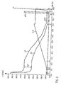
- FIG. 3 shows in a time-pressure diagram, the course of the pressure in the two chambers 4, 5 in a cycle of the method according to the invention.
- two proportional valves are provided, namely the supply air valve 13 and the bypass valve 26 in which the two chambers 4, 5 connecting bypass.
- p4 represents the course of the pressure in the large chamber 4
- p5 the course of the pressure in the small chamber 5
- p22 the pressure exerted by the sealing tools 22, 23 pressure.
- the curve S13 represents no pressure, but the position of the supply air valve 13, wherein the supply air valve 13 is the more closed, the higher the curve S13 in the diagram of FIG. 3 runs.
- the pressure p5 in the smaller chamber 5 reaches the predetermined final pressure of here 100 mbar. From this point on, the supply air valve will be activated 13 at a constant opening width or at constant Zu Kunststoffrate and a differential pressure Ap2 between the two chambers 4, 5 is maintained. Between times t6 (at about 54 seconds) and t7 (at about 56 seconds), the packaging 2 is sealed by applying a pressure p22 by means of the sealing tools 22, 23 to which a sealing pressure is applied by means of a sealing membrane (not shown). Subsequently, a venting and opening of the chambers 4, 5 instead, until they have reached normal pressure again at the time t8 and the sealed package 2 can be removed from the packaging machine 1. This completes a complete work cycle.
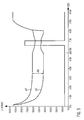
- FIG. 4 shows in a further time-pressure diagram, how the pressures p4, p5 in the two chambers 4, 5 behave when the bypass valve 26 is gradually opened during the evacuation of the two chambers 4, 5.
- This opening of the bypass valve 26 causes the differential pressure ⁇ p between the two pressures p4, p5 to gradually decrease. From the comparison of Figures 3 and 4 shows that the position of the supply air valve 13 determines the final pressure reached in the two chambers 4, 5 or the final vacuum, while the position of the bypass valve 26 determines the prevailing between the two chambers 4, 5 differential pressure Ap.
- FIG. 5 shows in a time-pressure diagram, a problematic situation that may occur without appropriate precautions in certain exceptional situations in the operation of the packaging machine 1 according to the invention. Shown again are the course of the pressures p4, p5 in the two chambers 4, 5, which are initially similar to those in FIG FIG. 3 kick off. At a time t9, however, the lid of the chambers 4, 5 starts to deform due to the pressure building up through the sealing membrane. This deformation causes the suspended on the lid parts of the partition wall 6, so that at one time increases the opening surface of the gap 7.
- the gap forming part of the partition 6 can be suspended resiliently. In this way, a deflection of the lid of the packaging machine 1 during the build-up of the sealing pressure can be compensated by the membrane, so that the cross-sectional area of the gap 7 does not change, even if the Cover deformed.
- the result is in FIG. 6 to see: under the same conditions as in FIG. 5 This time the differential pressure ⁇ p between the two pressures p4, p5 in the two chambers 4, 5 does not collapse.
- the gap 7 can be kept constant, for example, at a gap height of 0.5 mm.
Landscapes
- Chemical & Material Sciences (AREA)
- Dispersion Chemistry (AREA)
- Engineering & Computer Science (AREA)
- Mechanical Engineering (AREA)
- Vacuum Packaging (AREA)
Priority Applications (1)
| Application Number | Priority Date | Filing Date | Title |
|---|---|---|---|
| US13/327,876 US9073654B2 (en) | 2010-12-21 | 2011-12-16 | Packaging machine and method of forming a vacuum package |
Applications Claiming Priority (1)
| Application Number | Priority Date | Filing Date | Title |
|---|---|---|---|
| DE102010055438A DE102010055438A1 (de) | 2010-12-21 | 2010-12-21 | Verpackungsmaschine und Verfahren zum Erzeugen einer Vakuumverpackung |
Publications (2)
| Publication Number | Publication Date |
|---|---|
| EP2468638A1 true EP2468638A1 (fr) | 2012-06-27 |
| EP2468638B1 EP2468638B1 (fr) | 2013-07-10 |
Family
ID=44785127
Family Applications (1)
| Application Number | Title | Priority Date | Filing Date |
|---|---|---|---|
| EP20110007717 Active EP2468638B1 (fr) | 2010-12-21 | 2011-09-22 | Machine d'emballage et procédé de production d'un emballage sous vide |
Country Status (4)
| Country | Link |
|---|---|
| US (1) | US9073654B2 (fr) |
| EP (1) | EP2468638B1 (fr) |
| DE (1) | DE102010055438A1 (fr) |
| ES (1) | ES2426333T3 (fr) |
Cited By (3)
| Publication number | Priority date | Publication date | Assignee | Title |
|---|---|---|---|---|
| EP3239061A1 (fr) * | 2016-04-28 | 2017-11-01 | MULTIVAC Sepp Haggenmüller SE & Co. KG | Machine d'emballage dotee d'un appareil de thermoscellage comprenant un etranglement a vide asservi a la pression |
| WO2018091655A1 (fr) | 2016-11-18 | 2018-05-24 | Cryovac, Inc. | Procédé et appareil de mise sous vide d'emballages |
| EP4082924A1 (fr) * | 2021-04-29 | 2022-11-02 | MULTIVAC Sepp Haggenmüller SE & Co. KG | Scelleuse permettant de sceller les emballages |
Families Citing this family (12)
| Publication number | Priority date | Publication date | Assignee | Title |
|---|---|---|---|---|
| JP5575827B2 (ja) * | 2012-03-27 | 2014-08-20 | 株式会社Tosei | 真空包装方法、および、真空包装装置 |
| ES2392290B1 (es) * | 2012-08-21 | 2013-09-18 | Immobles Del Segria, S.L. | Procedimiento de envasado al vacío de alimentos |
| DE102012017827B4 (de) * | 2012-09-10 | 2021-07-15 | Multivac Sepp Haggenmüller Se & Co. Kg | Verfahren zum Betrieb einer Kammermaschine |
| WO2016071160A1 (fr) | 2014-11-05 | 2016-05-12 | Cryovac, Inc. | Processus et appareil pour extraction de gaz dans un emballage |
| NL2014811B1 (nl) * | 2015-05-16 | 2017-01-31 | Bergwerff Frederik | Werkwijze en inrichting voor het verpakken van een of meer met tabak gevulde dozen in een kunststof zak. |
| EP3581502B1 (fr) | 2015-09-25 | 2020-12-09 | Cryovac, LLC | Soupape rotative de vide et procédé de surveillance du vide |
| MX2018005870A (es) | 2015-11-10 | 2018-08-15 | Cryovac Inc | Aparato y proceso para la evacuacion de paquetes. |
| DE102018116507A1 (de) * | 2018-07-09 | 2020-01-09 | Weber Maschinenbau Gmbh Breidenbach | Verpackungsmaschine mit Siegelstation |
| CN109110181B (zh) * | 2018-10-15 | 2020-08-18 | 重庆电子工程职业学院 | 一种计算机主板真空包装机 |
| CN112849573B (zh) * | 2020-12-31 | 2023-02-17 | 广州亚俊氏电器有限公司 | 一种真空包装方法及真空包装装置 |
| US11542050B2 (en) * | 2021-02-08 | 2023-01-03 | Bonsen Electronics Limited | Vacuum sealing machine driven by air pressure |
| CN112937987A (zh) * | 2021-02-10 | 2021-06-11 | 广州亚俊氏电器有限公司 | 一种多功能真空包装机 |
Citations (4)
| Publication number | Priority date | Publication date | Assignee | Title |
|---|---|---|---|---|
| EP0077458A1 (fr) * | 1981-10-16 | 1983-04-27 | W.R. Grace & Co. | Procédé et dispositif pour l'emballage sous vide |
| DE3411917A1 (de) | 1984-03-30 | 1985-10-03 | Multivac Sepp Haggenmüller KG, 8941 Wolfertschwenden | Verfahren und vorrichtung zum verpacken von gegenstaenden |
| US20030046907A1 (en) * | 2001-08-08 | 2003-03-13 | Costello Anthony William | Packaging apparatus |
| EP1564147A1 (fr) | 2004-02-13 | 2005-08-17 | Cryovac, Inc. | Dispositif et procédé d'emballage sous vide |
Family Cites Families (7)
| Publication number | Priority date | Publication date | Assignee | Title |
|---|---|---|---|---|
| US3832824A (en) * | 1973-06-29 | 1974-09-03 | Grace W R & Co | Apparatus and method for evacuating packages |
| US3965646A (en) * | 1975-02-26 | 1976-06-29 | W. R. Grace & Co. | Adjustable sealing device |
| US4779398A (en) * | 1987-02-06 | 1988-10-25 | W. R. Grace & Co.-Conn., Cryovac Div. | Method and apparatus for making gas flushed packages |
| DE3916170A1 (de) | 1989-05-18 | 1990-11-22 | Multivac Haggenmueller Kg | Vakuum-kammermaschine |
| JP2004067190A (ja) * | 2002-08-07 | 2004-03-04 | Shikoku Kakoki Co Ltd | 包装機械における駆動装置 |
| DE102004024480A1 (de) * | 2004-05-14 | 2005-12-08 | Felix Rudolf Bilz | Verfahren und Vorrichtung zum Evakuieren einer Kammer |
| DE102006047378A1 (de) * | 2006-10-06 | 2008-04-10 | Robert Bosch Gmbh | Ultraschallschweißvorrichtung sowie Verpackungsmaschine mit Ultraschallschweißvorrichtung |
-
2010
- 2010-12-21 DE DE102010055438A patent/DE102010055438A1/de not_active Withdrawn
-
2011
- 2011-09-22 ES ES11007717T patent/ES2426333T3/es active Active
- 2011-09-22 EP EP20110007717 patent/EP2468638B1/fr active Active
- 2011-12-16 US US13/327,876 patent/US9073654B2/en active Active
Patent Citations (4)
| Publication number | Priority date | Publication date | Assignee | Title |
|---|---|---|---|---|
| EP0077458A1 (fr) * | 1981-10-16 | 1983-04-27 | W.R. Grace & Co. | Procédé et dispositif pour l'emballage sous vide |
| DE3411917A1 (de) | 1984-03-30 | 1985-10-03 | Multivac Sepp Haggenmüller KG, 8941 Wolfertschwenden | Verfahren und vorrichtung zum verpacken von gegenstaenden |
| US20030046907A1 (en) * | 2001-08-08 | 2003-03-13 | Costello Anthony William | Packaging apparatus |
| EP1564147A1 (fr) | 2004-02-13 | 2005-08-17 | Cryovac, Inc. | Dispositif et procédé d'emballage sous vide |
Cited By (3)
| Publication number | Priority date | Publication date | Assignee | Title |
|---|---|---|---|---|
| EP3239061A1 (fr) * | 2016-04-28 | 2017-11-01 | MULTIVAC Sepp Haggenmüller SE & Co. KG | Machine d'emballage dotee d'un appareil de thermoscellage comprenant un etranglement a vide asservi a la pression |
| WO2018091655A1 (fr) | 2016-11-18 | 2018-05-24 | Cryovac, Inc. | Procédé et appareil de mise sous vide d'emballages |
| EP4082924A1 (fr) * | 2021-04-29 | 2022-11-02 | MULTIVAC Sepp Haggenmüller SE & Co. KG | Scelleuse permettant de sceller les emballages |
Also Published As
| Publication number | Publication date |
|---|---|
| DE102010055438A1 (de) | 2012-06-21 |
| US20120174531A1 (en) | 2012-07-12 |
| EP2468638B1 (fr) | 2013-07-10 |
| ES2426333T3 (es) | 2013-10-22 |
| US9073654B2 (en) | 2015-07-07 |
Similar Documents
| Publication | Publication Date | Title |
|---|---|---|
| EP2468638B1 (fr) | Machine d'emballage et procédé de production d'un emballage sous vide | |
| EP2011734B1 (fr) | Machine d'emballage et procédé de fabrication d'emballage à partir d'une feuille | |
| DE69104367T2 (de) | Ausgabeverfahren und -vorrichtung, insbesondere für dichtungs-/klebemittel. | |
| DE1933494C3 (de) | Steuereinrichtung an einer Vorrichtung zum Ausbauchen von hohlen Körpern aus Metall | |
| WO2001081027A1 (fr) | Procede et systeme d'entrainement destines a la commande/regulation du mouvement lineaire de compression/coulee | |
| EP2876341A1 (fr) | Procédé de fonctionnement d'une soupape | |
| AT516316B1 (de) | Verfahren zur Steuerung einer hydraulisch angetriebenen Maschine | |
| WO2012100789A1 (fr) | Machine à coulée sous pression sous vide | |
| DE10043209A1 (de) | Flexibles Werkzeug zur Umformung eines Werkstücks | |
| CH702217B1 (de) | Verfahren und Vorrichtung zum Steuern von verschiedenen Prozessphasen einer Einspritzschnecke oder eines Schmelzekolbens einer Spritzgiessmaschine. | |
| EP3508432A1 (fr) | Machine d'emballage pourvue de dispositif de régulation de pression et procédé | |
| EP2086844A1 (fr) | Machine d'emballage à entraînement pneumatique/hydraulique ajustable | |
| WO2017037229A1 (fr) | Procede et dispositif pour la fabrication de pièces en matériau synthétique renforcées par des fibres | |
| EP3587286B1 (fr) | Procédé de détermination de paramètres de processus sur une machine d'emballage | |
| EP1656224B1 (fr) | Systeme pour commander le processus d'etirage dans une presse de transfert | |
| WO2020074588A1 (fr) | Dispositif de déplacement, dispositif de manipulation de pneumatique et procédé de fonctionnement d'un actionneur fluidique | |
| WO2016107677A1 (fr) | Procédé de fabrication de récipients contenant une matière de charge liquide à partir d'ébauches constituées d'une matière thermoplastique et dispositif à cet effet | |
| DE102016113294A1 (de) | Hydraulische Antriebseinrichtung | |
| EP2588261B1 (fr) | Procédé pour remplir la cavité de moulage d'un dispositif de moulage sous pression, ensemble de soupapes et dispositif de moulage sous pression pour la mise en oeuvre du procédé | |
| DE102016001039B4 (de) | Verfahren zum Betrieb eines Einspritzaggregats und Einspritzaggregat | |
| WO2016207059A1 (fr) | Machine d'emballage comprenant un dispositif d'étranglement à moteur | |
| WO2021228482A1 (fr) | Procédé de commande d'un système partiellement électronique | |
| WO2015169830A1 (fr) | Machine d'emballage comprenant un module de commande de dépression constitué de blocs à soupapes homogènes | |
| AT408541B (de) | Anlage zur druckabsenkung in den arbeitskammern mehrerer an eine vakuumzentralanlage angeschlossener verbraucher | |
| WO2018099710A1 (fr) | Procédé permettant de faire fonctionner un système de pompage à vide |
Legal Events
| Date | Code | Title | Description |
|---|---|---|---|
| AK | Designated contracting states |
Kind code of ref document: A1 Designated state(s): AL AT BE BG CH CY CZ DE DK EE ES FI FR GB GR HR HU IE IS IT LI LT LU LV MC MK MT NL NO PL PT RO RS SE SI SK SM TR |
|
| AX | Request for extension of the european patent |
Extension state: BA ME |
|
| PUAI | Public reference made under article 153(3) epc to a published international application that has entered the european phase |
Free format text: ORIGINAL CODE: 0009012 |
|
| 17P | Request for examination filed |
Effective date: 20121001 |
|
| GRAP | Despatch of communication of intention to grant a patent |
Free format text: ORIGINAL CODE: EPIDOSNIGR1 |
|
| RIC1 | Information provided on ipc code assigned before grant |
Ipc: B65B 31/02 20060101AFI20130213BHEP |
|
| GRAS | Grant fee paid |
Free format text: ORIGINAL CODE: EPIDOSNIGR3 |
|
| GRAA | (expected) grant |
Free format text: ORIGINAL CODE: 0009210 |
|
| AK | Designated contracting states |
Kind code of ref document: B1 Designated state(s): AL AT BE BG CH CY CZ DE DK EE ES FI FR GB GR HR HU IE IS IT LI LT LU LV MC MK MT NL NO PL PT RO RS SE SI SK SM TR |
|
| REG | Reference to a national code |
Ref country code: GB Ref legal event code: FG4D Free format text: NOT ENGLISH |
|
| REG | Reference to a national code |
Ref country code: CH Ref legal event code: NV Representative=s name: BOVARD AG, CH Ref country code: CH Ref legal event code: EP Ref country code: AT Ref legal event code: REF Ref document number: 620824 Country of ref document: AT Kind code of ref document: T Effective date: 20130715 |
|
| REG | Reference to a national code |
Ref country code: IE Ref legal event code: FG4D Free format text: LANGUAGE OF EP DOCUMENT: GERMAN |
|
| REG | Reference to a national code |
Ref country code: DE Ref legal event code: R096 Ref document number: 502011000998 Country of ref document: DE Effective date: 20130905 |
|
| REG | Reference to a national code |
Ref country code: NL Ref legal event code: T3 |
|
| REG | Reference to a national code |
Ref country code: ES Ref legal event code: FG2A Ref document number: 2426333 Country of ref document: ES Kind code of ref document: T3 Effective date: 20131022 |
|
| PG25 | Lapsed in a contracting state [announced via postgrant information from national office to epo] |
Ref country code: SI Free format text: LAPSE BECAUSE OF FAILURE TO SUBMIT A TRANSLATION OF THE DESCRIPTION OR TO PAY THE FEE WITHIN THE PRESCRIBED TIME-LIMIT Effective date: 20130710 |
|
| REG | Reference to a national code |
Ref country code: LT Ref legal event code: MG4D |
|
| PG25 | Lapsed in a contracting state [announced via postgrant information from national office to epo] |
Ref country code: CY Free format text: LAPSE BECAUSE OF FAILURE TO SUBMIT A TRANSLATION OF THE DESCRIPTION OR TO PAY THE FEE WITHIN THE PRESCRIBED TIME-LIMIT Effective date: 20130828 Ref country code: HR Free format text: LAPSE BECAUSE OF FAILURE TO SUBMIT A TRANSLATION OF THE DESCRIPTION OR TO PAY THE FEE WITHIN THE PRESCRIBED TIME-LIMIT Effective date: 20130710 Ref country code: LT Free format text: LAPSE BECAUSE OF FAILURE TO SUBMIT A TRANSLATION OF THE DESCRIPTION OR TO PAY THE FEE WITHIN THE PRESCRIBED TIME-LIMIT Effective date: 20130710 Ref country code: PT Free format text: LAPSE BECAUSE OF FAILURE TO SUBMIT A TRANSLATION OF THE DESCRIPTION OR TO PAY THE FEE WITHIN THE PRESCRIBED TIME-LIMIT Effective date: 20131111 Ref country code: NO Free format text: LAPSE BECAUSE OF FAILURE TO SUBMIT A TRANSLATION OF THE DESCRIPTION OR TO PAY THE FEE WITHIN THE PRESCRIBED TIME-LIMIT Effective date: 20131010 Ref country code: IS Free format text: LAPSE BECAUSE OF FAILURE TO SUBMIT A TRANSLATION OF THE DESCRIPTION OR TO PAY THE FEE WITHIN THE PRESCRIBED TIME-LIMIT Effective date: 20131110 Ref country code: SE Free format text: LAPSE BECAUSE OF FAILURE TO SUBMIT A TRANSLATION OF THE DESCRIPTION OR TO PAY THE FEE WITHIN THE PRESCRIBED TIME-LIMIT Effective date: 20130710 |
|
| PG25 | Lapsed in a contracting state [announced via postgrant information from national office to epo] |
Ref country code: LV Free format text: LAPSE BECAUSE OF FAILURE TO SUBMIT A TRANSLATION OF THE DESCRIPTION OR TO PAY THE FEE WITHIN THE PRESCRIBED TIME-LIMIT Effective date: 20130710 Ref country code: FI Free format text: LAPSE BECAUSE OF FAILURE TO SUBMIT A TRANSLATION OF THE DESCRIPTION OR TO PAY THE FEE WITHIN THE PRESCRIBED TIME-LIMIT Effective date: 20130710 Ref country code: PL Free format text: LAPSE BECAUSE OF FAILURE TO SUBMIT A TRANSLATION OF THE DESCRIPTION OR TO PAY THE FEE WITHIN THE PRESCRIBED TIME-LIMIT Effective date: 20130710 Ref country code: GR Free format text: LAPSE BECAUSE OF FAILURE TO SUBMIT A TRANSLATION OF THE DESCRIPTION OR TO PAY THE FEE WITHIN THE PRESCRIBED TIME-LIMIT Effective date: 20131011 |
|
| BERE | Be: lapsed |
Owner name: MULTIVAC SEPP HAGGENMULLER G.M.B.H. & CO KG Effective date: 20130930 |
|
| PG25 | Lapsed in a contracting state [announced via postgrant information from national office to epo] |
Ref country code: CY Free format text: LAPSE BECAUSE OF FAILURE TO SUBMIT A TRANSLATION OF THE DESCRIPTION OR TO PAY THE FEE WITHIN THE PRESCRIBED TIME-LIMIT Effective date: 20130710 |
|
| PG25 | Lapsed in a contracting state [announced via postgrant information from national office to epo] |
Ref country code: RO Free format text: LAPSE BECAUSE OF FAILURE TO SUBMIT A TRANSLATION OF THE DESCRIPTION OR TO PAY THE FEE WITHIN THE PRESCRIBED TIME-LIMIT Effective date: 20130710 Ref country code: DK Free format text: LAPSE BECAUSE OF FAILURE TO SUBMIT A TRANSLATION OF THE DESCRIPTION OR TO PAY THE FEE WITHIN THE PRESCRIBED TIME-LIMIT Effective date: 20130710 Ref country code: CZ Free format text: LAPSE BECAUSE OF FAILURE TO SUBMIT A TRANSLATION OF THE DESCRIPTION OR TO PAY THE FEE WITHIN THE PRESCRIBED TIME-LIMIT Effective date: 20130710 Ref country code: EE Free format text: LAPSE BECAUSE OF FAILURE TO SUBMIT A TRANSLATION OF THE DESCRIPTION OR TO PAY THE FEE WITHIN THE PRESCRIBED TIME-LIMIT Effective date: 20130710 Ref country code: MC Free format text: LAPSE BECAUSE OF FAILURE TO SUBMIT A TRANSLATION OF THE DESCRIPTION OR TO PAY THE FEE WITHIN THE PRESCRIBED TIME-LIMIT Effective date: 20130710 Ref country code: SK Free format text: LAPSE BECAUSE OF FAILURE TO SUBMIT A TRANSLATION OF THE DESCRIPTION OR TO PAY THE FEE WITHIN THE PRESCRIBED TIME-LIMIT Effective date: 20130710 |
|
| PLBE | No opposition filed within time limit |
Free format text: ORIGINAL CODE: 0009261 |
|
| STAA | Information on the status of an ep patent application or granted ep patent |
Free format text: STATUS: NO OPPOSITION FILED WITHIN TIME LIMIT |
|
| 26N | No opposition filed |
Effective date: 20140411 |
|
| REG | Reference to a national code |
Ref country code: IE Ref legal event code: MM4A |
|
| REG | Reference to a national code |
Ref country code: DE Ref legal event code: R097 Ref document number: 502011000998 Country of ref document: DE Effective date: 20140411 |
|
| PG25 | Lapsed in a contracting state [announced via postgrant information from national office to epo] |
Ref country code: IE Free format text: LAPSE BECAUSE OF NON-PAYMENT OF DUE FEES Effective date: 20130922 Ref country code: BE Free format text: LAPSE BECAUSE OF NON-PAYMENT OF DUE FEES Effective date: 20130930 |
|
| PG25 | Lapsed in a contracting state [announced via postgrant information from national office to epo] |
Ref country code: SM Free format text: LAPSE BECAUSE OF FAILURE TO SUBMIT A TRANSLATION OF THE DESCRIPTION OR TO PAY THE FEE WITHIN THE PRESCRIBED TIME-LIMIT Effective date: 20130710 |
|
| PG25 | Lapsed in a contracting state [announced via postgrant information from national office to epo] |
Ref country code: TR Free format text: LAPSE BECAUSE OF FAILURE TO SUBMIT A TRANSLATION OF THE DESCRIPTION OR TO PAY THE FEE WITHIN THE PRESCRIBED TIME-LIMIT Effective date: 20130710 Ref country code: MT Free format text: LAPSE BECAUSE OF FAILURE TO SUBMIT A TRANSLATION OF THE DESCRIPTION OR TO PAY THE FEE WITHIN THE PRESCRIBED TIME-LIMIT Effective date: 20130710 |
|
| PG25 | Lapsed in a contracting state [announced via postgrant information from national office to epo] |
Ref country code: RS Free format text: LAPSE BECAUSE OF FAILURE TO SUBMIT A TRANSLATION OF THE DESCRIPTION OR TO PAY THE FEE WITHIN THE PRESCRIBED TIME-LIMIT Effective date: 20131010 Ref country code: HU Free format text: LAPSE BECAUSE OF FAILURE TO SUBMIT A TRANSLATION OF THE DESCRIPTION OR TO PAY THE FEE WITHIN THE PRESCRIBED TIME-LIMIT; INVALID AB INITIO Effective date: 20110922 Ref country code: LU Free format text: LAPSE BECAUSE OF NON-PAYMENT OF DUE FEES Effective date: 20130922 Ref country code: BG Free format text: LAPSE BECAUSE OF FAILURE TO SUBMIT A TRANSLATION OF THE DESCRIPTION OR TO PAY THE FEE WITHIN THE PRESCRIBED TIME-LIMIT Effective date: 20130710 Ref country code: MK Free format text: LAPSE BECAUSE OF FAILURE TO SUBMIT A TRANSLATION OF THE DESCRIPTION OR TO PAY THE FEE WITHIN THE PRESCRIBED TIME-LIMIT Effective date: 20130710 |
|
| REG | Reference to a national code |
Ref country code: DE Ref legal event code: R082 Ref document number: 502011000998 Country of ref document: DE Representative=s name: GRUENECKER PATENT- UND RECHTSANWAELTE PARTG MB, DE Ref country code: DE Ref legal event code: R081 Ref document number: 502011000998 Country of ref document: DE Owner name: MULTIVAC SEPP HAGGENMUELLER SE & CO. KG, DE Free format text: FORMER OWNER: MULTIVAC SEPP HAGGENMUELLER GMBH & CO. KG, 87787 WOLFERTSCHWENDEN, DE |
|
| GBPC | Gb: european patent ceased through non-payment of renewal fee |
Effective date: 20150922 |
|
| PG25 | Lapsed in a contracting state [announced via postgrant information from national office to epo] |
Ref country code: GB Free format text: LAPSE BECAUSE OF NON-PAYMENT OF DUE FEES Effective date: 20150922 |
|
| REG | Reference to a national code |
Ref country code: FR Ref legal event code: PLFP Year of fee payment: 6 |
|
| REG | Reference to a national code |
Ref country code: FR Ref legal event code: PLFP Year of fee payment: 7 |
|
| REG | Reference to a national code |
Ref country code: AT Ref legal event code: MM01 Ref document number: 620824 Country of ref document: AT Kind code of ref document: T Effective date: 20160922 |
|
| PG25 | Lapsed in a contracting state [announced via postgrant information from national office to epo] |
Ref country code: AT Free format text: LAPSE BECAUSE OF NON-PAYMENT OF DUE FEES Effective date: 20160922 |
|
| REG | Reference to a national code |
Ref country code: FR Ref legal event code: PLFP Year of fee payment: 8 |
|
| PG25 | Lapsed in a contracting state [announced via postgrant information from national office to epo] |
Ref country code: AL Free format text: LAPSE BECAUSE OF FAILURE TO SUBMIT A TRANSLATION OF THE DESCRIPTION OR TO PAY THE FEE WITHIN THE PRESCRIBED TIME-LIMIT Effective date: 20130710 |
|
| P01 | Opt-out of the competence of the unified patent court (upc) registered |
Effective date: 20230404 |
|
| PGFP | Annual fee paid to national office [announced via postgrant information from national office to epo] |
Ref country code: NL Payment date: 20230920 Year of fee payment: 13 |
|
| PGFP | Annual fee paid to national office [announced via postgrant information from national office to epo] |
Ref country code: FR Payment date: 20230918 Year of fee payment: 13 |
|
| PGFP | Annual fee paid to national office [announced via postgrant information from national office to epo] |
Ref country code: ES Payment date: 20231019 Year of fee payment: 13 |
|
| REG | Reference to a national code |
Ref country code: NL Ref legal event code: MM Effective date: 20241001 |
|
| PG25 | Lapsed in a contracting state [announced via postgrant information from national office to epo] |
Ref country code: NL Free format text: LAPSE BECAUSE OF NON-PAYMENT OF DUE FEES Effective date: 20241001 |
|
| PG25 | Lapsed in a contracting state [announced via postgrant information from national office to epo] |
Ref country code: FR Free format text: LAPSE BECAUSE OF NON-PAYMENT OF DUE FEES Effective date: 20240930 |
|
| REG | Reference to a national code |
Ref country code: CH Ref legal event code: U11 Free format text: ST27 STATUS EVENT CODE: U-0-0-U10-U11 (AS PROVIDED BY THE NATIONAL OFFICE) Effective date: 20251001 |
|
| PGFP | Annual fee paid to national office [announced via postgrant information from national office to epo] |
Ref country code: DE Payment date: 20250919 Year of fee payment: 15 |
|
| REG | Reference to a national code |
Ref country code: ES Ref legal event code: FD2A Effective date: 20251031 |
|
| PGFP | Annual fee paid to national office [announced via postgrant information from national office to epo] |
Ref country code: IT Payment date: 20250930 Year of fee payment: 15 |
|
| PGFP | Annual fee paid to national office [announced via postgrant information from national office to epo] |
Ref country code: CH Payment date: 20251001 Year of fee payment: 15 |
|
| PG25 | Lapsed in a contracting state [announced via postgrant information from national office to epo] |
Ref country code: ES Free format text: LAPSE BECAUSE OF NON-PAYMENT OF DUE FEES Effective date: 20240923 |