EP2468960B1 - Procédé et appareil de forage de sol - Google Patents
Procédé et appareil de forage de sol Download PDFInfo
- Publication number
- EP2468960B1 EP2468960B1 EP20110195067 EP11195067A EP2468960B1 EP 2468960 B1 EP2468960 B1 EP 2468960B1 EP 20110195067 EP20110195067 EP 20110195067 EP 11195067 A EP11195067 A EP 11195067A EP 2468960 B1 EP2468960 B1 EP 2468960B1
- Authority
- EP
- European Patent Office
- Prior art keywords
- drilling
- tube
- propeller
- ground
- parameters
- Prior art date
- Legal status (The legal status is an assumption and is not a legal conclusion. Google has not performed a legal analysis and makes no representation as to the accuracy of the status listed.)
- Active
Links
Images
Classifications
-
- E—FIXED CONSTRUCTIONS
- E02—HYDRAULIC ENGINEERING; FOUNDATIONS; SOIL SHIFTING
- E02D—FOUNDATIONS; EXCAVATIONS; EMBANKMENTS; UNDERGROUND OR UNDERWATER STRUCTURES
- E02D7/00—Methods or apparatus for placing sheet pile bulkheads, piles, mouldpipes, or other moulds
- E02D7/22—Placing by screwing down
-
- E—FIXED CONSTRUCTIONS
- E21—EARTH OR ROCK DRILLING; MINING
- E21B—EARTH OR ROCK DRILLING; OBTAINING OIL, GAS, WATER, SOLUBLE OR MELTABLE MATERIALS OR A SLURRY OF MINERALS FROM WELLS
- E21B44/00—Automatic control systems specially adapted for drilling operations, i.e. self-operating systems which function to carry out or modify a drilling operation without intervention of a human operator, e.g. computer-controlled drilling systems; Systems specially adapted for monitoring a plurality of drilling variables or conditions
-
- E—FIXED CONSTRUCTIONS
- E21—EARTH OR ROCK DRILLING; MINING
- E21B—EARTH OR ROCK DRILLING; OBTAINING OIL, GAS, WATER, SOLUBLE OR MELTABLE MATERIALS OR A SLURRY OF MINERALS FROM WELLS
- E21B7/00—Special methods or apparatus for drilling
- E21B7/20—Driving or forcing casings or pipes into boreholes, e.g. sinking; Simultaneously drilling and casing boreholes
- E21B7/201—Driving or forcing casings or pipes into boreholes, e.g. sinking; Simultaneously drilling and casing boreholes with helical conveying means
Definitions
- the present invention relates to a method and an apparatus for drilling the ground, wherein the actual energy required by the drilling process is calculated by measuring drilling parameters. Said method is applicable, in particular, to the installation of foundation piles in the ground.
- the present invention relates to a method and an apparatus for the installation of piles in the ground in accordance with the CAP (Cased Augered Piles) and CSP (Cased Secant Piles) technologies.
- CAP Content Augered Piles
- CSP Content Secant Piles
- These technologies employ an excavation equipment consisting of a continuous ground drilling propeller housed inside a covering tube, the main purpose of which is to stabilize the borehole walls and to allow advancement into particularly hard ground.
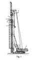
- said equipment comprises a drilling machine like the one shown in Fig. 1 , which is typically tracked and comprises a drilling turret 2 with a vertical guiding antenna 3 and at least one rotary head for driving drilling batteries, which are slideable along the antenna and are driven by a mechanism (generally a rope mechanism) capable of exerting a pull and a thrust onto the batteries.
- a drilling machine like the one shown in Fig. 1 , which is typically tracked and comprises a drilling turret 2 with a vertical guiding antenna 3 and at least one rotary head for driving drilling batteries, which are slideable along the antenna and are driven by a mechanism (generally a rope mechanism) capable of exerting a pull and a thrust onto the batteries.
- a mechanism generally a rope mechanism
- First inner drive means are connected to a propeller battery 5, and second independent external drive means are connected to tube 7, for the purpose of selectively rotating the two elements.
- the inner drive means belong to a higher first rotary head 4, whereas the external drive means are connected to a lower second rotary head 6.
- the propeller and the tube are preferably rotated in a discordant manner, preferably the tube rotating counterclockwise and the propeller rotating clockwise.
- the propeller and the tube can move axially relative to each other by means of suitable selective drive means.
- the main function of the covering tube is to stabilize the borehole walls and to allow advancement into particularly hard ground while maintaining a high degree of borehole verticality.
- the covering hole is also fitted with excavating teeth at the bottom edge to bite the ground in the annular excavation portion.
- the rotations must advantageously occur in opposite directions to allow the ground to climb up along the propeller because of the inner friction between the material and the tube wall, to be then discharged in the upper part of the covering tube.
- the excavation equipment further comprises a driving cab 8 for an operator, which includes all the manipulators for operating the machine and the systems for displaying and controlling the most important parameters.
- Patent EP1942247 describes a method and a device for compaction drilling, wherein a drilling tool is fed into the ground through the effect of the thrust and rotation generated by suitable means.
- the operating drilling parameters (torque, revolution speed, descent speed per revolution, constituting the alpha and thrust parameters) are measured during the drilling process and are simultaneously sent to a computer, which correlates them mathematically to determine the load capacity of an "ideal" pile cast into the borehole just drilled.
- the system calculates the load capacity characteristic, called ⁇ , and enters it into a previously prepared table containing data relating to drilling tests previously carried out in grounds having known characteristics. This ground type estimation also allows establishing the final depth of the pile to be made as a function of the measured values.
- the tool shape is as long as the whole drilling depth, and the resulting frictions are distributed over large and non-negligible contact areas. This differs from what happens when normal excavation tools are used, the height of which is generally limited (they are not taller than 2 m), and which are driven by rods (also telescopic ones) that do not come in contact with the borehole walls.
- the covering tube is filled with ground by the propeller.
- the two excavation batteries tube and propeller
- heavy frictions are generated among the inner surface of the covering tube, the ground contained therein and the continuous propeller.
- the operating machine In order to overcome these frictions, the operating machine must output more torque to the rotary heads, as well as stronger pull or thrust axial forces, if relative axial movements are also desired between the covering tube and the propeller.
- One aspect of the present invention relates to a method having the features set out in the appended claim 1.
- a further aspect of the present invention relates to an apparatus having the features set out in the appended claim 8.
- the drilling equipment essentially comprises at least one drilling turret 2 with a vertical guiding antenna 3, and at least one rotary head for driving the drilling batteries.
- Said batteries comprise at least one continuous ground drilling rotary propeller, housed inside a covering tube 7.
- First inner drive means or a higher first rotary head 4, are adapted to drive said propeller 5, while second independent external means, or a lower second rotary head 6, are connected to tube 7 and allow movement thereof.
- the propeller and the tube can rotate and move axially relative to each other in a selective and independent manner.
- the equipment further comprises a driving cab 8 for an operator, which includes all the manipulators for operating the machine and the systems for displaying the measured parameters.
- the equipment comprises an excavation parameter control system (e.g. a PLC, a computer or, more generally, a data processing unit), which is enabled to receive information from drilling parameter control sensors.
- Said sensors preferably comprise torque sensors, pull-thrust sensors, revolution speed sensors, advancement speed sensors and depth sensors.
- the system is enabled to store data received from the sensors, which data is subjected to mutual or time-based correlation.
- the control system comprises a database storing the data measured by the equipment.
- the system compares the current data with the data stored in the database, and returns the actual values of the measurements, whether direct or indirect (i.e. obtained through formulas), necessary for knowing in advance the characteristics of a portion of ground involved in the excavation.
- the excavation parameter control system can display and/or create graphs of said parameters in the course of the excavation and/or offers the possibility of exporting this information to allow it to be treated through external means (e.g. computer, palmtops, iphone, ipad, etc.). Furthermore, the system can warn the operator when any one of said parameters changes very rapidly and reaches anomalous values beyond a certain user-defined threshold.
- the propeller and the tube are rotated in a discordant manner, preferably the tube rotating counterclockwise and the propeller rotating clockwise.
- the propeller and the tube can be moved axially relative to each other through suitable selective drive means.
- the main purpose of the covering tube is to stabilize the borehole walls and to allow advancement into particularly hard ground.
- the covering tube is also fitted with excavating teeth at the edge to bite the ground in the annular portion. The rotations must take place in opposite directions to allow the ground to climb up along the propeller, due to the internal frictions between the material and the tube wall, to be then discharged in the upper part of the covering tube.
- one method for evaluating the component of internal interaction between the two drilling batteries is to fill the tube with the propeller, so as to simulate the actual behaviour at the end of the excavation, and then to carry out measurements in such conditions by means of the sensors.
- Groundless values will first be measured, so as to determine the energetic characteristics dispersed by the machine, while also taking into account the actual design of the tube and propeller in use, which from case to case may have different tolerances and dimensions, and hence be subject to different friction losses and provide different performance levels, which cannot be easily determined beforehand. It must be pointed out that one such machine can operate within an excavation diameter range of 400 mm to 1,200 mm and, as a consequence, the frictions (which are proportional to the lateral area of the tube) will be very different and will have to be correlated with the actual excavation diameter and length.
- This actual value can be useful to determine the real characteristics of the ground or to analyze the design modifications required for facing any undesired and unexpected conditions when carrying out the excavation.
- the maximum values relating to a full propeller, when, for example, the next drilling operation is carried out without first emptying the propeller.
- the first hole is started with clean batteries, in that case the propeller is loaded progressively in a manner proportional to the depth reached, whereas the second hole can be started with a clean battery (if the operator empties the propeller completely at the end of each drilling operation) or with a partially or completely full battery (so long as the conditions of stability of the equipment allow).
- the method according to the present invention requires a "loadless" measurement of the drilling parameters in order to be able to calculate the energy necessary for rotating the drilling battery.
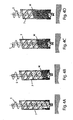
- Said “loadless” measurement (taken with the drilling battery out of the ground) comprises a step of measuring said parameters with the space between the propellers and the tube empty or void of material, followed by a step of measuring said parameters at least once with a predetermined intermediate quantity of material therein, so as to simulate the excavation process in an intermediate position.
- this "loadless” measurement preferably also comprises a step of measuring said parameters with the space between the propellers and the tube completely filled with material, thus simulating the end-of-excavation conditions.
- the "loadless" drilling parameter measurement step should include the possibility of filling the space between the propeller and the tube with a material similar to that of the drilling site.
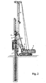
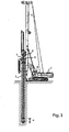
- the present invention provides for executing a ground drilling operation with the drilling battery by placing the propeller at a predetermined height advanced with respect to the tube, e.g. by 0.1 m - 1 m.
- a predetermined height advanced with respect to the tube, e.g. by 0.1 m - 1 m.
- the drilling operation carried out by the propeller will end at the preset depth (H in Fig. 3 ), obtained by imposing a predetermined value (to be recorded), e.g. by correlating it with the excavation diameter and imposing a predefined volume (e.g. one cubic metre) for the testing step.
- the excavation tool can be configured in both the propeller and the tube.
- the excavation tool can be configured in both the propeller and the tube.
- the present invention allows to determine the actual excavation parameters when more than one battery is used, as well as to determine the specific energy of drilling when elongated batteries are employed.
Landscapes
- Engineering & Computer Science (AREA)
- Life Sciences & Earth Sciences (AREA)
- Mining & Mineral Resources (AREA)
- Geology (AREA)
- General Life Sciences & Earth Sciences (AREA)
- Environmental & Geological Engineering (AREA)
- Fluid Mechanics (AREA)
- Physics & Mathematics (AREA)
- Geochemistry & Mineralogy (AREA)
- Paleontology (AREA)
- Civil Engineering (AREA)
- General Engineering & Computer Science (AREA)
- Structural Engineering (AREA)
- Earth Drilling (AREA)
- Investigation Of Foundation Soil And Reinforcement Of Foundation Soil By Compacting Or Drainage (AREA)
Claims (11)
- Procédé de forage du sol à l'aide d'un équipement d'excavation, en particulier pour l'installation de piliers de fondation, ledit équipement comprenant :. au moins une tour de forage (2) munie d'une antenne de guidage vertical (3), au moins une tête rotative permettant d'entrainer des batteries de forage comprenant au moins une vis sans fin rotative pour le forage en continu du sol (5) logée à l'intérieur d'un tube de protection (7),. des premiers moyens d'entraînement internes conçus pour entrainer ladite vis sans fin (5),. des seconds moyens d'entraînement raccordés au tube (7) et permettant son déplacement,. la vis sans fin et le tube étant capables de tourner et de se déplacer axialement l'un par rapport à l'autre de manière sélective et indépendante,. une cabine de conduite (8) pour un opérateur, équipée de toutes les manettes permettant de faire fonctionner la machine et les systèmes permettant d'afficher et de commander les paramètres mesurés,. des capteurs conçus pour mesurer les paramètres de forage,ledit procédé étant caractérisé en ce qu'il comprend les étapes suivantes :. forage du sol à une profondeur prédéterminée grâce à la batterie de forage, en plaçant la vis sans fin à une hauteur prédéterminée avancée par rapport au tube et en faisant tourner et avancer la vis sans fin intérieure,. mesure desdits paramètres de forage afin de déterminer l'énergie totale requise par le processus de forage, afin d'obtenir des informations concernant la consistance réelle du sol.
- Procédé selon la revendication 1, dans lequel, après détermination de l'énergie totale requise par le processus de forage, l'énergie réelle est calculée en soustrayant de l'énergie totale les contributions énergétiques dues aux frottements déterminés préalablement grâce à des essais « à vide ».
- Procédé selon la revendication 1, dans lequel, lorsque la vis sans fin est en rotation, le tube reste fixe.
- Procédé selon la revendication 1, comprenant en outre les étapes de :. relevage de la vis sans fin afin de la replacer au moins partiellement à l'intérieur du tube, et. mesure des paramètres de forage « à vide » après ladite étape de relevage.
- Procédé de forage du sol à l'aide d'un équipement d'excavation ayant les caractéristiques de l'équipement selon la revendication 1, caractérisé en ce qu'il comprend les étapes suivantes :. mesure des paramètres de forage « à vide », afin de calculer l'énergie requise pour maintenir la batterie de forage en rotation,. insertion de la batterie de forage dans le sol qui doit être excavé,. mesure des paramètres de forage en cours d'utilisation pendant ladite étape d'excavation en cours,. soustraction des valeurs « à vide » mesurées des valeurs en cours d'utilisation,. calcul de l'énergie réelle requise pour mener à bien le processus de forage, afin d'obtenir des informations concernant la consistance réelle du sol.
- Procédé selon la revendication 5, dans lequel ladite étape de mesure « à vide » comprend les étapes de :. mise en rotation soit de la vis sans fin, soit du tube, soit des deux, alors que la batterie de forage est hors du sol,. mesure desdits paramètres de forage, l'espace entre la vis sans fin et le tube étant vide de matériau,. mesure desdits paramètres de forage au moins une fois avec une quantité intermédiaire prédéterminée de matériau à l'intérieur de l'équipement, de manière à simuler l'étape d'excavation dans une position intermédiaire.
- Procédé selon la revendication 5, dans lequel ladite étape de mesure « à vide » comprend l'étape de mesure desdits paramètres de forage, l'espace entre la vis sans fin et le tube étant complètement rempli de matériau, tout en mettant en rotation soit la vis sans fin soit le tube, soit les deux.
- Procédé selon la revendication 1 comprenant en outre les étapes de :. relevage du bout du tube du fond du trou, de manière à éviter tout contact de la tête, et mise en rotation de la même manière à la fois du tube et de la vis sans fin, et. mesure des paramètres de forage et calcul de la valeur de l'énergie requise pour surmonter les frottements extérieurs entre le tube et le trou de forage.
- Procédé selon les revendications précédentes, dans lequel lesdits paramètres de forage sont choisis parmi le groupe suivant de paramètres : couple, tirage/poussée, vitesse de révolution, vitesse d'avancée et profondeur atteinte.
- Appareil de forage du sol, en particulier pour l'installation de piliers de fondation, comprenant :. au moins une tour de forage (2) munie d'une antenne de guidage vertical (3), au moins une tête rotative permettant d'entrainer des batteries de forage comprenant au moins une vis sans fin rotative pour le forage en continu du sol (5) logée à l'intérieur d'un tube de protection (7),. des premiers moyens d'entraînement internes conçus pour entrainer ladite vis sans fin (5),. des seconds moyens d'entraînement raccordés au tube (7) et permettant son déplacement,. une cabine de conduite (8) pour un opérateur, équipée de toutes les manettes permettant de faire fonctionner la machine et les systèmes permettant d'afficher et de commander les paramètres mesurés,. un système de commande des paramètres d'excavation, qui est activé pour recevoir des informations transmises par les capteurs de commande des paramètres de forage,caractérisé en ce que ladite vis sans fin et ledit tube peuvent se déplacer axialement l'un par rapport à l'autre, de telle sorte que le sol puisse être foré à une profondeur prédéterminée grâce à la batterie de forage, en plaçant la vis sans fin à une hauteur prédéterminée avancée par rapport au tube et en faisant tourner uniquement la vis sans fin intérieure, de manière à être capable de mesurer lesdits paramètres de forage et de calculer l'énergie totale nécessaire pour mener à bien l'excavation afin d'obtenir des informations concernant la consistance réelle du sol.
- Appareil selon la revendication 10, dans lequel lesdits capteurs de commande sont choisis parmi le groupe suivant de capteurs : capteurs de couple, capteurs de tirage/poussée, capteurs de vitesse de révolution, capteurs de vitesse, capteurs d'avancée et capteurs de profondeur.
Applications Claiming Priority (1)
| Application Number | Priority Date | Filing Date | Title |
|---|---|---|---|
| ITTO2010A001047A IT1403419B1 (it) | 2010-12-23 | 2010-12-23 | Metodo ed apparato per la perforazione del terreno. |
Publications (2)
| Publication Number | Publication Date |
|---|---|
| EP2468960A1 EP2468960A1 (fr) | 2012-06-27 |
| EP2468960B1 true EP2468960B1 (fr) | 2015-01-14 |
Family
ID=43737436
Family Applications (1)
| Application Number | Title | Priority Date | Filing Date |
|---|---|---|---|
| EP20110195067 Active EP2468960B1 (fr) | 2010-12-23 | 2011-12-22 | Procédé et appareil de forage de sol |
Country Status (3)
| Country | Link |
|---|---|
| US (1) | US8821072B2 (fr) |
| EP (1) | EP2468960B1 (fr) |
| IT (1) | IT1403419B1 (fr) |
Families Citing this family (15)
| Publication number | Priority date | Publication date | Assignee | Title |
|---|---|---|---|---|
| FR2999200B1 (fr) * | 2012-12-11 | 2015-02-06 | Soletanche Freyssinet | Outil melangeur pour le traitement d'une portion de sol |
| NL2011003C2 (en) * | 2013-06-18 | 2014-12-22 | Ihc Hydrohammer B V | Pile driving methods and systems. |
| GB2525147B (en) * | 2014-01-27 | 2020-09-09 | Mmi Engineering Ltd | Pile insertion |
| JP6618253B2 (ja) * | 2014-12-17 | 2019-12-11 | 日本車輌製造株式会社 | 施工具駆動用油圧装置 |
| JP6508936B2 (ja) * | 2014-12-19 | 2019-05-08 | 日本車輌製造株式会社 | 杭打機 |
| DE102015105908B4 (de) * | 2015-04-17 | 2024-08-01 | Bauer Maschinen Gmbh | Bohrgerät zum Erstellen einer verrohrten Bohrung und Verfahren zum Betreiben eines Bohrgerätes |
| IT201700024727A1 (it) * | 2017-03-06 | 2018-09-06 | Soilmec Spa | Gruppo modulare di movimentazione di attrezzature di scavo per macchine di scavo, macchina di scavo, metodo per convertire la configurazione di scavo di una macchina di scavo. |
| PL3467205T3 (pl) * | 2017-10-06 | 2020-06-01 | Bauer Maschinen Gmbh | Sposób wytwarzania pala w gruncie i urządzenie do obrabiania gruntu dla niego |
| US11008849B2 (en) * | 2018-09-05 | 2021-05-18 | Deere & Company | Grade management system for an implement |
| EP3663503B1 (fr) * | 2018-12-05 | 2021-01-06 | ABI Anlagentechnik-Baumaschinen-Industriebedarf Maschinenfabrik und Vertriebsgesellschaft mbH | Appareil de forage du sol |
| CN110159192B (zh) * | 2019-04-29 | 2020-07-07 | 江苏科弘岩土工程有限公司 | 一种液压步履式螺旋打桩机 |
| US10914046B1 (en) * | 2020-08-11 | 2021-02-09 | Jamal Nasir | System, apparatus, and method for installing a foundation |
| JP7337343B2 (ja) * | 2021-01-27 | 2023-09-04 | 株式会社R&Tグループ | 防護柵の支柱施工装置と支柱施工方法 |
| CN113931572B (zh) * | 2021-09-22 | 2024-01-19 | 中交路桥华南工程有限公司 | 复合地层大直径桩基的施工方法及钻头系统 |
| IT202200021888A1 (it) | 2022-10-24 | 2024-04-24 | Soilmec Spa | Procedimento, sistema e programma per elaboratore per sorvegliare un dispositivo da sorvegliare quale per esempio una fresa per diaframmi, perforatrice per pali e altre fondazioni e altre macchine operatrici. |
Family Cites Families (11)
| Publication number | Priority date | Publication date | Assignee | Title |
|---|---|---|---|---|
| FR2601397B1 (fr) * | 1986-07-11 | 1989-07-28 | Technologies Speciales Ingenie | Procede et dispositif de battage pour enfoncer des outils dans le sol. |
| JPH0711233B2 (ja) * | 1991-08-05 | 1995-02-08 | 信 高橋 | 基礎杭の無排土施工装置および基礎杭の無排土施工方法 |
| JPH09125854A (ja) * | 1995-11-06 | 1997-05-13 | Ishioka Kensetsu Kk | オールケーシング掘削機による掘削孔の鉛直精度管理方法 |
| US6033152A (en) * | 1997-04-11 | 2000-03-07 | Berkel & Company Contractors, Inc. | Pile forming apparatus |
| JP3837714B2 (ja) * | 1997-07-16 | 2006-10-25 | 三和機材株式会社 | 地盤改良柱体造成機 |
| JPH11200749A (ja) | 1998-01-14 | 1999-07-27 | Kinki Ishiko Kk | 基礎工事用機械における排土装置 |
| DE20101657U1 (de) | 2001-01-30 | 2001-04-19 | DELMAG GmbH & Co. KG, 73730 Esslingen | Bohrgerät |
| GB2377235A (en) * | 2001-07-17 | 2003-01-08 | Cie Du Sol | Drilling tool |
| CN1944939B (zh) * | 2006-11-09 | 2012-09-05 | 山河智能装备股份有限公司 | 分离驱动式套管螺旋钻机及其施工方法 |
| ES2323023T3 (es) * | 2007-01-04 | 2009-07-03 | Bauer Maschinen Gmbh | Procedimiento y dispositivo para la realizacion de una perforacion en el suelo mediante perforacion por desplazamiento. |
| JP5086791B2 (ja) | 2007-12-19 | 2012-11-28 | 株式会社カネカ | 空気入りタイヤ用インナーライナー用組成物および空気入りタイヤ用インナーライナー |
-
2010
- 2010-12-23 IT ITTO2010A001047A patent/IT1403419B1/it active
-
2011
- 2011-12-22 EP EP20110195067 patent/EP2468960B1/fr active Active
- 2011-12-23 US US13/336,637 patent/US8821072B2/en active Active
Also Published As
| Publication number | Publication date |
|---|---|
| US20120163921A1 (en) | 2012-06-28 |
| EP2468960A1 (fr) | 2012-06-27 |
| US8821072B2 (en) | 2014-09-02 |
| ITTO20101047A1 (it) | 2012-06-24 |
| IT1403419B1 (it) | 2013-10-17 |
Similar Documents
| Publication | Publication Date | Title |
|---|---|---|
| US8821072B2 (en) | Ground drilling method and apparatus | |
| CA2228518C (fr) | Enfoncement de tarieres ameliore | |
| JP5959887B2 (ja) | 砕石杭形成用制御装置及び砕石杭形成方法 | |
| JP5819152B2 (ja) | 杭埋設工法で用いる支持層到達推定方法および支持層到達推定支援装置 | |
| CN112088233A (zh) | 用于建造地基元件的方法和系统 | |
| KR20160038200A (ko) | 천공기 원격 관리 시스템 | |
| JP2010133140A (ja) | 回転貫入杭施工システム | |
| JP3821538B2 (ja) | トンネル掘削機の掘進制御方法 | |
| JP6903292B2 (ja) | シールド工法におけるリスク要因判別装置 | |
| JP2011122335A (ja) | 削孔管理システム | |
| JP6799253B2 (ja) | 地盤の掘削方法 | |
| JP4753132B2 (ja) | 杭穴掘削方法 | |
| AU2020205243A1 (en) | Anti-jam control system for mobile drilling machines | |
| JP6236306B2 (ja) | 削孔工法 | |
| DE102019130538A1 (de) | Imloch-Bohrsteuersystem für mobile Bohrmaschinen | |
| CN115853493B (zh) | 地质分析用数据采集方法和系统 | |
| CN117759223A (zh) | 用于在土地中形成地基的土木工程机器和方法 | |
| JP2014145192A (ja) | 改良体造成システム | |
| JPH09328985A (ja) | オーガの掘削制御方法 | |
| JP6339425B2 (ja) | 削孔状態の判定方法、削孔長の算出方法、および地質の検層方法 | |
| JPS6367319A (ja) | 硬さ指数計測装置 | |
| US20260092520A1 (en) | Adaptive collaring using rock fracture indication | |
| JP4695056B2 (ja) | 施工管理装置 | |
| KR101719746B1 (ko) | 현가압식 레코딩 천공장치 | |
| US20230072291A1 (en) | Drill Cuttings Measurement Box and System for Controlling Pilot Hole Drilling |
Legal Events
| Date | Code | Title | Description |
|---|---|---|---|
| AK | Designated contracting states |
Kind code of ref document: A1 Designated state(s): AL AT BE BG CH CY CZ DE DK EE ES FI FR GB GR HR HU IE IS IT LI LT LU LV MC MK MT NL NO PL PT RO RS SE SI SK SM TR |
|
| AX | Request for extension of the european patent |
Extension state: BA ME |
|
| PUAI | Public reference made under article 153(3) epc to a published international application that has entered the european phase |
Free format text: ORIGINAL CODE: 0009012 |
|
| TPAC | Observations filed by third parties |
Free format text: ORIGINAL CODE: EPIDOSNTIPA |
|
| 17P | Request for examination filed |
Effective date: 20121219 |
|
| GRAP | Despatch of communication of intention to grant a patent |
Free format text: ORIGINAL CODE: EPIDOSNIGR1 |
|
| RIC1 | Information provided on ipc code assigned before grant |
Ipc: E02D 7/22 20060101ALI20140731BHEP Ipc: E02D 5/36 20060101AFI20140731BHEP Ipc: E21B 44/00 20060101ALI20140731BHEP Ipc: E21B 7/20 20060101ALI20140731BHEP Ipc: E21B 10/44 20060101ALI20140731BHEP |
|
| INTG | Intention to grant announced |
Effective date: 20140821 |
|
| GRAS | Grant fee paid |
Free format text: ORIGINAL CODE: EPIDOSNIGR3 |
|
| GRAA | (expected) grant |
Free format text: ORIGINAL CODE: 0009210 |
|
| AK | Designated contracting states |
Kind code of ref document: B1 Designated state(s): AL AT BE BG CH CY CZ DE DK EE ES FI FR GB GR HR HU IE IS IT LI LT LU LV MC MK MT NL NO PL PT RO RS SE SI SK SM TR |
|
| REG | Reference to a national code |
Ref country code: GB Ref legal event code: FG4D |
|
| REG | Reference to a national code |
Ref country code: CH Ref legal event code: EP |
|
| REG | Reference to a national code |
Ref country code: IE Ref legal event code: FG4D |
|
| REG | Reference to a national code |
Ref country code: AT Ref legal event code: REF Ref document number: 707151 Country of ref document: AT Kind code of ref document: T Effective date: 20150215 |
|
| REG | Reference to a national code |
Ref country code: DE Ref legal event code: R096 Ref document number: 602011013106 Country of ref document: DE Effective date: 20150226 |
|
| REG | Reference to a national code |
Ref country code: NL Ref legal event code: VDEP Effective date: 20150114 |
|
| REG | Reference to a national code |
Ref country code: AT Ref legal event code: MK05 Ref document number: 707151 Country of ref document: AT Kind code of ref document: T Effective date: 20150114 |
|
| REG | Reference to a national code |
Ref country code: LT Ref legal event code: MG4D |
|
| PG25 | Lapsed in a contracting state [announced via postgrant information from national office to epo] |
Ref country code: BG Free format text: LAPSE BECAUSE OF FAILURE TO SUBMIT A TRANSLATION OF THE DESCRIPTION OR TO PAY THE FEE WITHIN THE PRESCRIBED TIME-LIMIT Effective date: 20150414 Ref country code: SE Free format text: LAPSE BECAUSE OF FAILURE TO SUBMIT A TRANSLATION OF THE DESCRIPTION OR TO PAY THE FEE WITHIN THE PRESCRIBED TIME-LIMIT Effective date: 20150114 Ref country code: LT Free format text: LAPSE BECAUSE OF FAILURE TO SUBMIT A TRANSLATION OF THE DESCRIPTION OR TO PAY THE FEE WITHIN THE PRESCRIBED TIME-LIMIT Effective date: 20150114 Ref country code: FI Free format text: LAPSE BECAUSE OF FAILURE TO SUBMIT A TRANSLATION OF THE DESCRIPTION OR TO PAY THE FEE WITHIN THE PRESCRIBED TIME-LIMIT Effective date: 20150114 Ref country code: ES Free format text: LAPSE BECAUSE OF FAILURE TO SUBMIT A TRANSLATION OF THE DESCRIPTION OR TO PAY THE FEE WITHIN THE PRESCRIBED TIME-LIMIT Effective date: 20150114 Ref country code: HR Free format text: LAPSE BECAUSE OF FAILURE TO SUBMIT A TRANSLATION OF THE DESCRIPTION OR TO PAY THE FEE WITHIN THE PRESCRIBED TIME-LIMIT Effective date: 20150114 Ref country code: NO Free format text: LAPSE BECAUSE OF FAILURE TO SUBMIT A TRANSLATION OF THE DESCRIPTION OR TO PAY THE FEE WITHIN THE PRESCRIBED TIME-LIMIT Effective date: 20150414 |
|
| PG25 | Lapsed in a contracting state [announced via postgrant information from national office to epo] |
Ref country code: PL Free format text: LAPSE BECAUSE OF FAILURE TO SUBMIT A TRANSLATION OF THE DESCRIPTION OR TO PAY THE FEE WITHIN THE PRESCRIBED TIME-LIMIT Effective date: 20150114 Ref country code: RS Free format text: LAPSE BECAUSE OF FAILURE TO SUBMIT A TRANSLATION OF THE DESCRIPTION OR TO PAY THE FEE WITHIN THE PRESCRIBED TIME-LIMIT Effective date: 20150114 Ref country code: GR Free format text: LAPSE BECAUSE OF FAILURE TO SUBMIT A TRANSLATION OF THE DESCRIPTION OR TO PAY THE FEE WITHIN THE PRESCRIBED TIME-LIMIT Effective date: 20150415 Ref country code: AT Free format text: LAPSE BECAUSE OF FAILURE TO SUBMIT A TRANSLATION OF THE DESCRIPTION OR TO PAY THE FEE WITHIN THE PRESCRIBED TIME-LIMIT Effective date: 20150114 Ref country code: IS Free format text: LAPSE BECAUSE OF FAILURE TO SUBMIT A TRANSLATION OF THE DESCRIPTION OR TO PAY THE FEE WITHIN THE PRESCRIBED TIME-LIMIT Effective date: 20150514 Ref country code: LV Free format text: LAPSE BECAUSE OF FAILURE TO SUBMIT A TRANSLATION OF THE DESCRIPTION OR TO PAY THE FEE WITHIN THE PRESCRIBED TIME-LIMIT Effective date: 20150114 Ref country code: NL Free format text: LAPSE BECAUSE OF FAILURE TO SUBMIT A TRANSLATION OF THE DESCRIPTION OR TO PAY THE FEE WITHIN THE PRESCRIBED TIME-LIMIT Effective date: 20150114 |
|
| REG | Reference to a national code |
Ref country code: DE Ref legal event code: R026 Ref document number: 602011013106 Country of ref document: DE |
|
| PLBI | Opposition filed |
Free format text: ORIGINAL CODE: 0009260 |
|
| PG25 | Lapsed in a contracting state [announced via postgrant information from national office to epo] |
Ref country code: SK Free format text: LAPSE BECAUSE OF FAILURE TO SUBMIT A TRANSLATION OF THE DESCRIPTION OR TO PAY THE FEE WITHIN THE PRESCRIBED TIME-LIMIT Effective date: 20150114 Ref country code: DK Free format text: LAPSE BECAUSE OF FAILURE TO SUBMIT A TRANSLATION OF THE DESCRIPTION OR TO PAY THE FEE WITHIN THE PRESCRIBED TIME-LIMIT Effective date: 20150114 Ref country code: EE Free format text: LAPSE BECAUSE OF FAILURE TO SUBMIT A TRANSLATION OF THE DESCRIPTION OR TO PAY THE FEE WITHIN THE PRESCRIBED TIME-LIMIT Effective date: 20150114 Ref country code: CZ Free format text: LAPSE BECAUSE OF FAILURE TO SUBMIT A TRANSLATION OF THE DESCRIPTION OR TO PAY THE FEE WITHIN THE PRESCRIBED TIME-LIMIT Effective date: 20150114 Ref country code: RO Free format text: LAPSE BECAUSE OF FAILURE TO SUBMIT A TRANSLATION OF THE DESCRIPTION OR TO PAY THE FEE WITHIN THE PRESCRIBED TIME-LIMIT Effective date: 20150114 |
|
| REG | Reference to a national code |
Ref country code: FR Ref legal event code: PLFP Year of fee payment: 5 |
|
| PLAX | Notice of opposition and request to file observation + time limit sent |
Free format text: ORIGINAL CODE: EPIDOSNOBS2 |
|
| 26 | Opposition filed |
Opponent name: LIEBHERR-WERK NENZING GMBH Effective date: 20151012 |
|
| PG25 | Lapsed in a contracting state [announced via postgrant information from national office to epo] |
Ref country code: SI Free format text: LAPSE BECAUSE OF FAILURE TO SUBMIT A TRANSLATION OF THE DESCRIPTION OR TO PAY THE FEE WITHIN THE PRESCRIBED TIME-LIMIT Effective date: 20150114 |
|
| PLAF | Information modified related to communication of a notice of opposition and request to file observations + time limit |
Free format text: ORIGINAL CODE: EPIDOSCOBS2 |
|
| PG25 | Lapsed in a contracting state [announced via postgrant information from national office to epo] |
Ref country code: BE Free format text: LAPSE BECAUSE OF FAILURE TO SUBMIT A TRANSLATION OF THE DESCRIPTION OR TO PAY THE FEE WITHIN THE PRESCRIBED TIME-LIMIT Effective date: 20150114 |
|
| PLBB | Reply of patent proprietor to notice(s) of opposition received |
Free format text: ORIGINAL CODE: EPIDOSNOBS3 |
|
| PLBP | Opposition withdrawn |
Free format text: ORIGINAL CODE: 0009264 |
|
| PG25 | Lapsed in a contracting state [announced via postgrant information from national office to epo] |
Ref country code: LU Free format text: LAPSE BECAUSE OF FAILURE TO SUBMIT A TRANSLATION OF THE DESCRIPTION OR TO PAY THE FEE WITHIN THE PRESCRIBED TIME-LIMIT Effective date: 20151222 Ref country code: MC Free format text: LAPSE BECAUSE OF FAILURE TO SUBMIT A TRANSLATION OF THE DESCRIPTION OR TO PAY THE FEE WITHIN THE PRESCRIBED TIME-LIMIT Effective date: 20150114 |
|
| REG | Reference to a national code |
Ref country code: CH Ref legal event code: PL |
|
| PLBD | Termination of opposition procedure: decision despatched |
Free format text: ORIGINAL CODE: EPIDOSNOPC1 |
|
| REG | Reference to a national code |
Ref country code: IE Ref legal event code: MM4A |
|
| REG | Reference to a national code |
Ref country code: DE Ref legal event code: R100 Ref document number: 602011013106 Country of ref document: DE |
|
| PG25 | Lapsed in a contracting state [announced via postgrant information from national office to epo] |
Ref country code: IE Free format text: LAPSE BECAUSE OF NON-PAYMENT OF DUE FEES Effective date: 20151222 Ref country code: CH Free format text: LAPSE BECAUSE OF NON-PAYMENT OF DUE FEES Effective date: 20151231 Ref country code: LI Free format text: LAPSE BECAUSE OF NON-PAYMENT OF DUE FEES Effective date: 20151231 |
|
| REG | Reference to a national code |
Ref country code: FR Ref legal event code: PLFP Year of fee payment: 6 |
|
| PLBM | Termination of opposition procedure: date of legal effect published |
Free format text: ORIGINAL CODE: 0009276 |
|
| STAA | Information on the status of an ep patent application or granted ep patent |
Free format text: STATUS: OPPOSITION PROCEDURE CLOSED |
|
| 27C | Opposition proceedings terminated |
Effective date: 20160930 |
|
| PG25 | Lapsed in a contracting state [announced via postgrant information from national office to epo] |
Ref country code: HU Free format text: LAPSE BECAUSE OF FAILURE TO SUBMIT A TRANSLATION OF THE DESCRIPTION OR TO PAY THE FEE WITHIN THE PRESCRIBED TIME-LIMIT; INVALID AB INITIO Effective date: 20111222 Ref country code: SM Free format text: LAPSE BECAUSE OF FAILURE TO SUBMIT A TRANSLATION OF THE DESCRIPTION OR TO PAY THE FEE WITHIN THE PRESCRIBED TIME-LIMIT Effective date: 20150114 |
|
| PG25 | Lapsed in a contracting state [announced via postgrant information from national office to epo] |
Ref country code: CY Free format text: LAPSE BECAUSE OF FAILURE TO SUBMIT A TRANSLATION OF THE DESCRIPTION OR TO PAY THE FEE WITHIN THE PRESCRIBED TIME-LIMIT Effective date: 20150114 |
|
| PG25 | Lapsed in a contracting state [announced via postgrant information from national office to epo] |
Ref country code: MT Free format text: LAPSE BECAUSE OF FAILURE TO SUBMIT A TRANSLATION OF THE DESCRIPTION OR TO PAY THE FEE WITHIN THE PRESCRIBED TIME-LIMIT Effective date: 20150114 Ref country code: TR Free format text: LAPSE BECAUSE OF FAILURE TO SUBMIT A TRANSLATION OF THE DESCRIPTION OR TO PAY THE FEE WITHIN THE PRESCRIBED TIME-LIMIT Effective date: 20150114 |
|
| REG | Reference to a national code |
Ref country code: FR Ref legal event code: PLFP Year of fee payment: 7 |
|
| PG25 | Lapsed in a contracting state [announced via postgrant information from national office to epo] |
Ref country code: PT Free format text: LAPSE BECAUSE OF FAILURE TO SUBMIT A TRANSLATION OF THE DESCRIPTION OR TO PAY THE FEE WITHIN THE PRESCRIBED TIME-LIMIT Effective date: 20150114 Ref country code: MK Free format text: LAPSE BECAUSE OF FAILURE TO SUBMIT A TRANSLATION OF THE DESCRIPTION OR TO PAY THE FEE WITHIN THE PRESCRIBED TIME-LIMIT Effective date: 20150114 |
|
| PG25 | Lapsed in a contracting state [announced via postgrant information from national office to epo] |
Ref country code: AL Free format text: LAPSE BECAUSE OF FAILURE TO SUBMIT A TRANSLATION OF THE DESCRIPTION OR TO PAY THE FEE WITHIN THE PRESCRIBED TIME-LIMIT Effective date: 20150114 |
|
| PGFP | Annual fee paid to national office [announced via postgrant information from national office to epo] |
Ref country code: GB Payment date: 20251229 Year of fee payment: 15 |
|
| PGFP | Annual fee paid to national office [announced via postgrant information from national office to epo] |
Ref country code: IT Payment date: 20251217 Year of fee payment: 15 |
|
| PGFP | Annual fee paid to national office [announced via postgrant information from national office to epo] |
Ref country code: FR Payment date: 20251222 Year of fee payment: 15 |
|
| PGFP | Annual fee paid to national office [announced via postgrant information from national office to epo] |
Ref country code: DE Payment date: 20251222 Year of fee payment: 15 |